Article

A Cell-in-the-Loop Approach to Systems Modelling and Simulation of Energy Storage Systems

1
Warwick Manufacturing Group (WMG), University of Warwick, Coventry CV4 7AL, UK
2
School of Engineering, University of Warwick, Coventry CV4 7AL, UK
*
Author to whom correspondence should be addressed.
Energies 2015, 8(8), 8244-8262; https://doi.org/10.3390/en8088244
Submission received: 5 June 2015 / Revised: 20 July 2015 / Accepted: 28 July 2015 / Published: 5 August 2015
(This article belongs to the Collection Electric and Hybrid Vehicles Collection)

Abstract

:
This research is aligned with the engineering challenge of scaling-up individual battery cells into a complete energy storage system (ESS). Manufacturing tolerances, coupled with thermal gradients and the differential electrical loading of adjacent cells, can result in significant variations in the rate of cell degradation, energy distribution and ESS performance. The uncertain transition from cell to system often manifests itself in over-engineered, non-optimal ESS designs within both the transport and energy sectors. To alleviate these issues, the authors propose a novel model-based framework for cell-in-the-loop simulation (CILS) in which a physical cell may be integrated within a complete model of an ESS and exercised against realistic electrical and thermal loads in real-time. This paper focuses on the electrical integration of both real and simulated cells within the CILS test environment. Validation of the CILS approach using real-world electric vehicle data is presented for an 18650 cell. The cell is integrated within a real-time simulation model of a series string of similar cells in a 4sp1 configuration. Results are presented that highlight the impact of cell variability (i.e., capacity and impedance) on the energy available from the multi-cell system and the useable capacity of the physical cell.

1. Introduction

The research presented within this paper is aligned with the engineering challenge of scaling-up individual battery cells into a complete energy storage system (ESS). Manufacturing tolerances, coupled with demanding duty-cycles and a heterogeneous operating environment, for example the presence of thermal gradients within the ESS [1,2,3] and the differential electrical loading of adjacent cells [4] can result in significant variations in the rate of cell degradation and energy distribution [5]. The overall performance of the ESS is often constrained by the properties of its weakest cell. Recent studies such as [6] highlight the presence of increased capacity fade (in the order of 20%–30%) and the overestimation of system-level energy capacity, by as much as 10%, from early-stage mathematical models of individual cells [7]. The uncertain transition from cell to system often manifests itself in over-engineered, non-optimal ESS designs within both the transport and energy sectors [8]. The authors argue that a lack of underpinning knowledge linking the characterisation of individual cells within the context of complete ESS performance drives complexity and cost into downstream engineering functions such as the design, software implementation and verification of the control algorithms necessary for state of charge (SOC) and state of health (SOH) estimation and thermal management.
To alleviate these issues, we propose a novel model-based framework for CILS in which a physical cell may be integrated within a complete model of an ESS and exercised against realistic electrical and thermal loads in real-time. This approach extends established HILS methods for improved system design and verification and is complementary to existing research investigating novel methods of battery system testing for control integration [9]. HILS has become embedded within a number of high-value manufacturing organisations (typically within the automotive and aerospace sectors) as a safe, cost effective and deterministic method of early-stage verification of system performance, reliability and robustness. Within a HILS environment, part of the complete system being tested is represented by a real-time simulation deployed onto a high-performance computing platform. The real-time simulator contains sufficient input/output (I/O) interfaces to integrate the simulation with the physical elements of the system. Typically, this will include the electronic control unit (ECU) and other ancillary components. Recent studies highlight the application of HILS for ESS verification within both the transport and renewable energy sectors [10,11,12,13,14]. In line with the traditional use of HILS, the primary focus of the research presented within the literature is often the verification of the control software required to manage the battery system. This includes, for example, SOC estimation [15], estimating peak power capability [14,16], verifying the system-level energy management functions [17] and verification of the algorithms for active energy balancing [18]. Within the context of their respective research objectives, each HILS test environment contains different elements that are either physically included or represented by a real-time simulation model. When validating ESS software, the individual battery cells are typically emulated by a programmable power supply in which a real-time battery model or mathematical function maps cell current, SOC and possibly temperature to the required voltage output [12,16,18]. HILS studies within the literature that discuss the inclusion of physical battery cells within the test set-up are comparatively rare. To date, such studies are still geared towards the verification of BMS monitoring and control algorithms [13,15,17] in which a single physical cell is employed within the HILS and homogeneity is assumed between individual cells that comprise the ESS.
One area of research that has received little attention within the literature is the use of HILS for evaluating multi-cell battery systems that contain cells with differing characteristics. Recent studies [19,20,21,22] highlight the differential ageing that takes place between cells within a complete ESS and discuss the relative impact of cell depth of discharge (DOD), SOC, cell temperature and applied current (C-rate) on the degradation of the cell’s energy capacity and power capability (i.e., the increase in internal impedance). One of the main challenges with experimental studies of battery ageing are the resource requirements (capital equipment and test time) required to age the cell ready for inclusion within a test programme. For example [20,21] discuss the use of the IEC 62660-1 micro-cycle at elevated temperatures of between 40 °C and 45 °C to accelerate the cycle-ageing of a LiFePO4 cell as part of a study to develop a new ageing model. The authors continue to discuss an ageing test programme, of approximately 20 months, in which 3221 cycles, at ambient temperature, charging and discharging at 1 C between 100% and 20% SOC were required to reduce the energy capacity by 20%. Similar accelerated ageing studies are included within [19], in which a 12 month test programme is described for an ESS integrated within a renewable energy grid. The research examines the key differences between cycle ageing and calendar ageing and the impact of system temperature on maintaining ESS performance. In all cases, once the aged-cell has been employed within the subsequent research, where it is electrically or thermally loaded, the cell will continue to degrade as its energy capacity reduces and the internal impedance increases, thereby driving the need for further cells to be artificially aged as the research progresses.
The aim of this paper is to validate the concept of CILS in which a physical cell may be integrated in real time with a battery model and exercised over a realistic electrical load. While the HILS approach will not negate the immediate need for resource intensive test programmes designed to age individual battery cells, it does recognise the value of the data captured through such test programmes and provides an opportunity to improve the overall efficiency of the process. Within a HILS environment the aged-cell may be characterised using standard methods of high pulse power characterisation (HPPC) within the time domain and through electrochemical impedance spectroscopy (EIS) within the frequency domain. As described in [23,24,25,26,27], the data can then be used to parameterise equivalent circuit type models (ECM) in which both the charge and mass transfer dynamics of the cell are represented by the series connection of multiple resistor-capacitor (R-C) parallel branches. Once the cell models have been codified for use within a real-time simulation environment, they can be book-shelved by the research organisation and employed within multiple CILS studies, in which the objective is the deterministic assessment of a multi-cell system that contains differentially aged cells. To illustrate the application, a case study is presented that comprises four cells connected together electrically in series. Three cells have been artificially aged and included within the test environment as real-time simulation models, whereas the fourth cell is a physically new cell received directly from the manufacturer. CILS is employed to quantify the energy available from the complete string and, taking parameter variations into account, the effective energy capacity of the new cell.
This paper is structured as follows: Section 2 presents the cell employed as the basis for the real-time simulation models and the subsequent CILS tests. Section 3 presents the derivation of the real-time model, its parameterisation and its validation against experimental data recorded from an electric vehicle (EV). Section 4 presents the experimental set-up associated with the CILS environment; consideration is given to the real-time simulation platform, the thermal chamber, battery cycler and the communication network required to integrate the different systems together. Section 5 presents the case study introduced above into the series connection of differentially aged cells. Finally, Section 6 and Section 7 discuss key research findings, opportunities for further work and conclusions.

2. Cell Type

The real-time simulation model and the subsequent CILS test programme employed the commercially available Li-ion cylindrical 18650 cell (model number: ICR18650-22F, Samsung, Seoul, Korea). The material composition of the cathode is nickel, manganese and cobalt (NCM). The manufacturers cited energy capacity for the cell is 2.2 Ah. The maximum, nominal and cut-off lower voltages are defined as 4.2 V, 3.6 V and 2.75 V respectively. Maximum charge current is 2.2 A (1 C) and the maximum discharge current is 4.4 A (2 C). Through experimental evaluation of the cell (see Section 3.2) the energy capacity of the cell was found to be 1.92 Ah when cycled at 1 C, with a lower cut-off voltage of 3.3 V.

3. Cell Model Developments and Off-Line Simulation

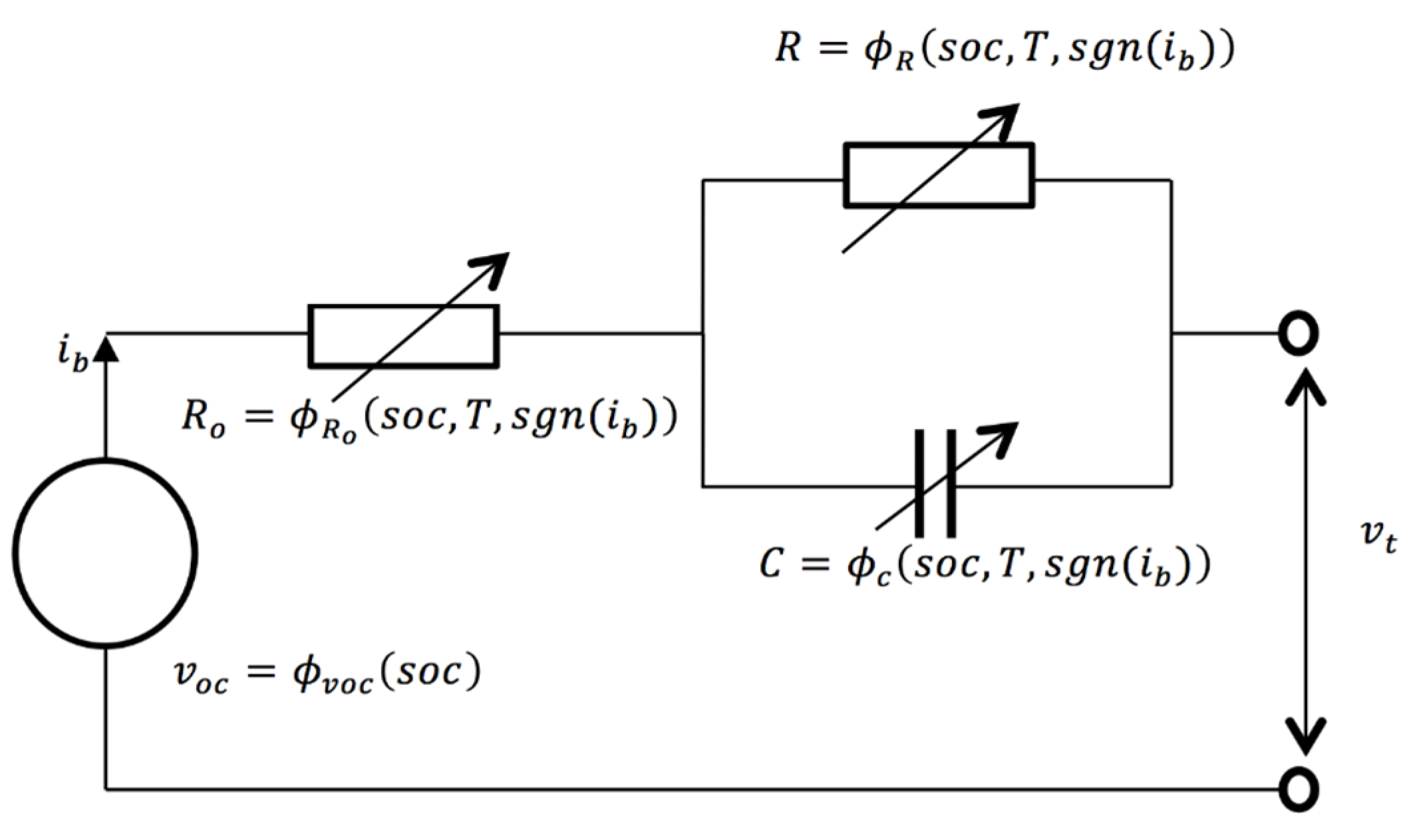
3.1. Model Structure

The creation of models to support the design and evaluation of Li-ion batteries has been the subject of considerable research [23,28,29,30,31]. Mathematical models vary widely in complexity, computational requirements and reliability of prediction. Models based on electrochemical principles attempt to include first-principle phenomena (e.g., intercalation, diffusion and species concentration) to improve model fidelity in an attempt to maintain the causal link between simulation results and observable phenomena [32]. Such simulations are known to require significant computational resources for model execution and detailed datasets for parameterisation [33]. The development of high-fidelity single-cell models is of immense value to the scientific community investigating novel cell designs and innovations in material science. However, due to their structural complexity and computational burden, they are arguably of less value for system-level analysis. The need to accurately and efficiently model cell behaviour within the context of a multi-cell environment is a strategic requirement for ESS engineers. A number of recent publications advocate the use of ECMs as the most appropriate trade-off between electrochemical models and, at the other end of the spectrum, simply modelling the battery as an empirical function [16,25,31,34,35]. Their relatively simple structure facilitates fast computation, while still providing some insights into the causality within the battery and hence the ability to correlate the simulation output with measureable parameters such as open circuit voltage (OCV) and steady-state resistance. Reference [36] compares 12 possible choices for an ECM and concludes that a first order ECM is sufficient to model the battery dynamics. As such, a first order ECM is developed with the parameters being a function of SOC, temperature and current direction. This comparatively low-fidelity model maintains both the numerical stability and accuracy of the simulation when executed in real time. Figure 1 presents the ECM used to emulate the dynamics of the Li-ion cell described in Section 2.
Figure 1. Real-time equivalent circuit model (ECM) structure.
Energies 08 08244 g001
The dominant mass-transfer dynamics of the cell can be represented using the first-order differential and algebraic equations below:
v ˙ c = 1 C ( i b v c R )
v t = v oc i b R o v c
where:
v oc = ϕ v oc ( soc )
C = ϕ c ( soc , T , sgn ( i b ) )
R = ϕ R ( s o c ,   T , sgn ( i b ) )
R o = ϕ R o ( T )
The R-C branch represents the mass diffusion dynamics within the cell, Ro the internal DC resistance and voc the open circuit voltage. As shown in Figure 2 and discussed in Section 3.2 each parameter is a non-linear function ( ϕ ) of cell temperature and in the case of R-C, cell SOC as well.

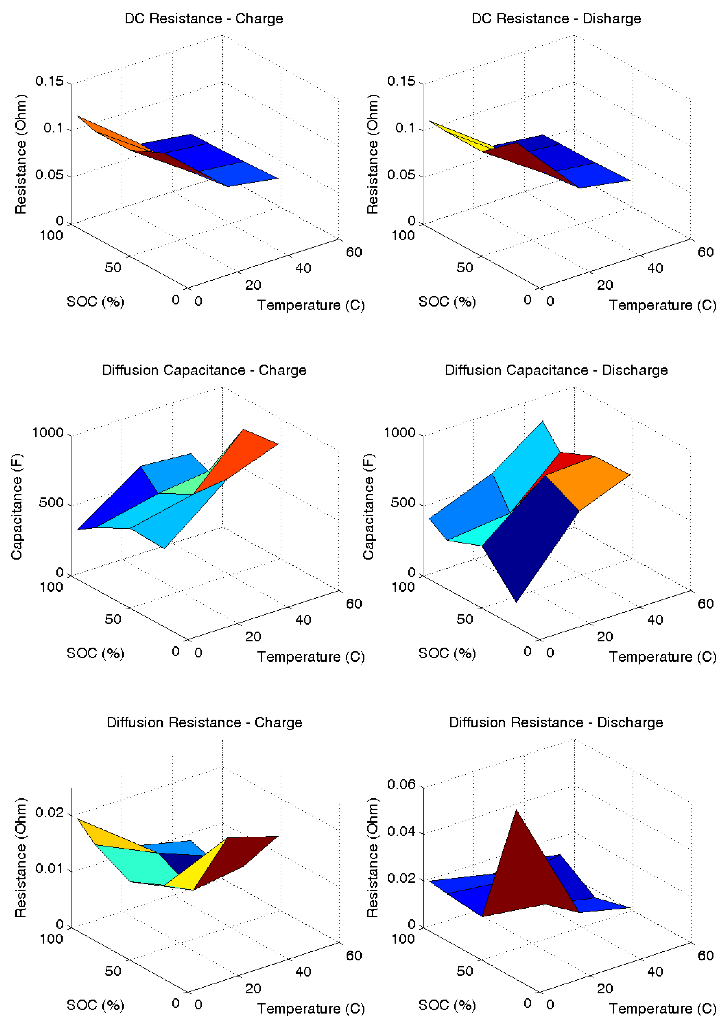
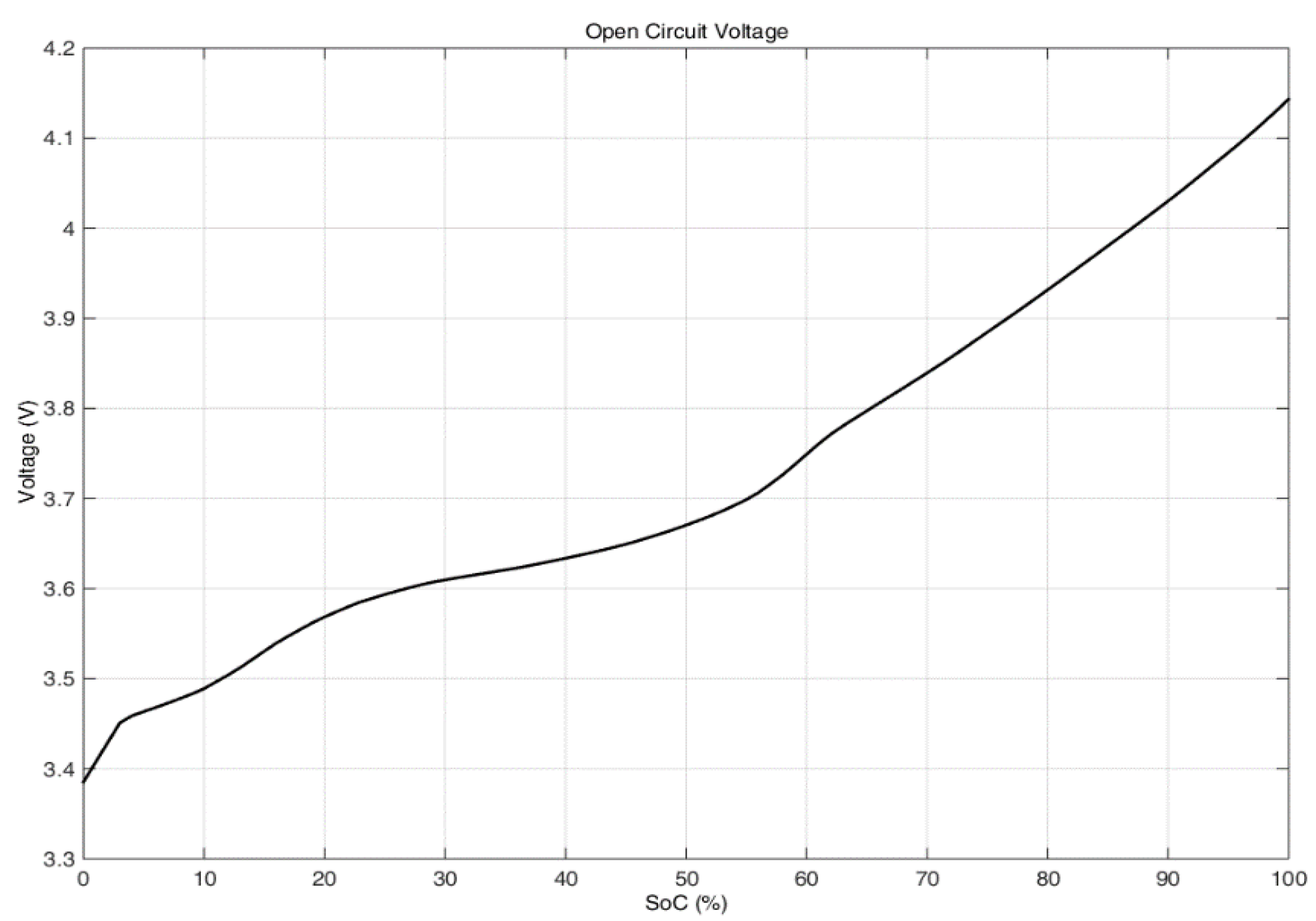
3.2. Parameter Estimation

The parameters of the cell model were estimated from data obtained through HPPC in line with the IEC 62660-1 Standard. The HPPC test consists of a series of 10 s discharge and charge pulses of increasing C-rate alternatingly applied at a pre-defined SOC. A rest-interval of 30 min is allowed between each pulse for the voltage dynamics of the cell to settle. By applying the current pulse set at different SOCs and repeated at different temperatures, the cell can be parameterised as a function of SOC and temperature. For the Samsung 18650 cell, SOC and temperature set points included SOC at 20%, 50%, 80% and 95% and ambient temperatures of 0 °C, 25 °C and 45 °C. From Figure 1, a differential algebraic equation (DAE) can be defined that relates each of the measured voltage responses to an applied current pulse:
v t = v oc R 0 · i b R · i b 1 C ocv i b · d t
d i b 1 d t = i b i b 1 τ
Figure 2. ECM parameter values.
Energies 08 08244 g002
Equation (7) is obtained by Kirchoff’s voltage law where the voltage across the ECM components in series are summed together, and the ODE in Equation (8) is obtained by applying Kirchoff’s current law on the RC parallel network. Note that in Equation (7) an additional voltage component, the product of Cocv and the integral of ib, is included which is not present in the ECM model of Figure 1. This is in line with similar studies, where an additional capacitive term (Cocv) has been added to account for the small OCV change due to the change in the cell’s SOC from the applied HPPC pulse. The parameter Cocv is only of significance when estimating the model parameters. During model simulation, however, Cocv is set to zero since the OCV that is characterized separately, is interpolated via a look-up table as a function of SOC and replaces the function of the capacitor term Cocv.
The current ib1 in Equation (8) defines the branch current within the resistive portion of the RC parallel network and τ is the time-constant of the mass-transfer dynamics. To estimate the parameters (Ro, R, τ, Cocv) of Equations (7) and (8), the equations need to be evaluated for a given current and time interval. Equation (8) being a first order linear ODE is easily solved numerically over a discrete set of time points. By assuming a zero initial condition for Equation (8) and that ib1 is constant between sampling intervals Equation (8) is solved for ib1 by the exponential integrator discretisation method [37] and is substituted into Equation (7) to obtain vt.
To estimate the parameters of Equations (7) and (8) a quadratic cost-function (F) and constraint are defined:
Minimise   F ( θ ) =   1 2 t = 0 t max [ v t e v t ( θ ) ] 2  
( subject to   θ i 0 )
Where vte defines the measured terminal voltage in response to a HPPC pulse measured over a time period of tmax (tmax = 1810 s), vt(θ) the modelled terminal voltage calculated from Equation (7) and θ is a parameter vector; in that θ = [Ro, R, τ, Cocv] with each parameter (θi) constrained to be non-negative (Equation (9)). The voltage (vt) is non-linear with respect to the time-constant (τ). Because of this non-linearity, an iterative non-linear optimisation, namely the trust-region reflective (TRR) algorithm is used. To initiate the optimisation, the algorithm requires an initial estimate of the parameters and the Jacobian matrix (Jθ) of Equation (7). The initial parameter estimates θ ^ were populated using the measured current and voltage traces derived from the HPPC data. Both Jθ and θ ^ were passed as arguments to the TRR optimisation routine that is commercially available within the Mathworks Optimisation Toolbox. Figure 2 presents the results of the parameterisation process, in which the optimal values for the ECM components are presented as a function of both SOC and temperature.
The OCV–SOC relationship presented in Figure 3 was derived experimentally based on three cells using a procedure based on IEC 62660-1. The cell was placed within a thermal chamber and allowed to stabilise at 25 °C for 12 h. To generate the discharge curve, the cell was fully charged using the manufacturer’s recommended constant current–constant voltage (CC–CV) procedure. The cell was then discharged at 1 C for 108 s (3% of capacity).
Figure 3. Average open circuit voltage-state of charge (OCV-SOC) relationship.
Energies 08 08244 g003
The cell was allowed to stabilise for 4 h before a voltage measurement was made. This incremental discharge procedure was repeated until the cell reached 1% SOC. For the corresponding charge curve, the cell was charged, again at a rate of 1 C in steps of 3% until the cell was fully charged. After each 108 s charge pulse the cell was allowed to rest for 4 h before a voltage measurement was made. The discharge and charge OCV curves are then averaged to obtain a single OCV-SOC curve and further averaged over the three cells (Figure 3).

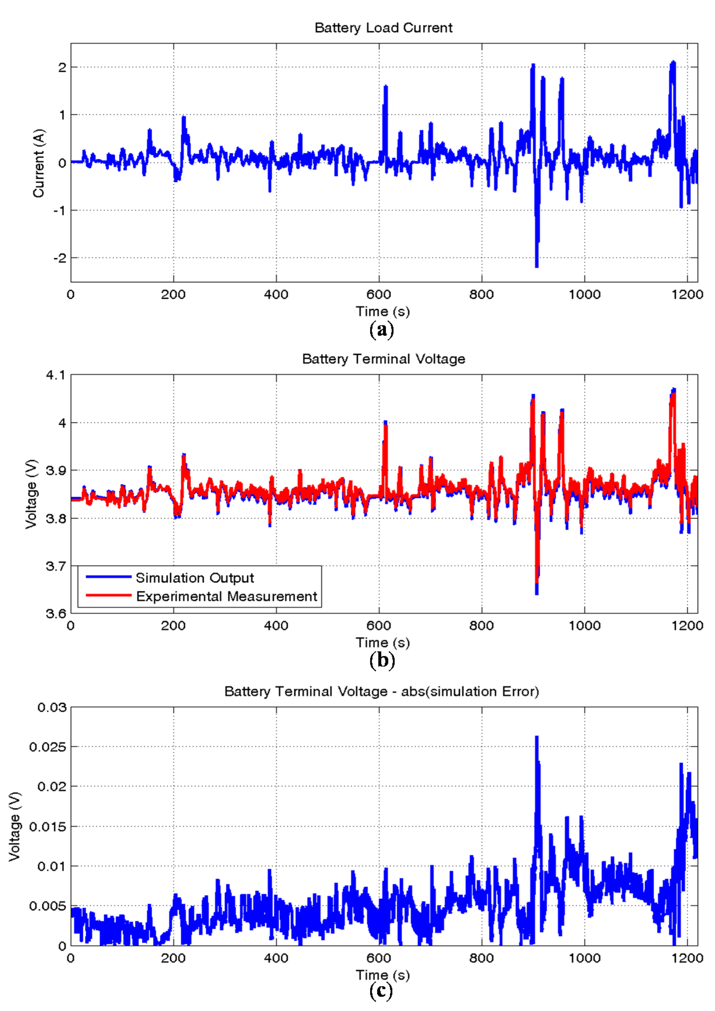
3.3. Off-Line Simulation and Model Validation

Validation of the cell model defined by Equations (1)–(6), within the time-domain is presented in Figure 4. The figure presents the correlation of the predicted terminal voltage (vt) with an experimental measurement (vte) of terminal voltage when the cell is subject to a transient current profile (ib). The current was recorded from a prototype electric vehicle (EV) when the vehicle was operating within an urban environment and subject to frequent acceleration (positive current) and regenerative braking (negative current) demands.
Figure 4. Validation of the ECM for off-line simulation: (a) battery load current; (b) terminal voltage; (c) simulation error.
Energies 08 08244 g004
The current profile was scaled to a peak value corresponding to the maximum charge C-rating (1 C, 2.2 Amps) of the cell. Figure 4 also presents the absolute of the error, defined by (|vtvte|), in which the average difference between the simulated and experimental results are in the order of 5 mV with a peak difference of approximately 25 mV.

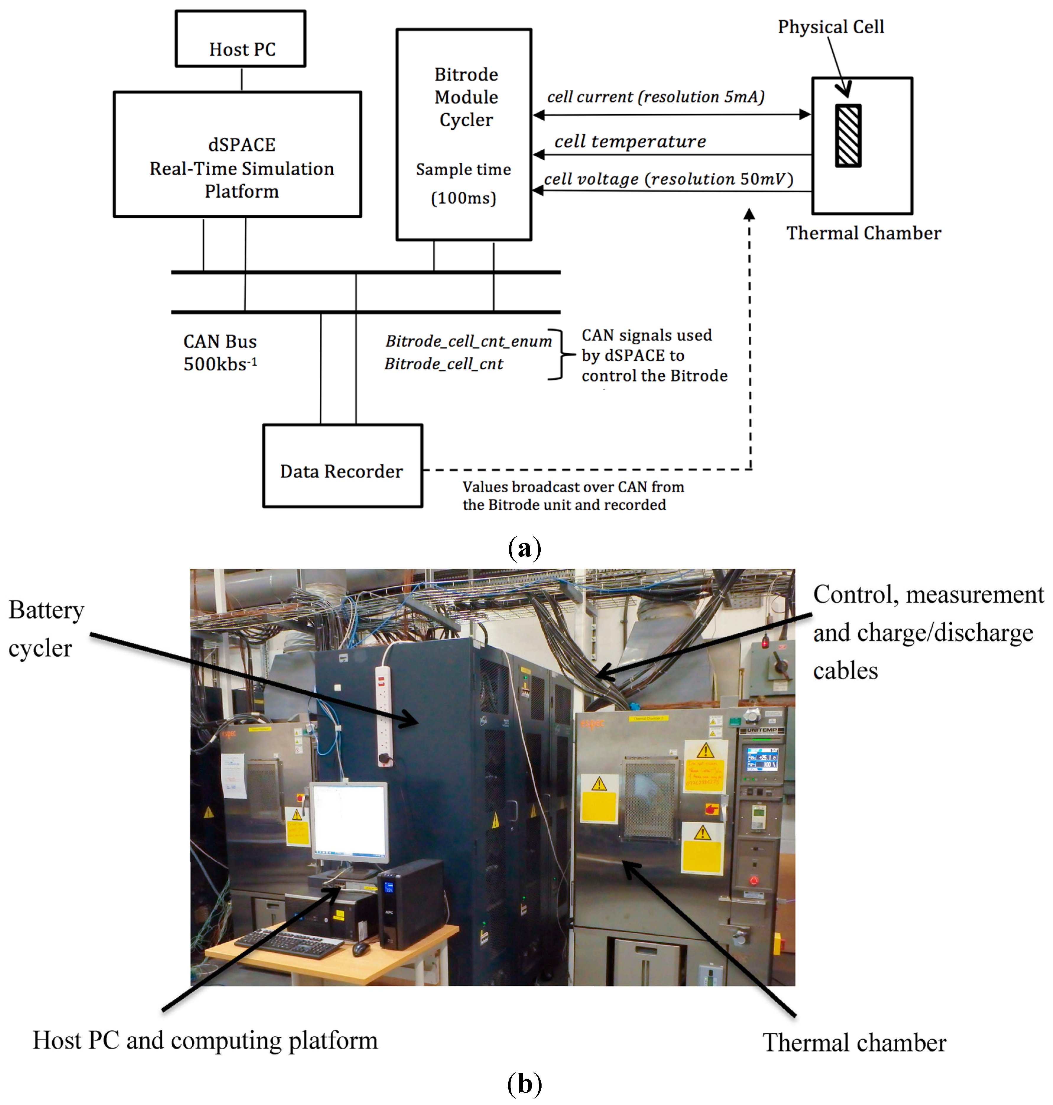
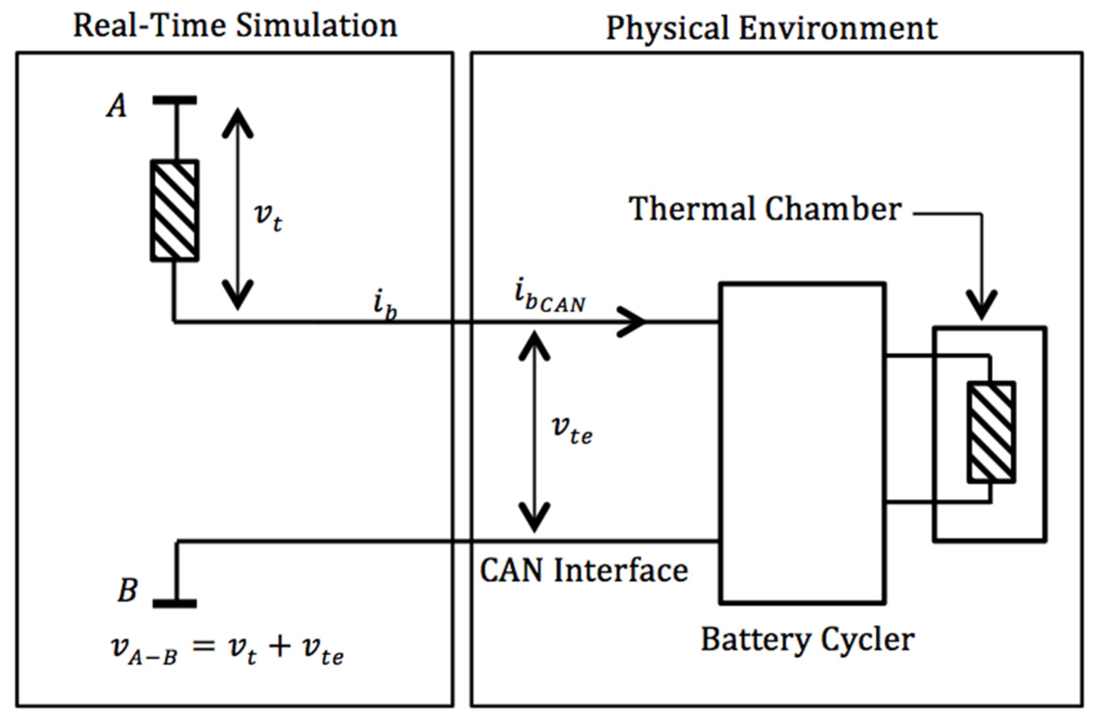
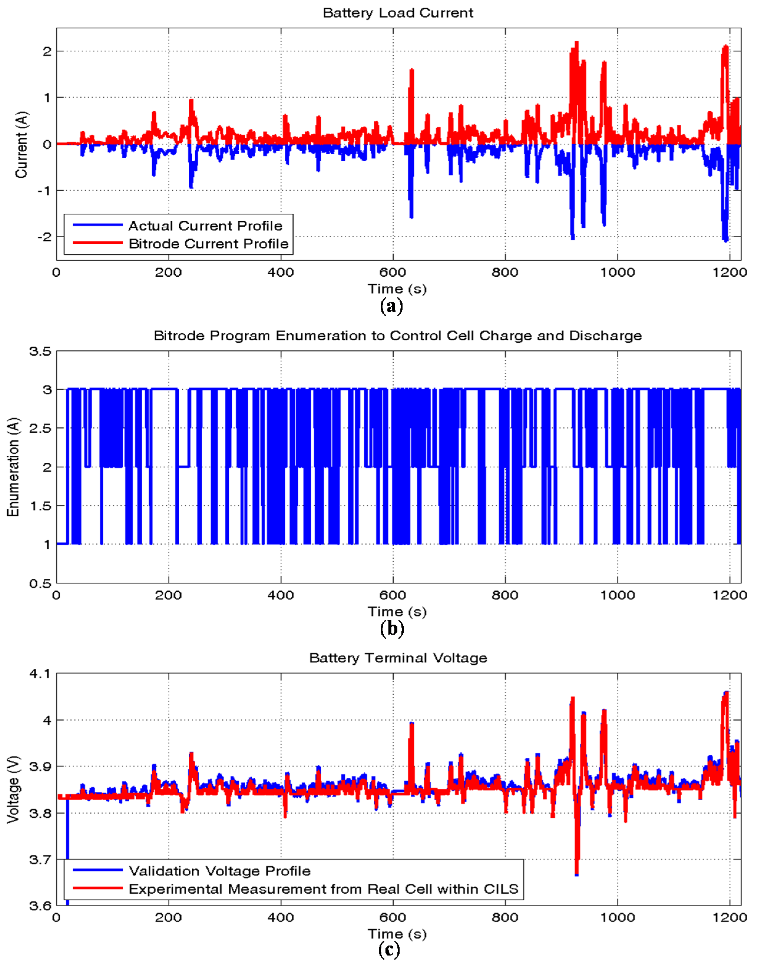
4. Hardware-in-the-Loop Simulation Environment and Real-Time Validation

Figure 5 presents a schematic representation of the CILS environment and the laboratory set-up employed to conduct the real-time simulation tests. The experimental set-up comprises a host PC, a real-time simulator (dSPACE, Paderborn, Germany), a battery module cycler (Bitrode, St. Louis, MO, USA) and a thermal chamber (Espec, Hudsonville, MI, USA). Communication between the battery cycler and real-time simulation environment was achieved using a Controller Area Network (CAN) bus, with a data transmission rate of 500 kbs.
Figure 5. (a) Schematic of the experimental set-up for cell-in-the-loop simulation (CILS); (b) laboratory set-up for CILS.
Energies 08 08244 g005
In order to estimate the reduction in accuracy when executed in real-time, the model was linearized to produce an incremental transfer-function between cell current and cell terminal voltage. The operating point was defined as: SOC = 50% and T = 25 °C. The poles of the characteristic equation highlight a natural frequency (ω) in the order 0.15 rads−1 and cell dynamics that are critically damped. The reduction in system phase margin (φ) by executing the model in real-time was calculated using Equation (11) and found to be 2° (from 90° to approximately 88°) with a simulation step-time (Ts) of 10 ms. As discussed within [38], this reduction would not negatively impact either the accuracy of the simulation or the numerical stability of the solution:
φ = ω T s
A simulation test was defined to validate the CILS approach and the cell model when operating in real-time. The test consists of two cells connected electrically in series, in which one is the physical cell exercised through the Bitrode battery cycler and the other is a simulation model running on the real-time simulation platform. Figure 6 presents the structure of the validation test. Within the host PC, the model was constructed using the Mathworks toolset, Simulink and Matlab and converted to a real-time software program using the proprietary Real-Time Workshop and dSPACE Target Language Compiler (TLC). From the host PC it was possible to download and control the simulation.
Figure 6. Experimental set-up for validation of the CILS environment.
Energies 08 08244 g006
A first-order, fixed-step Euler numerical integration algorithm was employed to solve the model equations. The current profile (ib) was also loaded onto the real-time simulator. As can be seen from Figure 4, the real-world profile comprises positive and negative current transients. For compatibility with the battery cycler’s control program the absolute value of ib was calculated:
i b CAN = abs ( i b )
A separate enumeration (birtode_cell_cnt_enum) was created to define the status of the battery cycler and the loading on the 18650 cell. Values of 1, 2 or 3 were employed to define if the cell was at rest, being discharged or being charged respectively. The term ( i b CAN ) defines the current value broadcast over CAN from the dSPACE simulator to the battery cycler. For CAN transmission, i b CAN was packed into an unsigned 16-bit word with a resolution of 0.07 mA/bit and transmitted at a sample rate of 10 ms (equal to the execution rate of the real-time model).
The test program consists of three main sections; battery at no-load, battery under charge and finally, battery under discharge. Transitions between the three parts of the test program are controlled in real-time by the enumeration birtode_cell_cnt_enum. Safety limits that result in the electrical isolation of the cell (for under voltage and over voltage conditions) were also coded within the program to ensure the safe operation of the test. To ensure deterministic ambient conditions throughout the test, the physical cell was located within the thermal chamber, with a temperature (T) set to 10 °C. From the manufacturer’s literature, the resolution of the output current channel from the cycler is defined as 5 mA. Throughout the test, the terminal voltage of the physical cell was recorded at a sample rate of 100 ms (the maximum rate within the cycler) and at an accuracy of 50 mV/bit using the on-board 10-bit analogue-to-digital converter (ADC). To facilitate data logging, this value was broadcast over CAN as an unsigned 32-bit word.
Figure 7 presents the results of the HILS validation test. The figure shows the transient current profile (ib) used to verify the off-line model.
Figure 7. Validation of the ECM and CILS environment for real-time testing: (a) battery load current; (b) current control signal; (c) battery terminal voltage.
Energies 08 08244 g007
The version of battery current converted for transmission over CAN to control the electrical load on the physical cell is also presented. In addition, the terminal voltage from both the simulated cell executed in real-time on the dSPACE platform and the measured terminal voltage of the physical cell broadcast over CAN by the battery cycler are shown. Since the simulation was set-up to emulate both cells connected in series and the cell model was parameterised to correlate with the pre-conditioned state of the physical cell (i.e., SOC = 70% and T = 10 °C), the resulting terminal voltages are almost identical. The absolute error between the measured cell voltage and the simulated cell voltage is comparable to that observed during off-line validation of the model. Minor differences between the off-line and CILS results can be accounted for by the quantisation of the voltage measurements through the ADC and data type conversion for broadcasting over the CAN.

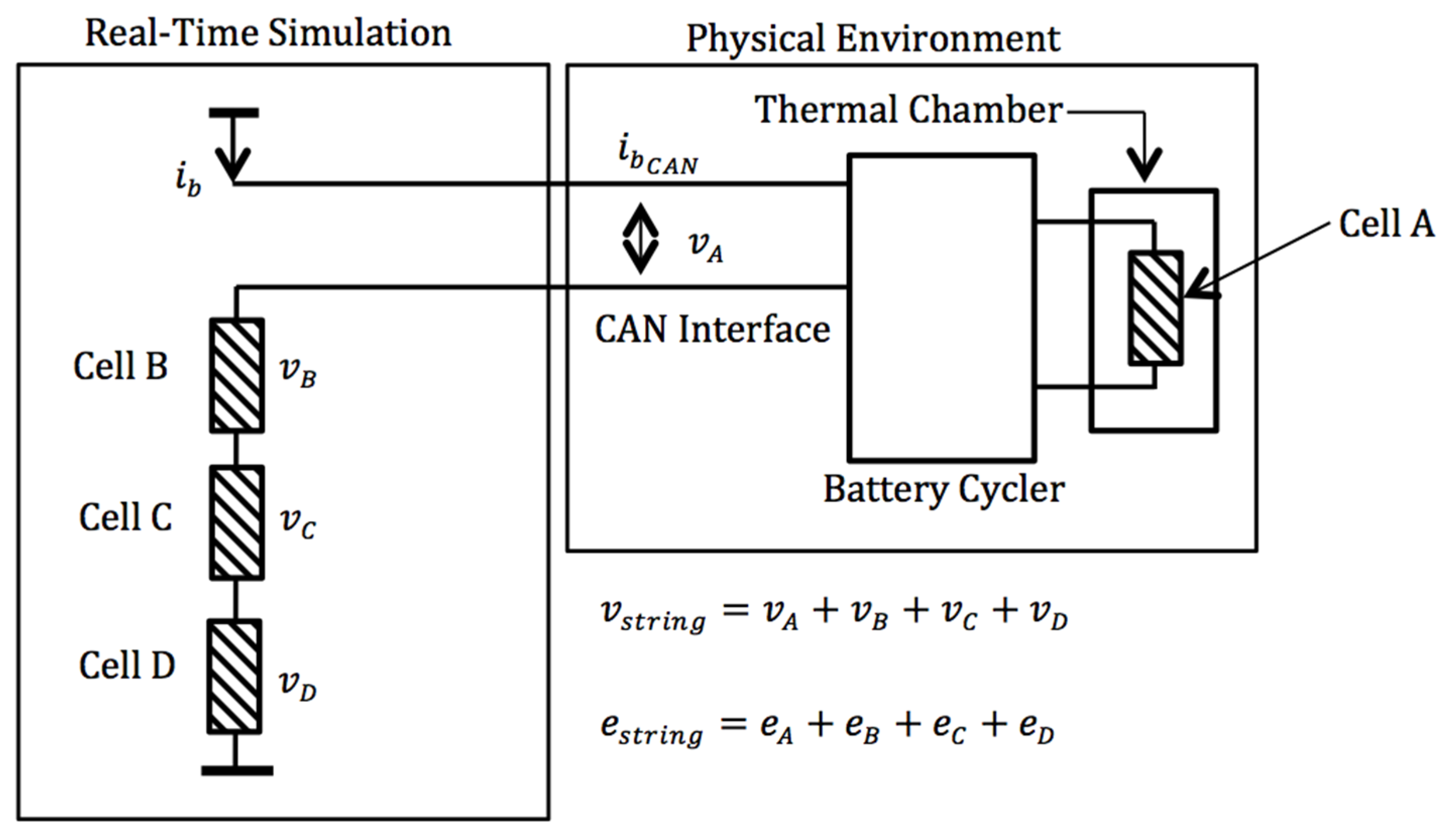
5. Case Study: Defining the State of Charge (SOC) for a Series Connection of 18650 Cells

The need to quantify to the stored energy within a Li-ion cell underpins many of the safety and energy management functions within a BMS control system [26,37]. Properly defining and estimating SOC for Li-ion cells has therefore been the subject of considerable academic and industrial research and includes studies that employ relatively simple coulomb counting and voltage relaxation methods [35], through to more computationally demanding state estimation methods [39,40,41], typically based on the generic structure of a Kalman Filter [42,43], or observer [32,44]. A recent publication [45] attempts to revaluate the definition of SOC specifically within the context of different voltage relaxation times required for the cell to stabilise (including the practical limitations of this) and improved methods of calculating SOC within a multi-cell system. Using a 3s1p topology (i.e., 3 cells within a single string), the paper highlights the errors that may occur when estimating system SOC by simply scaling the assumed SOC of individual cells. This is particularly evident when significant component variability or energy imbalance exists within the ESS. Off-line simulation is employed to illustrate the magnitude of the discrepancy.
Figure 8 presents the CILS set-up for this case study, in which four cells (cell A, cell B, cell C and cell D) are connected electrically in series (4s1p).
Figure 8. Experimental set-up for the case-study—CILS of four cells in series.
Energies 08 08244 g008
Significant component variability exists within the string. Cell A is defined as the nominal cell with a capacity and impedance represented by the characterisation data presented in Section 3.2. Conversely, cell B has a 10% increase in internal impedance, cell C a 10% reduction in energy capacity and finally cell D a reduced capacity of 10% and an increase in impedance by 10%.
From the cell specification for the 18650 cell, it is noteworthy that to experimentally degrade the cell to achieve a 10% capacity fade would require approximately 200 cycles at a 1 C charge/discharge rate, requiring approximately 20 days, assuming 10 cycles per 24 h could be maintained within the test facility. Further details on the expected variability of cells integrated within a complete ESS is discussed further within [6].
As it can be seen from Figure 8, the nominal cell (cell A) constitutes the physical cell within the CILS test, whereas cells B, C and D are represented by three instantiations of the real-time simulation model introduced in Section 3. The component degradation for cells B, C and D represent the combined effects of manufacturing tolerances and the differential effects of ageing and were implemented within the model via a reduction in cell capacity and an increase in cell impedance. For this test, cell A was placed within the thermal chamber (T = 25 °C) and allowed to stabilise for 12 h. The cell was then charged using the manufacturer’s recommended charging process (CC-CV) to the upper voltage threshold. Each of the virtual cells (B, C and D) were initialised with a SOC = 100%. A constant 1 C discharge current was applied to the series string. The simulated value of i b was converted to i b C A N and broadcast over CAN to the battery cycler, thereby electrically loading the physical cell in real-time and in exactly the same way as that employed within the simulation. The discharge current was automatically set to zero by the real-time simulator when any of the four cell voltages dropped below the lower threshold.
Figure 9 presents the results from this case study. The figure shows the discharge voltage curves for cells (A, B, C and D). The figure also presents the off-line simulated voltage for cell A and that measured during the CILS test and broadcast over CAN. As expected, the rate of voltage decrease for cell D is greatest and it is the first voltage to drop below the lower threshold. Using both a direct measure of capacity throughput from the Bitrode battery cycler and an indirect calculation based on experimentation time, the results show that 1.07 Ah was extracted from the 4s1p string before the cut of voltage was reached.
Figure 9. Terminal voltage of each cell under a 1 C constant current discharge.
Energies 08 08244 g009
This is only 55% of the 1.92 Ah theoretically available if the new cell (cell A) was integrated within a 4s1p string comprising of cells of equal quality. Of particular interest for this study is the high degree of correlation that exists between the measured and simulated results that once again reaffirm the CILS approach for emulating the real-world integration challenge.

6. Discussion

The traditional method of evaluating cell performance is through the use of standards such as IEC 62660-1 [21] that define generic open-loop test sequences for HPPC and energy capacity. Such tests are analogous to legislative vehicle drive-cycles employed within the international automotive industry. For example, the New European Drive Cycle (NEDC) is a legislative test profile that vehicle manufacturer’s most report against for fuel economy and exhaust emissions. The standard is widely reported within the literature not to represent real-world vehicle usage. Within the context of ESS, the CILS approach facilitates the creation of closed loop test cases in which derivation of the load profile can be predefined or created in real-time, i.e., through the inclusion within the simulator of a model of an EV powertrain or wind-turbine. Further, the condition of the cell (fed back in real-time) can be employed to influence the load profile. As discussed within [19,20,22], given that cell cycle ageing and performance degradation are inherently linked to its usage profile, there are obvious benefits in being able to emulate the real cell environment early within the ESS design life-cycle. The aim of this section is to discuss further the applicability of this CILS approach and the main areas for future research.

6.1. Application

The methodology for CILS evaluation presented here will be of significant benefit to a broad spectrum of researchers, including those that work on the interfaces of energy storage science, engineering and manufacturing. Scientists face a significant challenge when scaling up individual cell prototypes to a complete integrated system with an energy density, power density, degradation rate, weight and cost that is commensurate with end-user requirements. CILS may be employed to support the transition from laboratory research through to industrial application. Using CILS, it is feasible to obtain performance data from a single prototype cell as if it were operating within a complete ESS. One avenue for further research would be the possibility to trade-off performance metrics for the ESS with manufacturing targets and tolerance for individual cells. The design and early-stage verification of key BMS functions such as SOC, SOH, battery diagnostics and prognostics represent a unique challenge [26]. Designs are often based on simplified single cell models that inherently assume homogeneity and ignore further components of the system. CILS may feasibly allow the concurrent design and manufacture of the physical ESS with the controller design—expanding the creative space for new innovative algorithms. ESS researchers working at technology readiness levels (TRL) 5–9 are often required to evaluate system designs for improved energy/resource efficiency within the context of their final application (i.e., transport, the built environment or grid-scale storage). However, at the initial stages of development they will often be hampered by a lack of component availability. Furthermore, the commercial, engineering and safety implications associated with physical testing and design of the complete ESS will often be prohibitive. Within a safe, cost effective, and deterministic environment, CILS may be employed to support a fundamental understanding of the impact of duty-cycles, manufacturing uncertainties, cell-to-cell interactions and thermal variations on system performance, reliability and degradation.

6.2. Further Work

This research has presented the concept and verified the operation of a CILS test environment. The scope of this initial study was constrained to the integration of a physical cell with a real-time battery model and exercised against a realistic electrical load. The case study reviewed the series interconnection of cells and demonstrated how the energy available from a new cell when integrated within a set of degraded cells may be considerably lower. Given that most commercial vehicle battery systems employ a topology using cells in both series and parallel, a further application of CILS would investigate a parallel connection of differentially aged cells. For cells having different values of impedance and capacity, initial research has already highlighted the differential current flow that is possible between adjacent current paths and the resulting impact that this has on system efficiency, ageing and safety [46]. In order to meet the potential end-user requirements introduced in Section 6.1, two primary challenges remain and are the subject of on-going research by the authors. In addition to electrochemical cells, a complete ESS may comprise control and monitoring electronics, safety devices, ancillaries for heating/cooling and both high voltage and low voltage cabling. The inclusion of real-time models for the balance-of-plant will improve the fidelity of the complete system model. Research into real-time electrical fuse modelling has already been presented [47]. With an emphasis on real-time simulation, research is on-going to develop the required model library that optimises the trade-off between the “cost” (effort, computational burden and parameterisation requirements) with the “benefit” of maintaining the causal relationships of the physical subsystems within the model structure. As discussed within Section 2, one of the primary causes for differential cell ageing within the ESS is the presence of thermal gradients within the pack. This conclusion has been confirmed by recent publications, including [1,3]. The CILS environment must therefore be able to emulate such thermal variations and, through real-time control of the physical cell’s ambient temperature, be able to emulate that cell’s respective eco-system within the ESS. The research challenge is considerable and requires the real-time calculation of both heat generation within the cell under test (due to thermodynamic and ohmic processes) and the heat transfer from adjacent cells taking into account conduction efficiencies, cooling and heating circuits. Research is currently on-going by the authors to create and parameterise the models required, in addition to the evaluation of the thermal environment required to house the physical cell under test that has the ability to dynamically vary the ambient temperature of the cell in line with the requirements of the real-time simulation model.

7. Conclusions

This paper presents the first stage of the validation process for a CILS concept in which a real-time simulation model of an 18650 Li-ion cell has been electrically connected to a physical cell and exercised over a real-world demand profile. Within this study, CILS is presented within the context of an enabling technology to undertake an efficient test programme that aims to investigate the impact of differential ageing and electrical loading within the ESS. A case study is presented that demonstrates how the energy available from a new cell when integrated within a set of degraded cells may be considerably less than that assumed from the characterisation of the new cell in isolation. While this may be in line with expected results, the case study shows the applicability of this approach, namely the drawing together of both physical testing and real-time simulation such that the characterisation of a single cell can be done within the context of the complete ESS environment and real-world usage demands. The CILS approach has been validated using real-world data recorded from an EV operating within an urban environment. Experiments show a high degree of correlation between results obtained through off-line simulation and direct voltage measurements made of the cell being tested. On-going research has been discussed that aims to extend the CILS approach to include a thermal characterisation of the ESS that can be executed in real-time with the existing electrical system models. The derivation, integration and verification of the electrical-thermal ESS real-time simulation and CILS test environment will be the subject of further publications.

Acknowledgments

This research was supported by the University of Warwick Research Development Fund in collaboration with the Innovate UK funded WMG Centre High Value Manufacturing (HVM) Catapult.

Author Contributions

All authors contributed to this research. James Marco was the Principal Investigator and lead author. Peter Jones was the research Co-Investigator and contributed to the Hardware-in-the-loop simulation. Neelu Kumari undertook the experimentation and Dr Widanage completed the optimisation and model parameterisation activity.

Conflicts of Interest

The authors declare no conflict of interest.

References

  1. Wu, B.; Yufit, V.; Marinescu, M.; Offer, G.J.; Martinez-Botas, R.F.; Brandon, N.P. Coupled thermal–electrochemical modelling of uneven heat generation in lithium-ion battery packs. J. Power Sources 2013, 243, 544–554. [Google Scholar] [CrossRef]
  2. Thanheiser, A.; Kohler, T.P.; Bertram, C.; Herzog, H.G. Battery emulation considering thermal behavior. In Proceedings of the 2011 IEEE Vehicle Power and Propulsion Conference, Chicargo, IL, USA, 6–9 September 2011; pp. 1–5.
  3. Marinescu, M.; Wu, B.; von Srbik, M.; Yufit, V.; Offer, G.J. The effect of thermal gradients on the performance of battery packs in automotive applications. In Proceedings of the IET Hybrid Electric Vehicle Conference (HEVC), London, UK, 6–7 November 2013.
  4. Gogoana, R.; Pinson, M.B.; Bazant, M.Z.; Sarma, S.E. Internal resistance matching for parallel-connected lithium-ion cells and impacts on battery pack cycle life. J. Power Sources 2014, 252, 8–13. [Google Scholar] [CrossRef]
  5. Wu, J.; Member, S.; Wang, J.; Li, K. Large-scale energy storage system design and optimization for emerging electric-drive vehicles. IEEE Trans. Comput. Aided Des. Integr. Cicuits Syst. 2013, 32, 325–338. [Google Scholar] [CrossRef]
  6. Dubarry, M.; Vuillaume, N.; Liaw, B.Y. From single cell model to battery pack simulation for Li-ion batteries. J. Power Sources 2009, 186, 500–507. [Google Scholar] [CrossRef]
  7. Kenney, B.; Darcovich, K.; MacNeil, D.D.; Davidson, I.J. Modelling the impact of variations in electrode manufacturing on lithium-ion battery modules. J. Power Sources 2012, 213, 391–401. [Google Scholar] [CrossRef]
  8. Santhanagopalan, S.; White, R.E. Quantifying cell-to-cell variations in lithium ion batteries. Int. J. Electrochem. 2012, 2012, 1–10. [Google Scholar] [CrossRef]
  9. Lotfi, N.; Fajri, P.; Novosad, S.; Savage, J.; Landers, R.; Ferdowsi, M. Development of an experimental testbed for research in lithium-ion battery management systems. Energies 2013, 6, 5231–5258. [Google Scholar] [CrossRef]
  10. Molitor, C.; Member, S.; Benigni, A.; Helmedag, A.; Chen, K.; Calì, D.; Jahangiri, P.; Müller, D.; Monti, A.; Member, S. Multiphysics test bed for renewable energy systems in smart homes. IEEE Trans. Ind. Electron. 2013, 60, 1235–1248. [Google Scholar] [CrossRef]
  11. Guo, F.; Member, S.; Inoa, E.; Choi, W.; Wang, J. Study on global optimization and control strategy development for a PHEV charging facility. IEEE Trans. Veh. Technol. 2012, 61, 2431–2441. [Google Scholar] [CrossRef]
  12. Allen, J. Simulation and test systems for validation of electric drive and battery management systems. SAE Tech. Paper 2012. [Google Scholar] [CrossRef]
  13. Bazargan, D.; Filizadeh, S.; Bistyak, G. Battery Characterization for Vehicular Applications using hardware-in-loop real-time simulation. In Proceedings of the 23rd International Conference on Electric Power and Energy Conversion Systems, Instabul, Turkey, 2–4 October 2013; pp. 1–6.
  14. Xiong, R.; He, H.; Sun, F.; Zhao, K. Online estimation of peak power capability of Li-ion batteries in electric vehicles by a hardware-in-loop approach. Energies 2012, 5, 1455–1469. [Google Scholar] [CrossRef]
  15. He, Y.; Liu, W.; Koch, B.J. Battery algorithm verification and development using hardware-in-the-loop testing. J. Power Sources 2010, 195, 2969–2974. [Google Scholar] [CrossRef]
  16. He, Y.; Liu, W.; Koch, B.J. Power capability testing of a lithium-ion battery using hardware in the loop. SAE Tech. Paper 2010. [Google Scholar] [CrossRef]
  17. He, H.; Xiong, R.; Zhao, K.; Liu, Z. Energy management strategy research on a hybrid power system by hardware-in-loop experiments. Appl. Energy 2013, 112, 1311–1317. [Google Scholar] [CrossRef]
  18. Dai, H.; Zhang, X.; Wei, X.; Sun, Z.; Wang, J.; Hu, F. Cell-BMS validation with a hardware-in-the-loop simulation of lithium-ion battery cells for electric vehicles. Int. J. Electr. Power Energy Syst. 2013, 52, 174–184. [Google Scholar] [CrossRef]
  19. Stroe, D.I.; Swierczynski, M.; Stan, A.I.; Teodorescu, R. Accelerated lifetime testing methodology for lifetime estimation of Lithium-ion batteries used in augmented wind power plants. IEEE Trans. Ind. Appl. 2014, 50, 4006–4017. [Google Scholar] [CrossRef]
  20. Omar, N.; Monem, M.A.; Firouz, Y.; Salminen, J.; Smekens, J.; Hegazy, O.; Gaulous, H.; Mulder, G.; Van den Bossche, P.; Coosemans, T.; et al. Lithium iron phosphate based battery—Assessment of the aging parameters and development of cycle life model. Appl. Energy 2014, 113, 1575–1585. [Google Scholar] [CrossRef]
  21. Omar, N.; Daowd, M.; Hegazy, O.; Mulder, G.; Timmermans, J.M.; Coosemans, T.; Van den Bossche, P.; Van Mierlo, J. Standardization work for BEV and HEV applications: Critical appraisal of recent traction battery documents. Energies 2012, 5, 138–156. [Google Scholar] [CrossRef]
  22. Fernández, I.J.; Calvillo, C.F.; Sánchez-Miralles, A.; Boal, J. Capacity fade and aging models for electric batteries and optimal charging strategy for electric vehicles. Energy 2013, 60, 35–43. [Google Scholar] [CrossRef]
  23. Bizeray, A.; Duncan, S.R.; Howey, D.A. Advanced battery management systems using fast electrochemical modelling. In Proceedings of the IET Hybrid Electric Vehicle Conference (HEVC), London, UK, 6–7 November 2013; pp. 1–6.
  24. Birkl, C.R.; Howey, D.A. Model identification and parameter estimation for LiFePO4. In Proceedings of the IET Hybrid Electric Vehicle Conference 2013 (2013 HEVC), London, UK, 6–7 November 2013; pp. 1–6.
  25. He, H.; Xiong, R.; Fan, J. Evaluation of lithium-ion battery equivalent circuit models for state of charge estimation by an experimental approach. Energies 2011, 4, 582–598. [Google Scholar] [CrossRef]
  26. Waag, W.; Fleischer, C.; Sauer, D.U. Critical review of the methods for monitoring of lithium-ion batteries in electric and hybrid vehicles. J. Power Sources 2014, 258, 321–339. [Google Scholar] [CrossRef]
  27. Chaturvedi, N.A.; Christensen, J.; Ahmed, J. Modelling, Estimation and control challenges for lithium-ion batteries. In Proceedings of the 2010 American Control Conference (ACC), Baltimore, MD, USA, 30 June–2 July 2010; pp. 1997–2002.
  28. Hariharan, K.S. A coupled nonlinear equivalent circuit—Thermal model for lithium ion cells. J. Power Sources 2013, 227, 171–176. [Google Scholar] [CrossRef]
  29. Klein, R.; Chaturvedi, N.A.; Christensen, J.; Ahmed, J.; Findeisen, R.; Kojic, A. Electrochemical model based observer design for a lithium-ion battery. IEEE Trans. Control Syst. Technol. 2013, 21, 289–301. [Google Scholar] [CrossRef]
  30. Speltino, C.; Domenico, D.; Fiengo, G.; Stefanopoulou, A. Comparison of reduced order lithium-ion battery models for control applications. In Proceedings of the 48th IEEE Conference on Decision and Control, 2009 held jointly with the 2009 28th Chinese Control Conference, Shanghai, China, 15–18 December 2009; pp. 3276–3281.
  31. Lu, L.; Han, X.; Li, J.; Hua, J.; Ouyang, M. A review on the key issues for lithium-ion battery management in electric vehicles. J. Power Sources 2013, 226, 272–288. [Google Scholar] [CrossRef]
  32. Dey, S.; Ayalew, B.; Pisu, P. Nonlinear robust observers for state-of-charge estimation of lithium-ion cells based on a reduced electrochemical model. IEEE Trans. Control Syst. Technol. 2015. [Google Scholar] [CrossRef]
  33. Ramadesigan, V.; Northrop, P.W.C.; De, S.; Santhanagopalan, S.; Braatz, R.D.; Subramanian, V.R. Modeling and simulation of lithium-ion batteries from a systems engineering perspective. J. Electrochem. Soc. 2012, 159, 31–45. [Google Scholar] [CrossRef]
  34. Collet, A.; Crébier, J.; Chureau, A. Multi-cell battery emulator for advanced battery management system benchmarking. In Proceedings of the 2011 IEEE International Symposium on Industrial Electronics (ISIE), Gdansk, Poland, 27–30 June 2011; pp. 1093–1099.
  35. Antaloae, C.; Marco, J.; Assadian, F. A Novel method for the parameterization of a Li-ion cell model for EV/HEV control applications. IEEE Trans. Veh. Technol. 2012, 61, 3881–3892. [Google Scholar] [CrossRef]
  36. Hu, X.; Li, S.; Peng, H. A comparative study of equivalent circuit models for Li-ion batteries. J. Power Sources 2012, 198, 359–367. [Google Scholar] [CrossRef]
  37. Xing, Y.; Ma, E.W.M.; Tsui, K.L.; Pecht, M. Battery management systems in electric and hybrid vehicles. Energies 2011, 4, 1840–1857. [Google Scholar] [CrossRef]
  38. Marco, J.; Vaughan, N.D. The control-oriented design and simulation of a high voltage bus management strategy for use within hybrid electric vehicles. Int. J. Veh. Syst. Model. Test. 2007, 2, 345–368. [Google Scholar] [CrossRef]
  39. Plett, G.L. Extended Kalman filtering for battery management systems of LiPB-based HEV battery packs. Part 3: State and Parameter Estimation. J. Power Sources 2004, 134, 277–292. [Google Scholar] [CrossRef]
  40. Plett, G.L. Extended Kalman filtering for battery management systems of LiPB-based HEV battery packs. Part 2: Modelling and Identification. J. Power Sources 2004, 134, 262–276. [Google Scholar] [CrossRef]
  41. Plett, G.L. Extended Kalman filtering for battery management systems of LiPB-based HEV battery packs. Part 1: Backgrounds. J. Power Sources 2004, 134, 252–261. [Google Scholar] [CrossRef]
  42. Sepasi, S.; Ghorbani, R.; Liaw, B.Y. A novel on-board state-of-charge estimation method for aged Li-ion batteries based on model adaptive extended Kalman filter. J. Power Sources 2014, 245, 337–344. [Google Scholar] [CrossRef]
  43. Sepasi, S.; Ghorbani, R.; Liaw, B.Y. Improved extended Kalman filter for state of charge estimation of battery pack. J. Power Sources 2014, 255, 368–376. [Google Scholar] [CrossRef]
  44. Chen, X.; Shen, W.; Cao, Z.; Kapoor, A. A novel approach for state of charge estimation based on adaptive switching gain sliding mode observer in electric vehicles. J. Power Sources 2014, 246, 667–678. [Google Scholar] [CrossRef]
  45. Truchot, C.; Dubarry, M.; Liaw, B.Y. State-of-charge estimation and uncertainty for lithium-ion battery strings. Appl. Energy 2014, 119, 218–227. [Google Scholar] [CrossRef]
  46. Bruen, T.; Marco, J.; Gama, M. Current Variation in Parallelized Energy Storage Systems. In Proceedings of the 2014 IEEE Vehicle Power and Propulsion Conference, Coimbra, Portugal, 27–30 October 2014.
  47. Yang, C.P.; Ball, R.; Mcgordon, A.; Dhadyalla, G. Simulation methodologies to support novel fuse design for energy storage systems using COMSOL. In Proceedings of the IET Hybrid Electric Vehicle Conference 2013 (HEVC 2013), London, UK, 6–7 Novenmber 2013; pp. 1–5.

