Article

Inductive-Based Wireless Power Recharging System for an Innovative Endoscopic Capsule

The BioRobotics Institute, Scuola Superiore Sant’Anna, Viale R. Piaggio 34, Pontedera (Pisa) 56025, Italy
*
Author to whom correspondence should be addressed.
Energies 2015, 8(9), 10315-10334; https://doi.org/10.3390/en80910315
Submission received: 3 August 2015 / Revised: 12 September 2015 / Accepted: 14 September 2015 / Published: 21 September 2015
(This article belongs to the Special Issue Wireless Power Transfer)

Abstract

:
Wireless capsule endoscopic devices are adopted for painless diagnosis of cancer and other diseases affecting the gastrointestinal tract as an alternative to traditional endoscopy. Although much work has been done to improve capsule performance in terms of active navigation, a major drawback is the limited available energy on board the capsule, usually provided by a battery. Another key shortcoming of active capsules is their limitation in terms of active functionalities and related costs. An inductive-based wireless recharging system for the development of an innovative capsule for colonoscopy is proposed in this paper; the aim is to provide fast off-line battery recovery for improving capsule lifecycle and thus reducing the cost of a single endoscopic procedure. The wireless recharging system has been properly designed to fit the dimensions of a capsule for colonoscopy but it can be applied to any biomedical devices to increase the number of times it can be used after proper sterilization. The current system is able to provide about 1 W power and is able to recharge the battery capsule in 20 min which is a reasonable time considering capsule operation time (10–15 min).

1. Introduction

Wireless endoscopic capsules are extremely useful for early diagnosis of cancer and other diseases affecting the gastrointestinal tract, as an alternative to traditional endoscopy. The main advantage is that capsule endoscopy is typically well accepted by patients and, as demonstrated by studies, is painless [1,2]. However, commercially available pills are limited to screening and are purely passive devices that rely on peristalsis for the propulsion onto important medical target areas, such as the esophagus, stomach, small bowel and colon. In the last decade, many solutions have been explored to embed active locomotion mechanisms onto these devices and allow accurate and controlled navigation [3,4,5,6,7].
A major drawback of active capsules is their limitation in terms of active functionalities (e.g., possibility to carry out biopsies and provide therapies and surgeries such as polyps removal) that make endoscopic capsules more suitable for screening rather than outpatient procedures. In other cases, traditional colonoscopy is preferred for providing both endoscopy and surgery when needed within the same medical exam, thus reducing the related costs.
In the endoscopic capsule framework, in order to release a new generation of active endoscopic capsules able to effectively overcome the limits of traditional endoscopic procedures and definitively pave the way to a market for active endoscopic capsules, a way for reducing the procedural costs of painless endoscopic procedures must be found. An inductive-based wireless power recharging system for an innovative colonoscopic capsule is proposed in this paper. The wireless charging systems allows fast off-line battery recovery thus improving the capsule lifecycle of the endoscopic device and reducing the cost of a single endoscopic capsule procedure; in this way, the capsule is re-usable several times (up to 6–10 times) after proper sterilization. The endoscopic capsule in which the wireless recharging system has been integrated is based on an innovative spherical capsule designed to allow safe, accurate and effective locomotion along the colonic lumen after insertion into the rectum, in a completely wireless manner.
This paper wishes to introduce a general design principle for endoscopic capsules including a dedicated wireless recharging system so that the capsules may be reused after proper sterilization, as happens with traditional endoscopes. The designed wireless recharging system has been applied to a specific case study in order to demonstrate the value and feasibility of the approach. The proposed system is based on electromagnetic induction between two coaxial coils in a relative fixed position, typically exploited in commercial wireless chargers (Smart Phones, Portable Media Players, Digital Cameras, Tablets, Headsets, and medical device, e.g., cardiac pacemakers). To the best of the authors’ knowledge, this is the first time that a recharging system is integrated into an endoscopic capsule; the power source embedded into the capsule is charged by simply engaging it in a dedicated docking station.
An endoscopic device for the examination of the colon in fact represents an alternative or complementary method to current diagnostic techniques. Given its characteristics, colonoscopy has been taken as reference market since it is the most common clinical exam used to screen colorectal diseases. This market is continuously expanding and the number of patients examined annually has been constantly increasing for several years. This trend will most likely continue since numerous screening promotion campaigns have been launched. The cost of colonoscopy performed under general anesthesia is high and sometimes, since it is a painful procedure, needs to be performed in anesthesia. The use of endoscopic capsules having a similar performance as traditional endoscopes is not possible because of the cost that the customer would have to pay for the active capsules. The predicted cost to the final user would be about 480 € for the active capsule, while passive capsule systems would cost around 300 €. Both solutions need an external system (as in the case of traditional colonoscopes) with a cost of 10–15 k€. The wireless rechargeable system proposed in this paper for application in an active endoscopic capsule could make these costs drop drastically to under 80 € per procedure (considering that the capsule may be used a further six times).
Wireless powering solutions have been proposed by other research groups with the aim to continuously provide energy to endoscopic capsules during medical procedures; they exploit inductive coupling between a transmitter coil, external to the body, and a receiver coil, on board the capsule [8,9]. Inductive coupling is in general one of the most suitable methodologies for near field wireless powering transfer [10]. In particular, a wireless power transmission system based on inductive coupling using a Helmholtz coil is presented in order to deliver stable and sufficient energy to an endoscopic capsule [11]. These solutions can be indifferently applied to internal and external actuated capsules for real-time powering of all the embedded active components and the actuators.
Despite integrated internal coils can virtually provide infinite energy, usually they need the same or more volume than traditional internal batteries. In addition, wireless power transfer systems are useful for improving the performance and lifecycle of the capsule in terms of battery, but do not contribute to reducing the overall cost of the single capsule procedure. Moreover, on-line wireless power transfer requires bulky and complicated systems to be placed around the patient during the procedure.
Based on the above considerations, near field resonant inductive-based wireless power transfer was used to recharge the capsule battery outside the human body and off-line, making the endoscopic capsules for colonoscopy reusable as in the case of traditional colonoscopes. The proposed solution can be easily applied to other endoscopic capsules since the dimensions of the internal coil have been optimized so as to be compatible with an endoscopic capsule system. The proposed wireless charging system was designed to recharge the battery at a fixed, short distance outside the body and off-line. The main advantage includes the possibility to recharge the internal battery via wireless recharging and to improve the lifecycle of the capsule. After dimensioning the wireless recharging system, a docking station was also designed for the capsule. Different power coil frequencies and geometries as well as optimal positioning were analyzed, together with theoretical calculations using Finite Element Methods (FEM) analysis to understand the effective inductive coupling between coils.
The aim of the developed wireless recharging system is to increase the lifecycle of an endoscopic capsule and so reduce the cost related to each endoscopic procedure. Although the time constraints for battery recharging are of secondary importance, the wireless recharging system must provide adequate power to the internal battery to allow the battery to recharge in a reasonable time (<30 min) with respect to time of the capsule endoscopy procedure (10–15 min). The wireless recharging system was designed and applied for the first time to a specific case study of an endoscopic capsule. The recharging system is an off-line system for the recovery of internal battery energy and thanks to this system, the internal battery can be recharged several times (at least six). This reduces the overall cost of the device and offers the advantage of having a minimally invasive device for colonoscopy with a cost per procedure that is comparable to that of traditional devices (e.g., colonoscopes). Although the recharging system can be applied to any system, it has been applied for the first time to an endoscopic innovative magnetic capsule for reducing the overall cost of colonoscopic procedures, paving the way to mass screening campaigns for early-stage and easily treatable tumor detection. Unlike on-line wireless energy transfer systems that can provide energy to the capsule when inside the body, the proposed system is a wireless recharging system in which the capsule is recharged for the endoscopic procedure. This solution does not require the use of bulky primary circuits on the patient while performing the exam, thus improving the usability of the capsule. Thanks to the recharging, it can be used more than once as with traditional endoscopes, but keeping all the advantages of capsule endoscopy.
The objective of this work is the application of the wireless recharging system to a case study, as described in Section 2; Section 3 describes the implementation of the wireless recharging system, together with theoretical considerations and details on the design of the transmitter, receiver coils and circuits; experimental results are given in Section 4; conclusions and considerations about possible applications are reported in Section 5.

2. Objectives

The objective of this work is the design of an inductive-based wireless power transfer and its application to an endoscopic capsule case study, described in Section 2.1. Although the wireless recharging system can be applied to any system with an on-board battery and the approach given in this paper is general, the application to a case study of a real endoscopic capsule is important to demonstrate the validity of this approach.

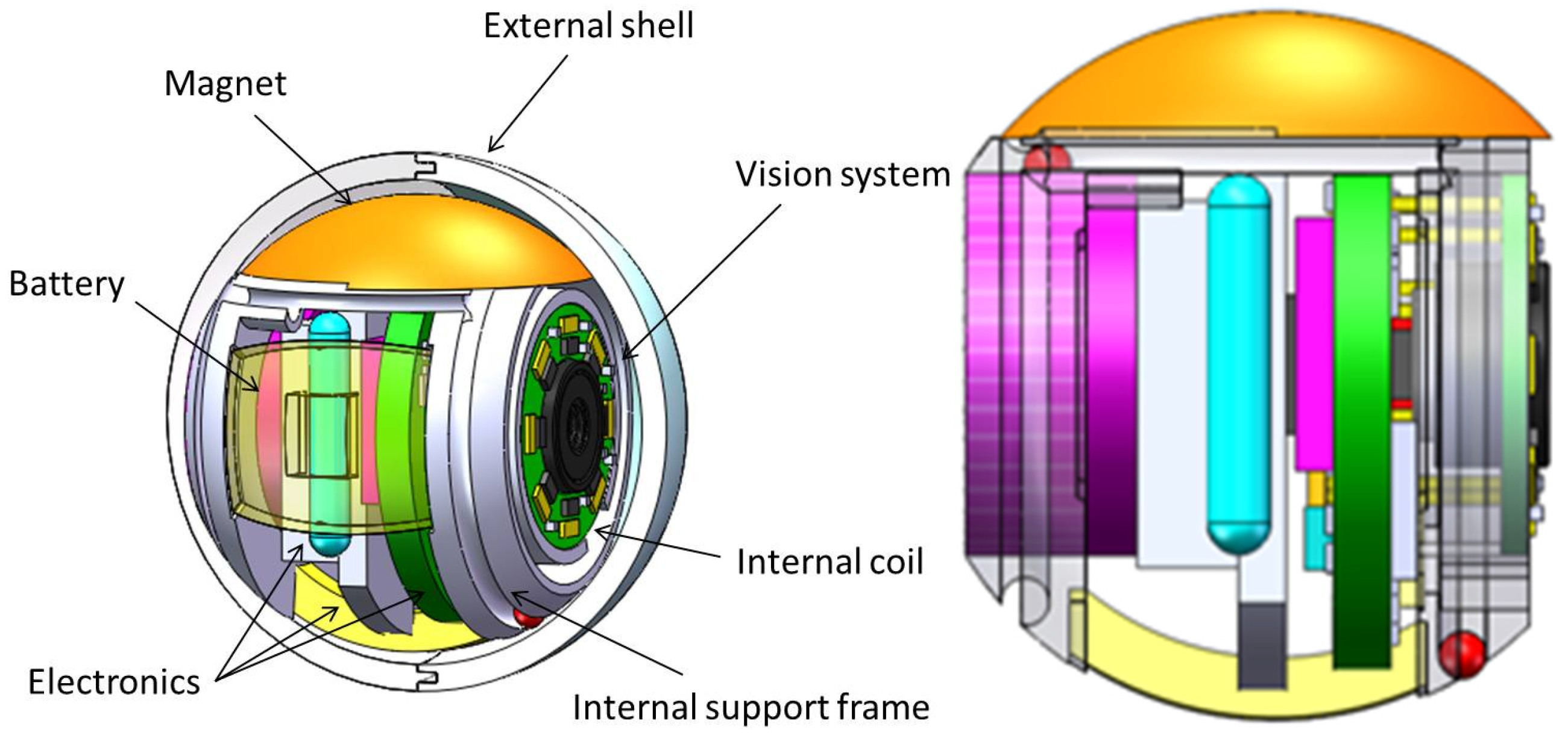
2.1. Endoscopic Capsule Case Study

The innovative capsule was conceived as an assembly of two concentric spheres, which can mutually rotate with low-friction resistance, enabling a dynamic system with 3 degrees of freedom (i.e., rotations around the three main axes) [7]. While the outer body is a hollow transparent sphere, the inner structure (i.e., the internal support frame) on which all components are anchored was conceived as a single body allowing the integration of electronics, battery and the internal magnetic source for locomotion (i.e., the internal permanent magnet). The integrated battery, the Varta CP1254, was the best compromise between small dimensions (12.1 mm diameter, 5.4 mm height and 1.2 g weight), voltage and medical requirements. The inner body is a frame that allows innovative coupling, ensuring a 360° rotation of the inner body with respect to the external shell. The motion of the capsule is obtained by ensuring the rotation of the frame with respect to the external shell, and the advantage of the internal frame in terms of anchor points. The diameter of the external shell is 23 mm; it is a compatible dimension for insertion into the rectum for wireless colonoscopy. The concept is shown in Figure 1 with all internal components indicated. In particular, the internal coil is positioned inside a cylindrical support having 13.5 mm internal diameter, 15.5 mm external diameter and 2.8 mm height.
Figure 1. The capsule prototype concept with embedded components (Left); lateral view (Right).
Energies 08 10315 g001
Considering the characteristics of the proposed endoscopic capsule that is inserted into the rectum for performing minimally invasive colonoscopy, fast off-line battery recharging was implemented to allow the capsule to be reused as in the case of traditional endoscopes. Previous works have introduced methods for the theoretical calculation of the inductive coupling coefficient (k) and mutual inductance (M) dependence on different geometries of coils and positions between two coils [12,13,14,15]. The induced voltage of the receiver coil for radio frequency identification applications has been calculated as well, resulting in non-suitable coil sizes for devices with inside-body application. The reason for this is that in real applications of wireless transfer between human tissues, energy from a power coil undergoes inevitable tissue energy loss. In this kind of application, size and distance constraints impose limits on coil geometries, as well as on the amount of power that must be transferred from the transmitter to the receiver system. If the relative position between the two coils is maintained fixed, their surrounding environment is the air and the system does not require the power amplifier to be optimised; therefore, total system efficiency is not compromised. For this reason, a near field resonant inductive coupling was preferred and a parallel resonance for the secondary circuit was chosen, as proposed in [16].
The aim of the off-line wireless recharging approach of this work is to offer a more practical solution than that applied to endoscopic capsules and to provide a new methodology for the design of endoscopic capsules with embedded rechargeable batteries, paving the way to the integration of more advanced (and costly) on-board vision and sensing systems and allowing the endoscopic capsules for colonoscopy to be reused such as with traditional colonoscopes.

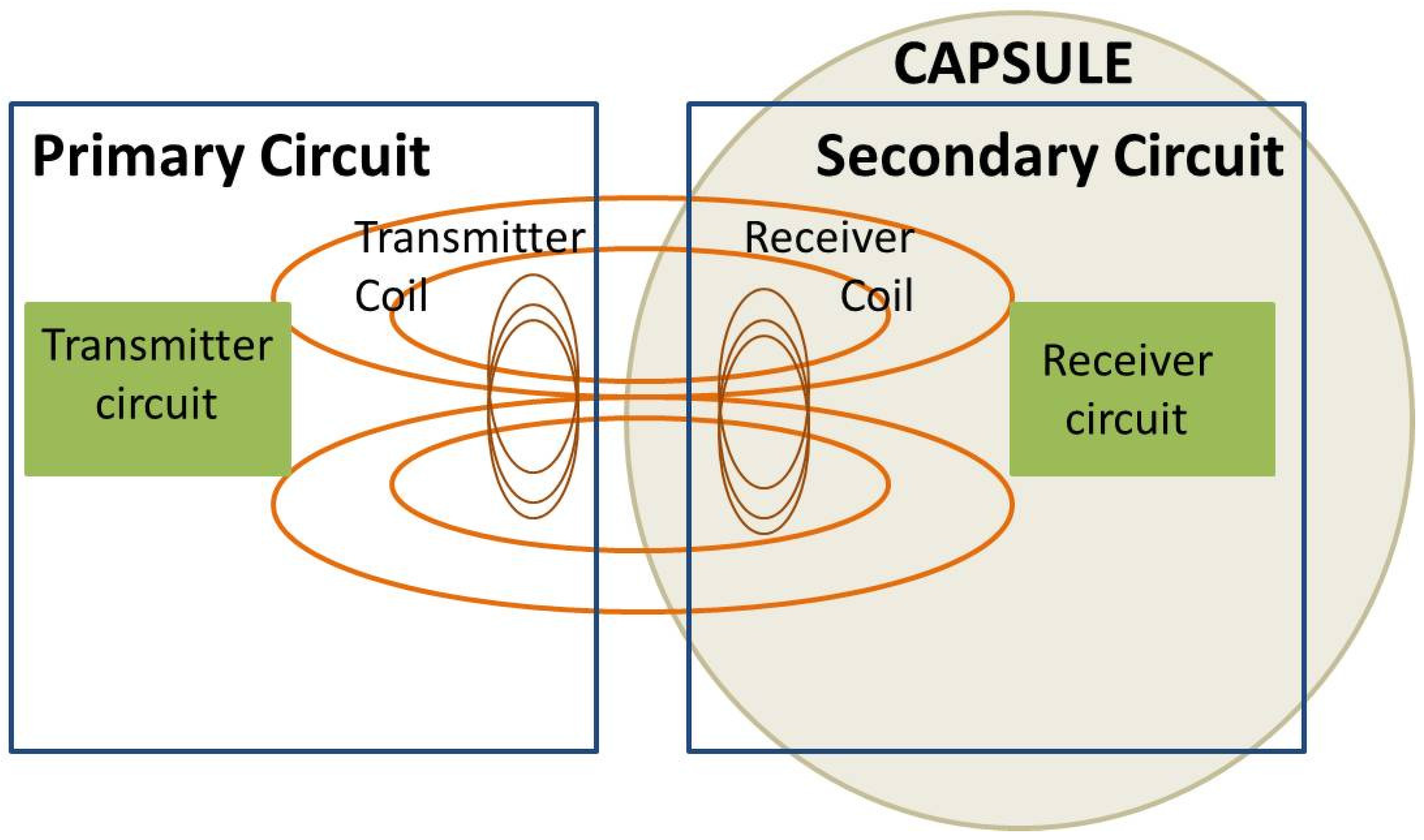
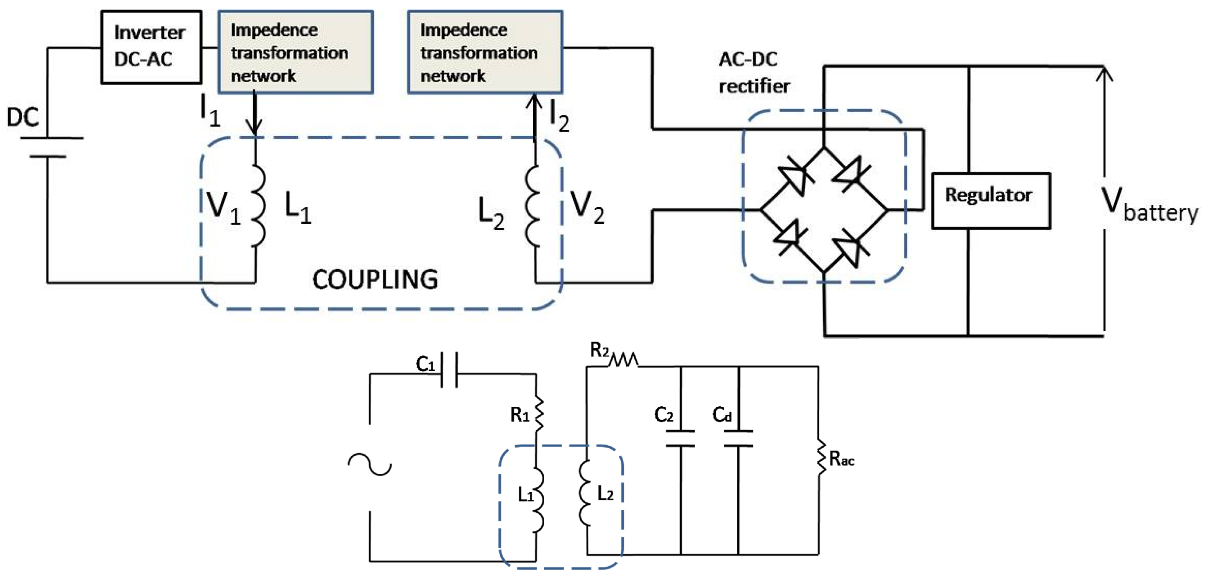
3. Implementation of the Wireless Recharging System

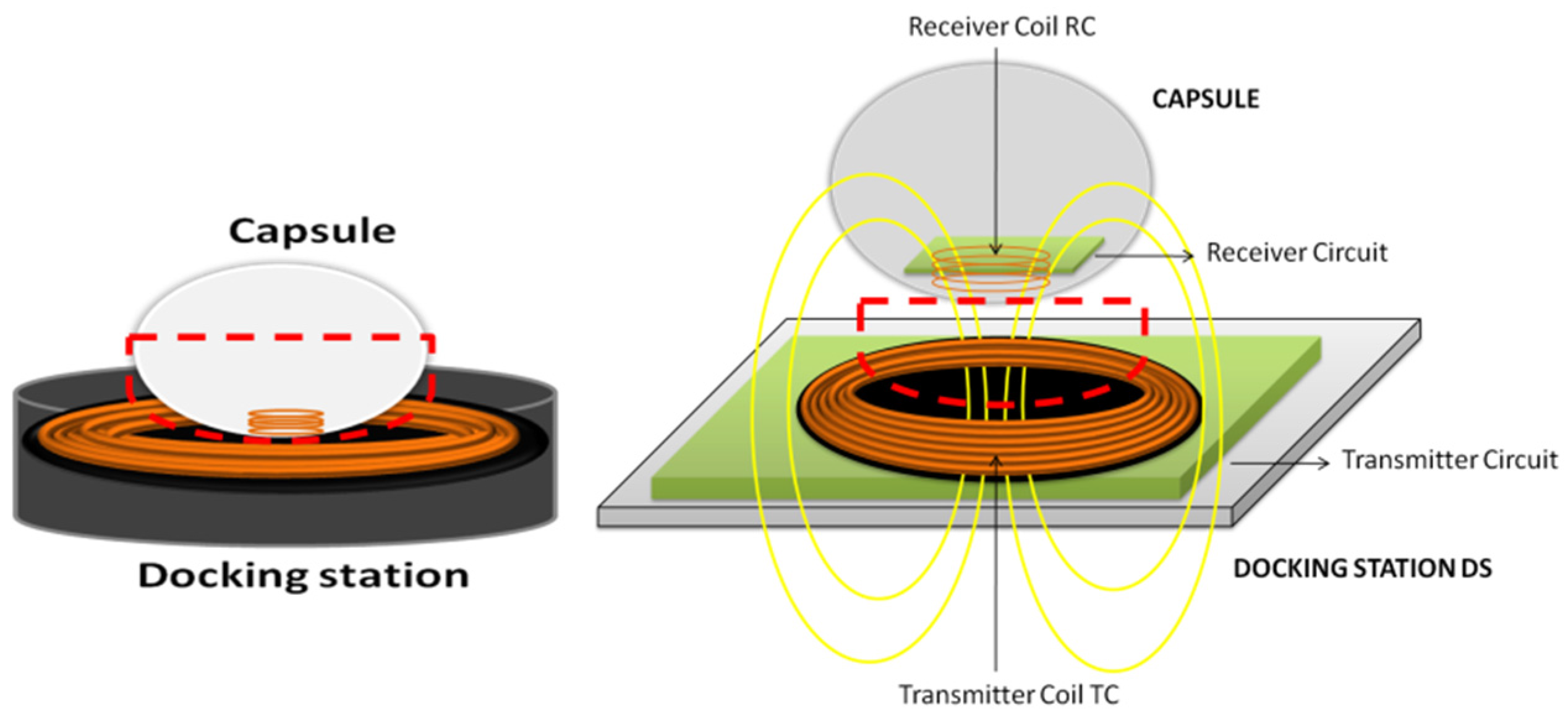
3.1. Design Overview

The proposed wireless battery recharging system is based on resonant coupling electromagnetic induction. Inductive resonant coupling is a form of inductive coupling in which power is transferred by magnetic fields between two resonant circuits: the transmitter and the receiver. Each resonant circuit consists of a coil connected to a capacitor. The transmitter and receiver coils are tuned to resonate at the same resonant frequency. In the proposed system, the transmitter consists of a primary circuit, which includes the transmitter circuit and the transmitter coil, external to the capsule, while the receiver consists of the receiver coil and secondary circuit, on board the capsule. The transmitter coil sends energy to the capsule, through the receiver coil that stores the energy in the capsule battery (Figure 2).
Figure 2. Schematic concept for wireless power recharging system.
Energies 08 10315 g002
The proposed system is a typical system, called near-field or non-radiative, in which power is transferred over short distances by magnetic fields using inductive coupling between the two coils. The underlying principle behind wireless charging is Faraday’s law of induced voltage, commonly used in motors and transformers [17,18]. In this work, the near-field inductive coupling based charging system was applied for the first time in an endoscopic capsule. The primary and secondary circuits and their coils were designed and manufactured with the aim to satisfy the VARTA CP 1254 battery requirements in terms of current and voltage recharge requests (Table 1), in view of the fact that the dimensions of the receiving coil are limited by the support for the internal coil inside the capsule. Other batteries were considered but were not used in this application. It is worth noting that the proposed system for wireless recharging can be applied to any battery-powered system.
Table 1. Capsule battery requirements.
Battery TypeCapacity C [mAh]Max. Continuous discharge current [mA]Pick current [mA]Dimensions [mm3]Weight [g]Supply [V]Charge Voltage [V]Charge Current [mA]
VARTA CP 1254Rechargeable Lithium button Cells50100 mA150@2s12.1(Ø) × 5.41.63.74.20.5 C 25mA
Table 2. Receiver coil features.
Coil TypeWiredoutdinlNumber of TurnsNumber of Layers Energies 08 10315 i001
Receiver coilMulti-layer spiral coilAWG 2915.5 mm13.5 mm3 mm12 (6 per layer)2
In particular, the required charge voltage is 4.2 V, while the optimal charge current is 0.5 C (25 mA), thus requiring a total power of at least 105 mW.

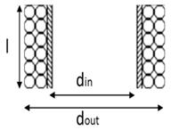
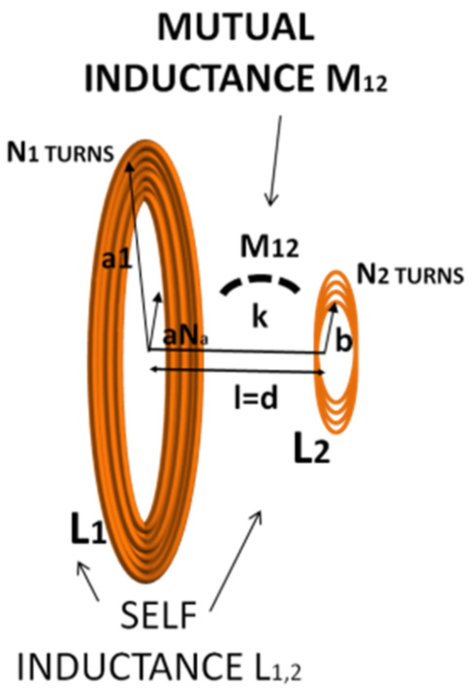
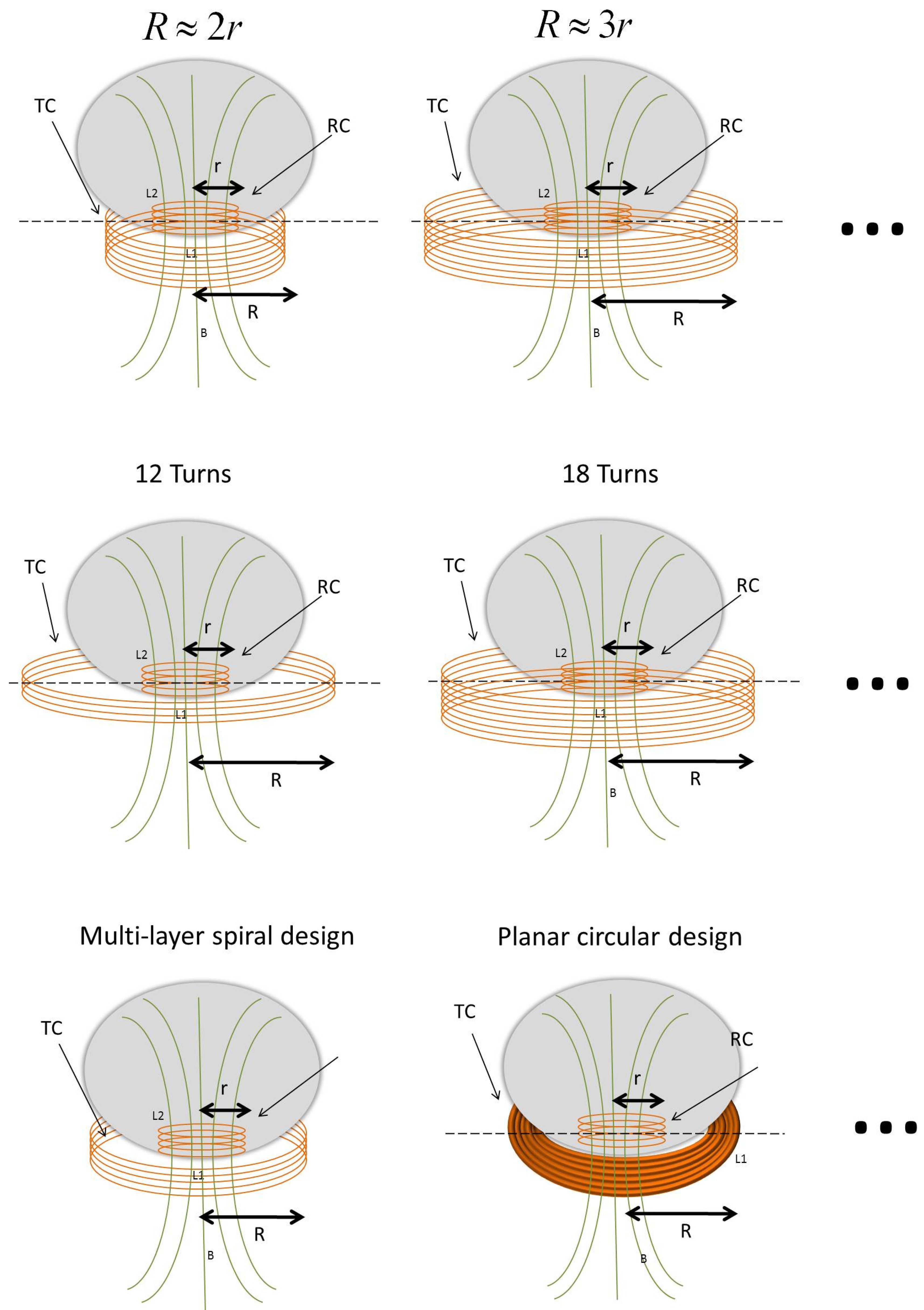
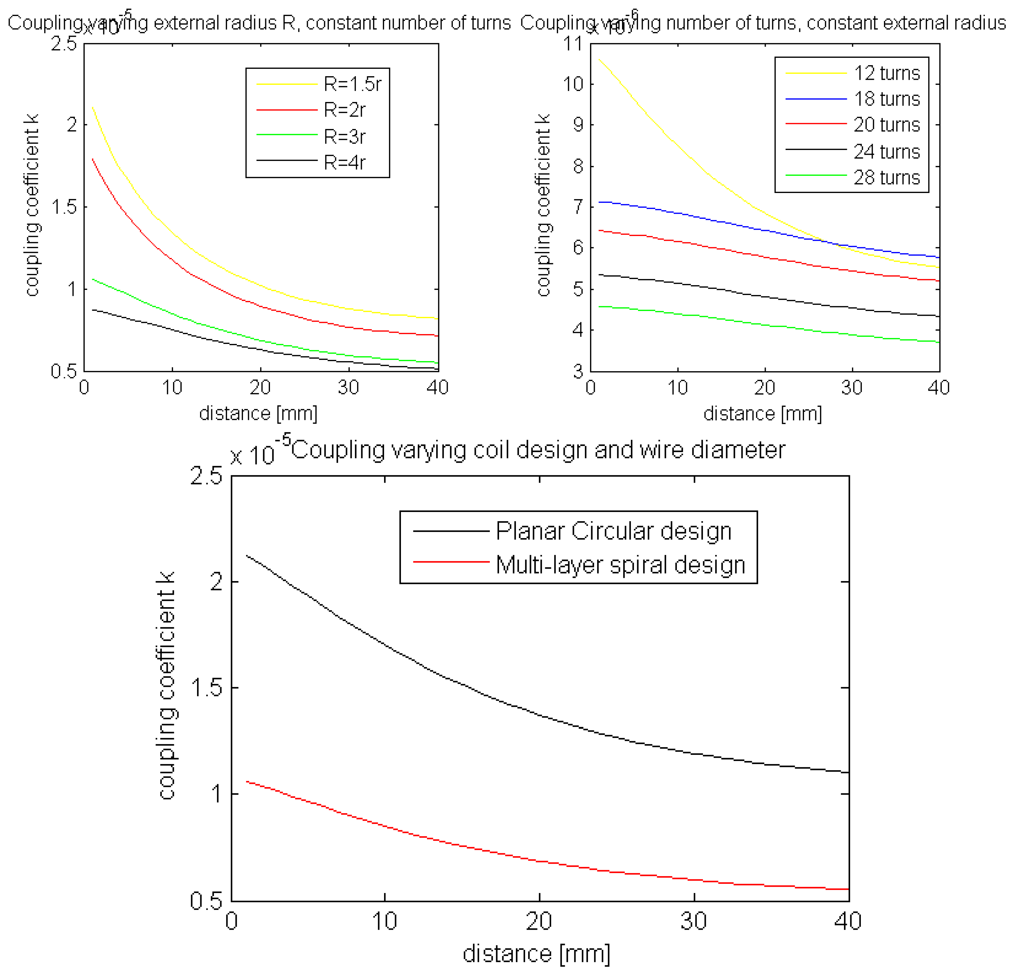
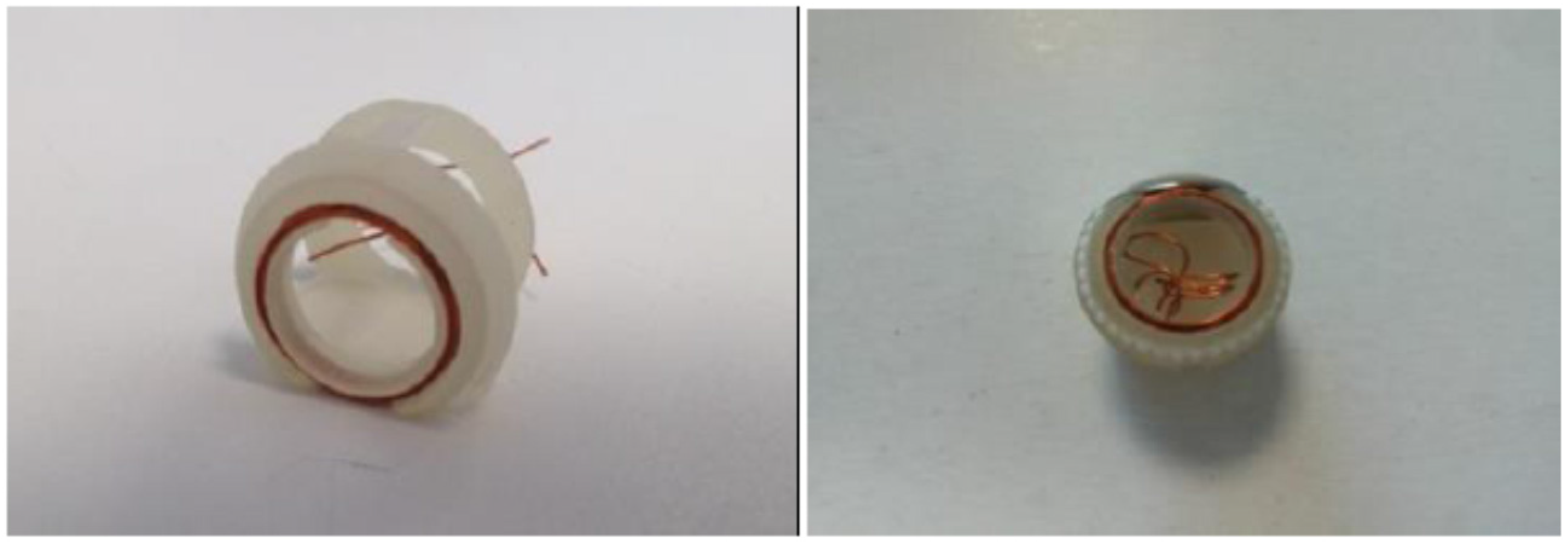
3.2. Receiver and Transmitter Coil Design

The first step when designing a wireless recharging system is the design of the coils in order to maximize the coupling coefficient between the two coils, including:
  • optimization of the coil geometry with respect to the given constraints;
  • external coil geometry;
  • type and size of wire used;
  • number of turns;
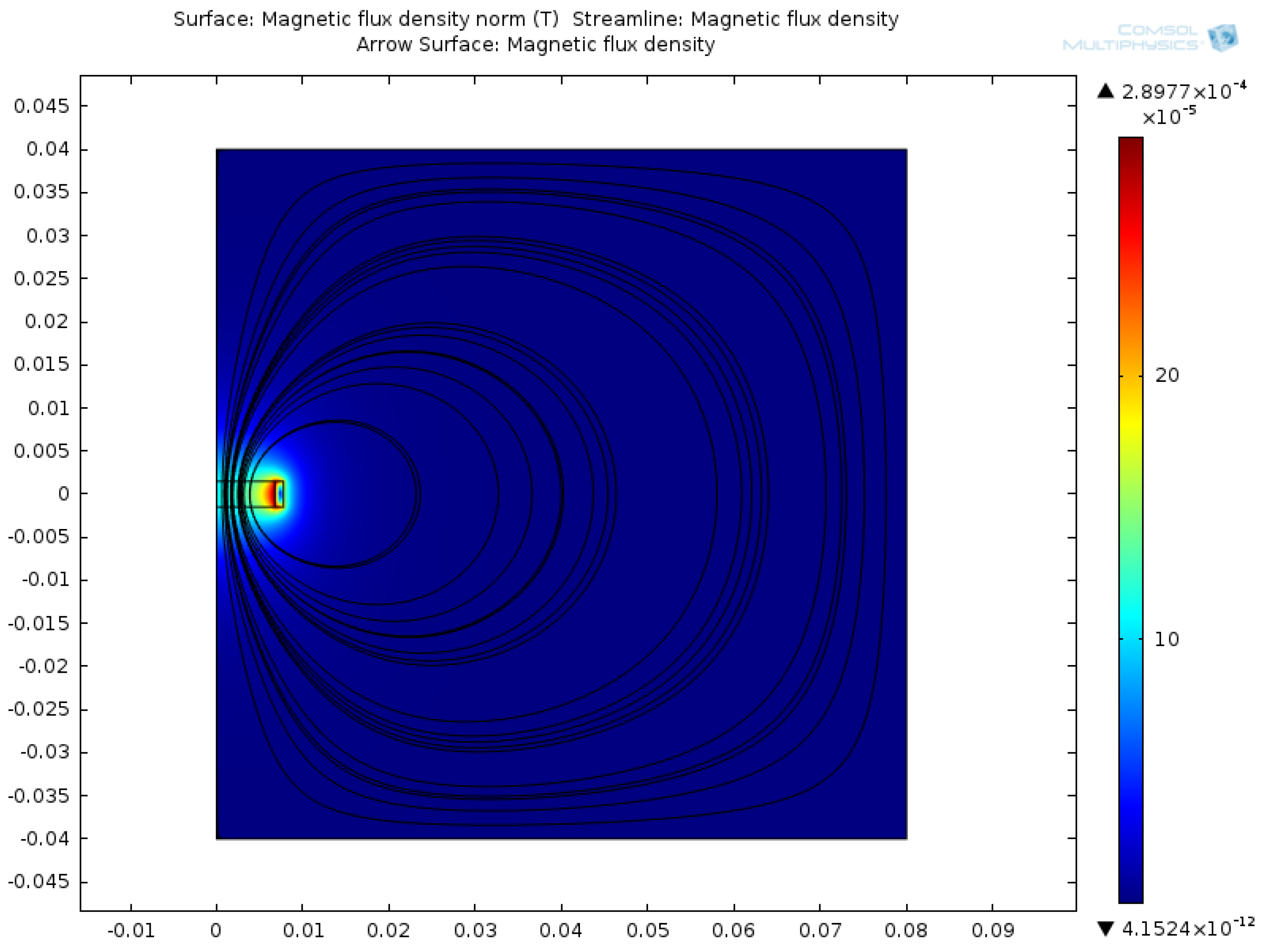
  • analysis of the magnetic field generated by the two coils.
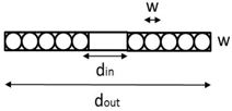
Indeed, the performance of the proposed near-field wireless power system strictly depends on the electromagnetic properties of the primary and secondary coils. In particular, the magnetic fields produced by each coil, coil self-inductance and the mutual inductance between the two coils are critical. The internal coil included in the internal coil support of the capsule was defined first. Then, the external coil was designed so that its dimensions would not induce electromagnetic disturbances against other medical devices used in a medical scenario, and so that the system could be entirely portable.
In order to maximize the Ampere *Turns and the related magnetic field generated by the receiving coil, a spiral multilayer design was preferred. An analysis in Matlab was implemented considering the number of turns and number of layers based on the dimensional constraints of the receiving coil support (13.5 mm internal diameter, 15.5 mm external diameter and 3 mm height). An AWG 29 wire was chosen because of its small diameter (0.286 mm diameter and 0.0646 mm insulating layer).
In theory, in the case of a multilayer spiral coil having such dimensions and Φ (wire diameter) of 0.286 mm, the maximum number of turns and layers are 33 and 3 respectively. However, due to manual manufacturing of the internal coil, the receiving coil is characterized by two layers and 12 turns (6 per layer), an external diameter of 15.5 mm and an internal diameter of 13.5 mm as shown in Table 2. These size constraints are due to the shape of the internal capsule frame (Figure 1). The improved performance of the internal coil once the procedure is automated is not described in this paper.
In order to optimize inductive coupling between the receiver coil and a transmitter coil, different external coil designs were considered in terms of wire diameter, number of turns and geometry. According to Equation (1), the coupling coefficient k depends on the geometry of the coils, their relative spacing and the medium surrounding them (air in this case).
A detailed analysis was performed in terms of transmitting coil geometry, including number of turns, wire diameter and typology. FEM simulation values obtained using Comsol Multiphysics were used to assess the correctness of the calculated MATLAB values, which were taken as reference.
In the near field, the mutual distance between the transmitter and the receiver coils must be smaller than the wavelength. The design of the transmitter coil can be developed flexibly in terms of size because the transmitter coil has not the same limitations of the receiver coil in terms of shape and geometry due to the capsule dimensions. Figure 3 shows the proposed system in which circular coils are perfectly aligned in a relative fixed position.
Figure 3. Transmitter (on the left) and receiver (on the right) coils perfectly aligned in a relative fixed position.
Energies 08 10315 g003
The coupling factor or coefficient k between two inductively coupled coils L1 and L2 and mutual inductance M12 is defined as:
k =   M 12 L 1 L 2
The mutual inductance, M12, between two coils with N1 and N2 numbers of turns, respectively, l the distance from segment l1 of the transmitter coil to segment l2 of the receiver coil and μ the medium magnetic permeability between the coils, can be described by the Neumann formula [19]:
M 12 =   µ N 1 N 2 4 π   c 1 c 2 d l 1 · d l 2 l
This equation, from Maxwell equation for transmitter and receiver circular concentric loops with radii a and b, respectively, distance d and lateral misalignment Δ becomes [20]:
M 12 ( a , b , Δ , d )   =   π µ a b 4 π   0 J 1 ( x a b ) · J 1 ( x a b ) · J 0 ( x Δ a b ) e (   x Δ a b ) d x
where J0 and J1 are the Bessel functions of the zero-th and first order, respectively. According to the proposed application, for perfectly aligned coils with no lateral misalignment, we can define:
M 12 ( a , b , Δ = 0 , d )   =   2 µ a b α [ ( 1 α 2 2 ) K ( α ) E ( α ) ]
with:
α = 2 a b ( a + b ) 2 + d 2
Also, K(α) and E(α) the elliptic integrals of the first and second order. Finally, considering two circular coils with N1 and N2 turns, respectively, M12 is:
M 12 = i = l N 1 i = l N 2 M 12 ( a i , b j , d )
According to Equation 1, the coupling factor equation also needs the self-inductance value of each coil. For a single turn circular coil, self-inductance can be described through the approximation:
L ( b , Φ )   =   µ 0 b [ ln ( 8 b Φ ) 2 ]
with Φ the wire radius, µ0 the magnetic permeability of the medium (air in this application) and b the radius of the coil.
For a multi-turn coil, the self-inductance is the sum of the self-inductance of each turn as well as the mutual inductance between turns [20], as indicated below:
L t o t =   i = 0 N L i +   M i j ( 1 δ i j )
with:
δ i j = 1   i f   i = j   a n d   δ i j = 0   i f   i   j
Instead, an expression that approximates the inductance of planar circular coil [21] is given by:
L 1 =   µ 0 N 2 d a v g C 1 2 ( ( ln c 2 ρ ) + C 3 ρ + C 4 ρ 2   )
with:
ρ = d o u t d i n d o u t + d i n ;   C 1 = 1 ;   C 2 = 2.46 ;   C 3 = 0 ;   C 4 = 0.20
In order to evaluate the correctness of the calculated theoretical values, several simulations using Comsol Multiphysics software were performed.
The calculated values obtained with a Matlab implementation of the equations above were compared with the simulated values derived from Comsol simulation. The magnetic field generated by the coils and the total magnetic energy considered for calculating the self-inductance were simulated. Figure 4 shows the magnetic field generated by the receiver coil.
Figure 4. Magnetic flux density obtained from simulation of the receiver coil.
Energies 08 10315 g004
Indeed, based on the total magnetic energy Wm, generated by a current I0 passing through a coil, it is possible to calculate the self-inductance of the coil Li as follows:
L i = 2 W m I 0 2
In order to optimize the coupling between the transmitter and the receiver coil, different transmitter coil geometries were considered. Multi-turn layer spiral and planar flat circular geometries were analyzed and theoretically calculated in terms of self-inductance, mutual inductance and coupling factor.
Considering internal coil size constraints, optimization was mainly related to the identification of optimal external coil parameters. Various external coil parameters were considered such as diameter, number of turns and coil geometry. The optimization of the external coil was obtained step-by-step, by changing one parameter at a time, as reported below.
Figure 5 shows some examples of manufactured coil schematics with varying external diameter, number of turns and coil design. Manufactured coils include among others: multilayer coil design with an external radius of 11.6 mm, 15.5 mm, 23.25 mm, and 31 mm, keeping the number of turns constant to 12; multilayer coil design with a 15.5 mm constant external radius and increasing number of turns (from 12–32); flat planar spiral coil with a radius of 23.25 mm.
Figure 5. Examples of explored transmitter coils. RC (receiver coil) and TC (transmitter coil) are indicated.
Energies 08 10315 g005
A shown in Figure 6, the coupling factor k decreases with axial spacing (the distance between the two coils in the axial direction) and decreases as the radius and number of turns of the transmitter coil increase. A planar circular design increases the coupling factor with respect to the spiral multi-layer design.
Figure 6. Trends of k depending on the distance between the two coils by varying: external radius keeping the number of turns constant (Top-Left); number of turns keeping the external radius constant (Top-Right); coil design (Bottom).
Energies 08 10315 g006
On the basis of the above considerations, a single layer planar circular transmitter coil, made with AWG 18 wire and characterized by 10 turns, an external diameter of 42.61 mm and an internal diameter of 20.81 mm, was fabricated (Table 3). In order to increase the efficiency of the system, a Ni-Zn shielding disk (50 mm external diameter, 5 mm internal diameter and 1 mm thickness) was used. Essentially, there are no dimensional constraints for the transmitter coils, but the obtained dimensions were chosen in order to better design the docking station and maximize the coupling between the spherical capsule and the docking station itself.
After manufacturing the two coils, the calculated, simulated and measured self-inductance values were analyzed. The calculated transmitter and receiver coil self-inductances were L1 = 3.9 µH and L2 = 3.4 µH, respectively. The simulated and measured values (using an Avo Megger B131 LCR meter) are reported in Table 4. These values are comparable with the calculated values, thus confirming the reliability of the calculated theoretical value used for the coupling coefficient calculation.
Table 3. Transmitter coil features.
Coil TypeWiredoutdinlNumber of TurnsNumber of Layers Energies 08 10315 i002
Transmitter coilPlanar circular coilAWG 1842.61 mm20.81 mm-10Single
Table 4. Self-inductance of transmitter and receiver coils.
Self-inductance (measured)Self-inductance (calculated)Self-inductance (simulated)
Transmitter coil3.6 µH 3.95 µH 3.84 µH
Receiver coil3.3 µH3.45 µH3.36 µH
It is worth noting that the simulated self-inductance of transmitter and receiver coils appropriately reflects the behavior of the manufactured coils with respect to the calculated theoretical values. The use of simulation results could represent the best solution in the future for designing coils for custom wireless recharging systems.
Based on the outcome from the transmitter and receiver coils, the corresponding circuits were designed, as reported in Section 3.3.

3.3. Overview of Internal and External Circuits

Once the most suitable coil configuration had been defined, a receiver (internal) circuit and a transmitter (external) circuit were designed and fabricated in order to satisfy the battery requirements.
The power generated by the transmitter side as a magnetic flux was induced to the receiver side, enabling the receiver circuit to collect the incoming power. A parallel resonant circuit was selected to achieve optimal coupling efficiency. By using resonant coupled coils, the efficiency of inductive power transfer can be increased, especially by placing the inductors in a resonant LC circuit. For low coupling factors (and consequently low link efficiency), the series resonant topology needs very high secondary coil inductance values to achieve optimum coupling efficiency [16]. This is not possible due to size limitations for the receiver coil, described previously. Indeed, low power links usually use secondary parallel resonance, making the LC tank act as a voltage source. In the chosen parallel case, a parallel resonator was used. For parallel resonant topology, ceramic chip capacitors were adopted. A typical circuit for inductive power transfer is shown in Figure 7 (Top) with the AC model used for analysis (Figure 7 Bottom). Cd represents the capacitance added by the rectifier, while RAC is the AC equivalent resistance of AC-DC rectifier. Parasitic resistances R1 and R2 of the transmitter and receiver coils respectively are represented.
Figure 7. Top: typical series resonant coupling circuit; Bottom: AC model of typical series resonant circuit including parasitic resistances of the coils.
Energies 08 10315 g007
The external charging system was powered by an input DC voltage of 5 V coming from a USB port. A switched transistor bridge using two field-effect transistors (FETs) drove the transmitter coil and series capacitor. A resonant frequency of 163 KHz was set by means of the series capacitor. The induced power was coupled to the wireless power receiver through the receiver coil which collects the incoming power. The receiver rectifies the power by means of diode rectifiers, including FETs for improving the efficiency. The output power was filtered using ceramic output capacitors, and was then applied to the battery that needed to be charged, through a regulator.

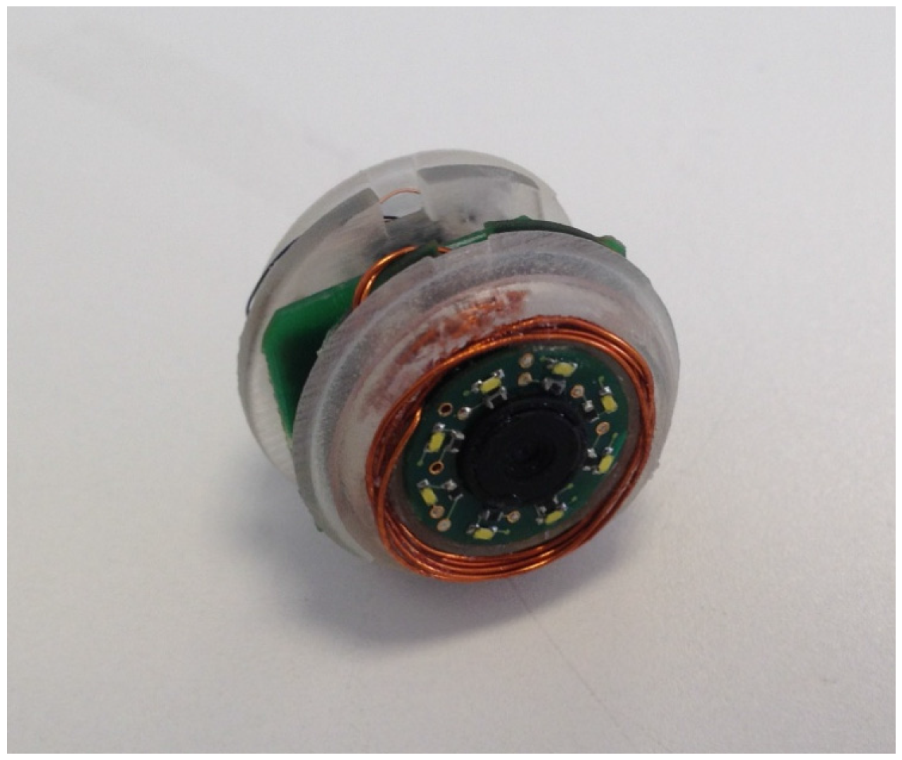
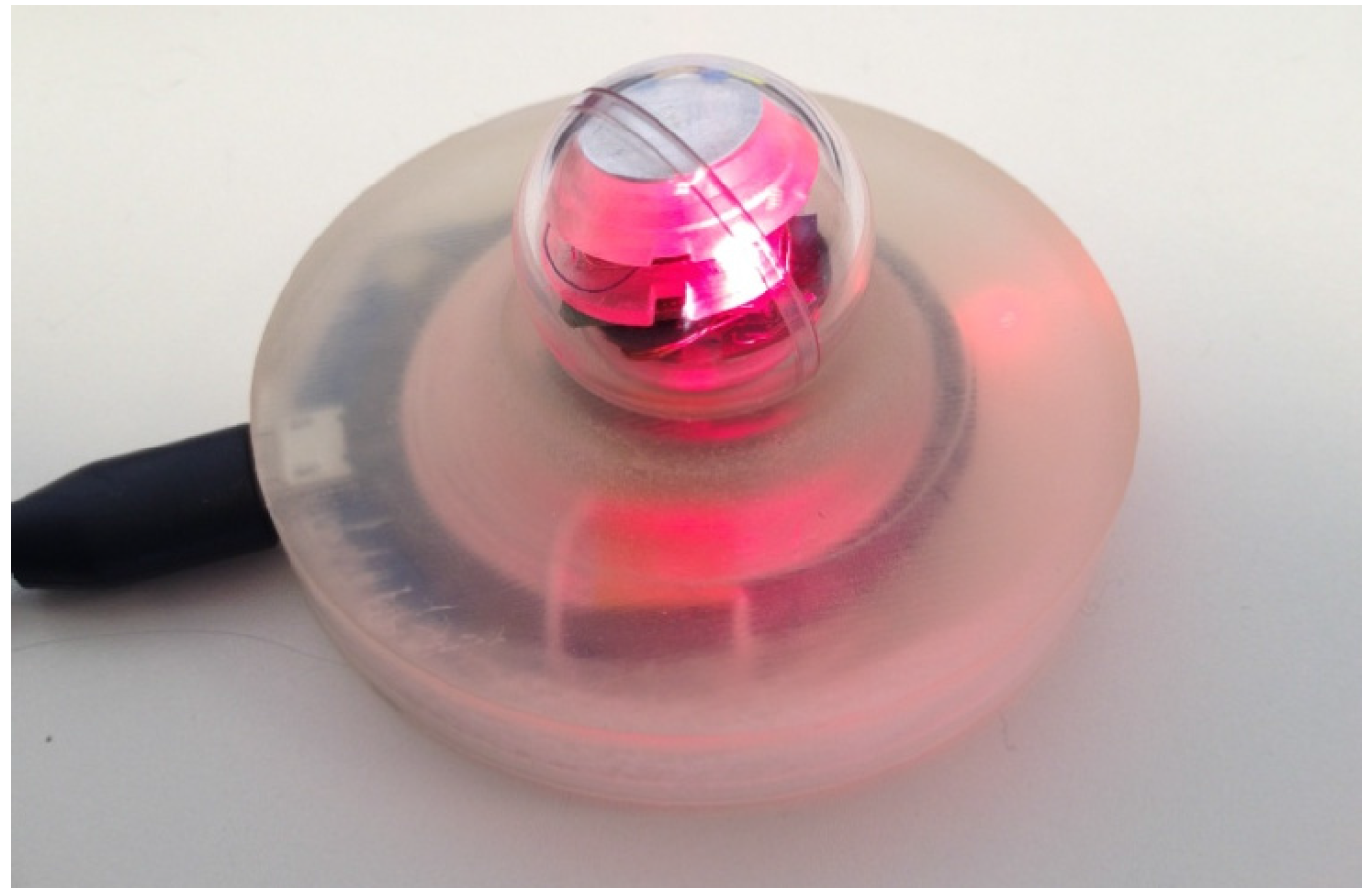
4. System Integration

System integration was aimed at integrating the wireless power recharging system into the endoscopic capsule, according to the scheme reported in Figure 8.
Figure 8. Schematics of the intended operation for the capsule recharging system: docking station (Left) and coupling between internal and external coils (Right).
Energies 08 10315 g008
Integration of the wireless recharging system was essential to demonstrate the proof of concept and the feasibility of the approach in an active endoscopic capsule, thus allowing the diagnostic use of the delivered images. To this purpose, the coils were manufactured according to the design parameters, together with integration within the capsule (Figure 9).
Figure 9. Manufactured receiver coil integration within the capsule.
Energies 08 10315 g009
The final capsule prototype including the wireless recharging system was then integrated. Integration of the wireless recharging system into an existing endoscopic capsule was challenging if considering all the electronics parts that needed to be included in the small internal support frame. The wireless recharging systems circuits were integrated inside the capsule, together with other miniaturized electronics according to the scheme reported in Figure 1. The result of the integration is shown in Figure 10.
Figure 10. Capsule with integrated wireless recharging system.
Energies 08 10315 g010
Theoretical considerations related to the implementation of the wireless recharging system, the implementation itself and possible integration in the endoscopic capsule for colonoscopy have been described. Moreover, the capsule integrates additional components, such as the battery, the hemispheric permanent magnet used for capsule actuation and an RFID tag for localization purposes. The presence of other electronic components and the capsule permanent magnet do not affect the possibility of recharging the capsule because of the short distance between the internal and external coils (5.2 mm) compared to the distance between the capsule permanent magnet and the internal coil (13.63 mm).
The docking station was designed to allow the wireless recharging of the capsule while ensuring it is air and liquid tight. The need for cables was eliminated as well. In detail, when the capsule is positioned on the docking station, the input voltage is converted into a high frequency alternating current. The alternating current induces a time varying magnetic field in the transmitter circuit, which extends to the receiver circuit within a specified distance. The magnetic field generates current within the receiving circuit through a resonant coupling process in which both coils resonate at the same frequency. The docking station allows optimal alignment of the transmitter and receiver coils according to design specifications. As soon as the capsule is positioned on the docking station, the battery inside the capsule receives the power and charges up. A LED indicates that the capsule is charging, as shown in Figure 11.
Figure 11. The capsule with integrated wireless recharging system charging on the dedicated docking station.
Energies 08 10315 g011

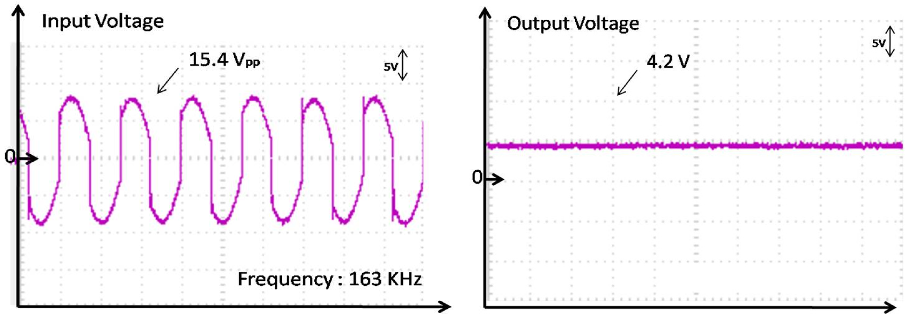
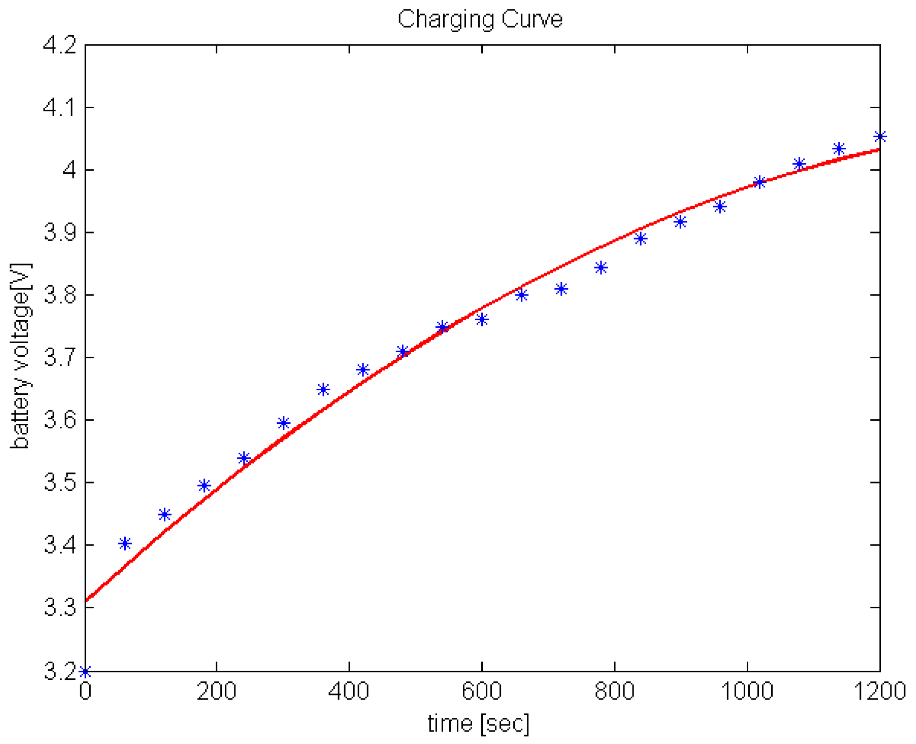
5. Experimental Results

Experiments were conducted to assess the results of the recharging process, by measuring the involved signals from the transmitter and receiver circuits. The signal was generated by an input voltage of 5 V via USB that was transferred wirelessly to the receiver circuit. The driving voltage on the transmitter circuit is shown in Figure 12, Left.
Figure 12. Voltage signal on the transmitter circuit (Left) and output voltage on the battery (Right).
Energies 08 10315 g012
With the current design of the wireless recharging system, a voltage of V1 = 15.4 V on the transmitter coil was available with a current of I1 = 500 mA. These values resulted in a final output voltage Vbattery of 4.2 V (Figure 12 Right) on the battery with 250 mA current (output power of 1050 mW). The efficiency of the wireless recharging system, therefore, is around 13%, as a compromise between inductive coupling and quality factors. Once the engineered version of the capsule is ready, industrial manufacturing of the coil can be performed, improving inductive coupling and quality factors of the coils and overall system efficiency by up to 50%–60% (thus reducing the recharging time or decreasing the overall required power).
The integrated hardware allows the internal capsule to couple with the external one, making wireless recharging possible in about 20 min from 3.2–4 V, as shown in Figure 13. The charging curve was experimentally obtained by using the wireless recharging system and measuring the battery voltage with a voltmeter.
Figure 13. Typical charging curve using the wireless recharging system.
Energies 08 10315 g013

6. Conclusions

The developed system is able to charge the battery of the endoscopic capsule in a completely wireless manner and to make the capsule completely tight for sterilization and further use. The wireless recharging system consists of a charging station, which represents the cradle the capsule is placed inside, specifically designed for improving the alignment between the external planar coil and the internal one. The capsule with integrated recharging system can be recharged in 20 min with a power of about 1 W. This paper has introduced a general design principle for integrating a dedicated recharging system in endoscopic capsules and making them reusable after proper and fast sterilization as usually happens in the case of traditional endoscopes. The proposed system will allow the costs related to each procedure to drop below 80 €, considering that each capsule may be used six times, and will made the endoscopic capsule procedures competitive in terms of costs with respect to both traditional procedures. By including a wireless recharging system, more expensive and high-performance technology for vision systems can be included in endoscopic capsules, thus improving the quality of minimally invasive endoscopic procedures that could gradually replace traditional ones. The wireless recharging system proposed in this work was applied to an innovative spherical capsule designed to allow safe, accurate and effective active locomotion along the colonic lumen after insertion into the rectum. The recharging system may also be applied to other devices and endoscopic capsules in order to enhance the lifecycle in terms of the number of times the single device is used and the reduction of related costs.

Acknowledgments

This work was partially supported by the SUPCAM FP7 European project FP7-SME-2012-315378.

Author Contributions

Paolo Dario was invited to write a paper for his experience in capsule endoscopy field; Arianna Menciassi set the paper structure and lead the work; Gastone Ciuti reviewed the first version of the paper; Francesca Mulana introduced the concept, took care of the theoretical and simulated models, performed the experiments and built the first wireless recharging prototype; Giuseppe Tortora defined the steps to implementation, helped with manufacturing prototypes and capsule integration. Giuseppe Tortora and Francesca Mulana wrote the paper.

Conflicts of Interest

The authors declare no conflict of interest.

References

  1. Toennies, J.L.; Tortora, G.; Simi, M.; Valdastri, P.; Webster, R.J., III. Swallowable medical devices for diagnosis and surgery: The state of the art. J. Mech. Eng. Sci. 2010, 224, 1397–1414. [Google Scholar] [CrossRef] [Green Version]
  2. Waterman, M.; Eliakim, R. Capsule enteroscopy of the small intestine. Abdom. Imaging 2009, 34, 452–458. [Google Scholar] [CrossRef] [PubMed]
  3. De Falco, I.; Tortora, G.; Dario, P.; Menciassi, A. An Integrated System for Wireless Capsule Endoscopy in a Liquid-Distended Stomach. IEEE Transact. Biomed. Eng. (TBME) 2013, 61, 794–804. [Google Scholar] [CrossRef] [PubMed]
  4. Tortora, G.; Valdastri, P.; Susilo, E.; Menciassi, A.; Dario, P.; Rieber, F.; Schurr, M.O. Propeller-based wireless device for active capsular endoscopy in the gastric district. Minim. Invasive Ther. Allied Technol. (MITAT) 2009, 18, 280–290. [Google Scholar] [CrossRef] [PubMed]
  5. Arezzo, A.; Menciassi, A.; Valdastri, P.; Ciuti, G.; Lucarini, G.; Salerno, M.; Di Natali, C.; Verra, M.; Dario, P.; Morino, M. Experimental assessment of a novel robotically-driven endoscopic capsule compared to traditional colonoscopy. Dig. Liver Dis. 2013, 45, 657–662. [Google Scholar] [CrossRef] [PubMed]
  6. Ciuti, G.; Valdastri, P.; Menciassi, A.; Dario, P. Robotic magnetic steering and locomotion of capsule endoscope for diagnostic and surgical endoluminal procedures. Robotica 2010, 28, 199–207. [Google Scholar] [CrossRef]
  7. Lucarini, G.; Ciuti, G.; Mura, M.; Rizzo, R.; Menciassi, A. A new concept for magnetic capsule colonoscopy based on an electromagnetic system. Int. J. Adv. Robot. Syst. 2015. [Google Scholar] [CrossRef]
  8. Carta, R.; Tortora, G.; Lenaerts, B.; Thoné, J.; Valdastri, P.; Menciassi, A.; Dario, P.; Puers, R. Wireless powering for a self-propelled endoscopic capsule. Biosens. Bioelectron. 2009, 25, 845R–851R. [Google Scholar] [CrossRef] [PubMed]
  9. Carta, R.; Lenaerts, B.; Thoné, J.; Tortora, G.; Valdastri, P.; Menciassi, A.; Puers, R.; Dario, P. Wireless power supply as enabling technology towards active locomotion in capsular endoscopy. In Proceedings of the Eurosensors XXII, Book of abstracts, Dresden, Germany, 7–10 September 2008; pp. 1369–1372.
  10. Basar, M.R.; Ahmad, M.Y.; Cho, J.; Ibrahim, F. Application of wireless power transmission systems in wireless capsule endoscopy: An overview. Sensors 2014, 14, 10929–10951. [Google Scholar] [CrossRef] [PubMed]
  11. Xin, W.; Yan, G.; Wang, W. Study of a wireless power transmission system for an active capsule endoscope. Int. J. Med. Robot. Comput. Assist. Surg. 2010, 6, 113–122. [Google Scholar] [CrossRef] [PubMed]
  12. Flack, F.C.; James, E.D.; Schlapp, D.M. Mutual inductance of air-cored coils: Effect on design of radio-frequency coupled implants. Med. Biol. Eng. 1971, 9, 79–85. [Google Scholar] [CrossRef]
  13. Chen, S.C.Q.; Thomas, V. Optimization of inductive RFID technology. In Proceedings of the Electronics and the Environment, Denver, CO, USA, 7–9 May 2001; pp. 82–87.
  14. Salim, A.; Baldi, A.; Ziaie, B. Indutive link modeling and design guidelines for optimum power transfer in implantable wireless microsystems. In Proceedings of the 25th IEEE EMBS, Cancum, Mexico, 17–27 September 2003; pp. 3368–3371.
  15. Heetderks, W.J. RF powering of millimeter- and submillimeter-sized neural prosthetic implants. IEEE Trans. Biomed. Eng. 1988, 35, 323–327. [Google Scholar] [CrossRef] [PubMed]
  16. Adeeb, M.A.; Islam, A.B.; Haider, M.R.; Tulip, F.S.; Ericson, M.N.; Islam, S.K. An inductive link-based wireless power transfer system for biomedical applications. Act. Passiv. Electron. Compon. 2012, 2012. [Google Scholar] [CrossRef]
  17. Sadiku, M.N.O. Elements of Electromagnetics, 4th ed.; Oxford University Press: Oxford, UK, 2007; p. 386. [Google Scholar]
  18. Rafael, M.D.; Gordana, K.F. Analysis of the Coupling Coefficient in Inductive Energy Transfer Systems. Passiv. Electron. Compon. 2014, 2014. [Google Scholar] [CrossRef]
  19. Babic, S.I.; Akyel, C. New analytic-numerical solutions for the mutual inductance of two coaxial circular coils with rectangular cross section in air. IEEE Trans. Magn. 2006, 42, 1661–1669. [Google Scholar] [CrossRef]
  20. Zierhofer, C.M.; Hochmair, E.S. Geometric approach for coupling enhancement of magnetically coupled coils. IEEE Trans. Biomed. Eng. 1996, 43, 708–714. [Google Scholar] [CrossRef] [PubMed]
  21. Lukas, K.; Martin, P.; Milan, A.; Roman, J. Coil optimization with aid of flat coil optimizer. In Proceedings of the 5th WSEAS Congress on Applied Computing Conference and 1st International Conference on Biologically Inspired Computation, Faro, Portugal, 2–4 May 2012; pp. 124–127.

