Article

An Algorithm to Translate Building Topology in Building Information Modeling into Object-Oriented Physical Modeling-Based Building Energy Modeling

Department of Architectural Engineering, Ewha Womans University, Seoul 120-750, Korea
*
Author to whom correspondence should be addressed.
Energies 2016, 9(1), 50; https://doi.org/10.3390/en9010050
Submission received: 5 August 2015 / Revised: 24 December 2015 / Accepted: 11 January 2016 / Published: 18 January 2016

Abstract

:
This paper presents an algorithm to translate building topology in an object-oriented architectural building model (Building Information Modeling, BIM) into an object-oriented physical-based energy performance simulation by using an object-oriented programming approach. Our algorithm demonstrates efficient mapping of building components in a BIM model into space boundary conditions in an object-oriented physical modeling (OOPM)-based building energy model, and the translation of building topology into space boundary conditions to create an OOPM model. The implemented command, TranslatingBuildingTopology, using an object-oriented programming approach, enables graphical representation of the building topology of BIM models and the automatic generation of space boundaries information for OOPM models. The algorithm and its implementation allow coherent object-mapping from BIM to OOPM and facilitate the definition of space boundaries information during model translation for building thermal simulation. In order to demonstrate our algorithm and its implementation, we conducted experiments with three test cases using the BESTEST 600 model. Our experiments show that our algorithm and its implementation enable building topology information to be automatically translated into space boundary information, and facilitates the reuse of BIM data into building thermal simulations without additional export or import processes.

1. Introduction

The complex data exchange between architectural building models and energy performance simulation models has been a critical issue at the early design phase, and results in preventing the efficient use of building energy performance simulation in the design process [1]. Specifically, the data exchange process of the building’s geometry from a building design model to an energy simulation model as a part of an input file is labor-intensive, tedious, error-prone, and cumbersome, and the model translation process usually requires a significant workload allocated into the building energy simulation project [1,2,3,4]. In addition, the decision-making inherent in translating the initial architectural design model into an energy simulation engine is usually subjective and non-reproducible [5].
Since 1996, over four hundreds building energy simulation tools have been listed in the “Building Energy Software Tools Directory” provided by U.S. Department of Energy (DOE) [6], and the tools differ in their simulation engines and graphical user interfaces (GUIs) [7,8]. The GUIs can reduce the amount of time that must be spent in preparing geometry input data from architectural models, but architects and designers have many difficulties in using them since they require extensive knowledge regarding thermal processes and energy simulation [9,10]. We presume that most of the difficulties originate from the implementation concept for the building energy simulation tools’ engine; the majority of the tools’ engines do not exploit object-oriented programming (OOP) and impede natural object mapping from object-oriented design models.
Recently, many studies have been conducted on the geometry data exchange between Building Information Modeling (BIM) and Building Energy Modeling (BEM) using standard data schemas such as Industry Foundation Classes (IFC) and Green Building XML (gbXML). Some existing simulation tools for BEM were modified for BIM adoption, and other tools were developed to give compatibility with BIM authoring tools [11]. While the BIM-based BEM approach facilitates data translation between design models and energy models, additional efforts such as a manual model check need to be conducted in order to create a reliable energy model from a design model [12]. For example, a manual model check to define a building space is necessary in order to transfer that building space into the space boundaries required for a whole-building energy performance simulation engine. Obtaining space boundaries from the building geometry defined in object-based building design models, including BIM models, is a crucial task [13]. Previous research work [14] demonstrated that the use of object-oriented constructs within BIM and BEM facilitated efficient and reliable translation and improved maintainability. In addition, several researches [14,15,16,17] employed a BIM-based energy modeling and simulation approach using BIM and OOPM which provides a number of benefits. First, it enables more reliable OOPM-based BEM model generation from a BIM model. Second, it facilitates the reuse of original BIM data in an OOPM-based BEM without an import/export process. Finally, the approach facilitates further development via object encapsulation and provision.
In this study to improve and enhance the translation of space boundaries between BIM and BEM, we investigated the development of an algorithm to convert BIM models without defining thermal space boundaries into object-oriented physical models for thermal simulation. We utilized C# programming to implement our algorithm within a BIM authoring system, and Modelica, an object-oriented physical modeling language, to create a BEM model and execute the thermal simulation. We conducted the following phases to develop the algorithm and implement it.
(1)
Develop an algorithm to translate building spaces into space boundaries conditions between BIM and OOPM.
(2)
Implement the algorithm using the targeted object-oriented programming language.
(3)
Conduct test cases to demonstrate and validate the algorithm and its implementation.
The objectives of the algorithm development are: (1) to enable building spaces in BIM to be automatically translated into an OOPM-based BEM; (2) to enhance the usability of the original BIM data in building thermal simulation without human interference; and (3) to develop a more reliable OOPM-based BEM model from BIM models.
The research scope is confined to translating the building topology of a BIM model into the space boundary conditions of an OOPM-based BEM model. In this paper, we adopted the terminology of ModelicaBEM from [14] representing the OOPM-based BEM models using a Modelica library (Lawrence Berkeley National Laboratory (LBNL) Modelica Buildings Library) and translated from BIM models. Additionally, the terms “Building Information Modeling” or “Building Information Model(s)” are referred to as BIM interchangeably in different contexts. Likewise, the term OOPM implies “Object-Oriented Physical Modeling” or “Object-Oriented Physical Model(s)”.

2. Background

2.1. Translating a Building’s Geometry Information between Architectural Models and Building Energy Simulation Models

Current building energy simulation tools have been developed to evaluate building energy performance and thermal comfort for the whole building life cycle. Such simulation tools utilize computer programming languages including FORTRAN, C, and C++ to create the simulation engines and the graphical user interfaces (GUIs) [7,8]. The GUIs facilitate rapid input processing by generating the building’s geometry information from the user’s graphical input data. Although the GUIs support the generation of the building’s geometry information as a part of energy model creation from a design model, transition of a building’s geometry data produced by architects or building designers is considered a labor-intensive and time-consuming process [1,2,13,18,19]. In order to match the definition of the building’s geometry between architectural models and building thermal simulation models, building performance simulation professionals, rather than the building’s original designers, still need to reproduce the geometric information. In addition, differing object semantics between the models demand practitioners’ decisions, are mostly arbitrary and non-reproducible [5].
In the meantime, various research prototypes [1,2] and energy simulation tools, such as Ecotect, Hevacomp, and eQUEST, have been developed to reduce the redundant process and increase the usability of the original building design information. Recently, BIM-based energy simulation tools have enhanced the efficiency of reusing the building design data by integrating BIM.
However, the translation issue still exists; a certain level of data translation needs to be performed due to incongruent information between BIM and thermal simulation models. Especially, information on the condition of space boundaries is required only in the thermal simulation model, and the data translation to match the space boundary conditions from a design model is considered a significant part of thermal simulation modeling [20].
The effective and efficient building geometry translation of space boundaries can be achieved when the thermal and building design modeling are conducted based on the same modeling concept (object-oriented modeling concept), and the implementation of the translation is performed systematically, under a reliable algorithm.

2.2. Building Topology and Space Boundary Representation

2.2.1. Building Topology Representation in Building Information Modeling (BIM)

Object-oriented building design models such as BIMs consist of building components such as walls, floors, roofs, doors, windows, etc., representing them as three-dimensional objects. The building components in such a model represent their surfaces as an attribute in a child object with height and length. A series of surfaces with a depth attribute composes a building component. In addition, connectivity between building components can represent building topology via object relationships.
The relationships can be defined as classes in BIM, and construction objects from the classes enable the building component connectivity through defined functions. For example, a Revit BIM model represents the connectivity between a room element and walls enclosing the room through SpatialElementBoundaryOptions and BoundarySegment classes.

2.2.2. Space Boundary Representation in Building Energy Performance Simulation Tools

In contrast, most building energy performance (BEP) simulation tools define the building components as systems of surfaces for whole-building energy simulation models [13,20]. Typically, the surfaces are represented by length and height, and a thickness value can be added to depict a three-dimensional space. The BEP tools depict spaces and/or thermal zones through surfaces called “space boundaries”. Defining the space boundaries from building geometry with non-object-oriented modeling tools is a time-consuming task.
Space boundaries are defined by two surfaces; one is the inside and the other is the outside of building components. Only exterior building components are exempted in the space boundaries definition, due to the characteristics of BEP simulation tools: (1) most BEP simulation tools deal with exterior building components consisting of a building envelope; and (2) the BEP tools calculate energy transmission and flow through building components only when they are perpendicular to the components. In other words, the exterior components are not defined as space boundaries in current BEP tools [20]. Typically, zones in a building model consist of individual rooms or spaces presented as having the same behavioral characteristics as those of the zones.
Currently, energy practitioners model building geometry for BEP simulation by manual re-creation of the original building design model as a part of the input data without recognizing the object mapping process from the building geometry to the space boundaries. The manual transition of building geometry to define space boundaries is usually ad hoc, inconsistent, and arbitrary [20].
Previous research works [20] demonstrated the clarifications and systematized definitions for building geometry translation as five levels or types of space boundaries. The definitions facilitate standardization in preparing building geometry input data, establishing a basis for semi-automation of building geometry data transformation, and limiting further misunderstandings and misrepresentations in the building geometry translation. However, the definition established the rule between model-based Computer Aided Design (CAD) tools and a non-object-oriented BEP simulation engine. While the definition provides such benefits in conducting BEP simulations, the original issue still exists in the translation between the models: object mismatching. The inconsistent model view of buildings causes object mismatching. When the modeling approach in creating architectural models and building energy models is applied with the same modeling concept as for the object-oriented modeling approach, object matching can be conducted intuitively.

2.3. Creating Building Topology from BIM to Translate into Space Boundary Conditions

Building geometry representations from BIM for BEP simulation must be transformed through a series of modifications including simplifying, reducing, translating, or interpreting, due to the inconsistent data structure between BIM and BEP simulation [20,21]. Incongruent object semantics and behavior mismatches cause such modification or abstraction. As described in the previous section, the surface representation is simplified when building components in BIM are translated into BEP simulation models. The semantic and behavior mismatches originate from the distinct model view of the same building model and initiate the manual input process in creating a BEP simulation model. For example, a BIM model represents a building envelope as consisting of building components, whereas a BEP simulation model recognizes the building components as exterior or interior surfaces. To prepare a simulation model, the building components should be transformed into surface elements.
To apply a coherent object relationship between BIM and a building energy model (BEM) for BEP simulation, an object-based modeling approach and consistent model view definition of building models can facilitate an efficient, natural and intuitive model translation. Recently, a BIM-based BEM approach using object-oriented physical modeling (OOPM) has been investigated [14,15,16,17]. The approach demonstrated the integration of BIM and OOPM-based energy modeling in: (1) enhancing the interoperability between BIM and BEM; (2) enabling reliable BEM generation from BIM; (3) enabling multi-domain BEP simulations from BIM; and (4) enabling BIM to be utilized as a common user interface for multi-domain BEP simulations. To implement the integration, the research team utilized BIM for an architectural modeling and an OOPM engine to create BEMs and execute BEP simulation.
The previous research work developed a comprehensive data exchange model and framework, facilitating direct mapping between BIM and OOPM-based BEM and supporting an easy-to-use user interface. The framework implemented object mapping between BIM and OOPM-based BEM by automatically creating Modelica (an OOPM language)-based BEM (ModelicaBEM) models. A ModelicaBEM model represents building geometry from BIM in an OOPM view using Modelica. For example, a room object in BIM can be represented as a thermal zone in ModelicaBEM.
One of the main features of the framework generates building topology from created building components. The generated building topology is translated into space boundary conditions defined in the OOPM-based simulation engine, the Lawrence Berkeley National Laboratory (LBNL) Modelica Buildings Library [22]. To enhance the efficiency and enable more natural mapping of room-to-thermal zone translation, a well-organized algorithm associated with BIM and OOPM-BEM should be developed and implemented by demonstrating the automatic generation of space boundary conditions from a complex building in BIM. The previous works demonstrated the overall building topology translation from BIM to OOPM-BEM and identified required information; however, our research work investigated the algorithm to enhance the efficiency of natural mapping between multi-zone BIM models and OOPM-BEM.

3. Research Objectives

This section describes research objectives by defining challenges and tasks for the development of an algorithm. In order to achieve our research objectives, we demonstrated specific application (TranslatingBuildingTopology) development. TranslatingBuildingTopology is intended to handle the room-to-thermal zone translation from the building topology of BIM to the space boundary conditions of OOPM-BEM to facilitating the creation of ModelicaBEM models.
The main challenge is to facilitate object-mapping processes between the two object-oriented models due to the different geometry relationship and semantics. Specifically, the main objective is to enhance a seamless building geometry translation, requiring automatic building topology conversion into the space boundary conditions between BIM and ModelicaBEM. To achieve an effective and efficient data transformation, we conducted the following tasks:
  • Develop an algorithm to represent the building topology translation based on the investigated object mapping process and identifying required datasets.
  • Implement the algorithm by visualizing building components connections and generating specific ModelicaBEM model codes.
  • Execute thermal simulations by using ModelicaBEM models including the translated space boundary conditions from a BIM model.

4. Methodology

This section describes detailed methodology to achieve the research objectives and utilized tools to implement the methodology. In order to develop the room-to-thermal zone translation algorithm, we defined distinctive methodology as follows: (1) identifying the information required for the translation in BIM and ModelicaBEM; (2) developing pseudocodes to represent building topology in BIM; (3) implementing the pseudocodes by creating a command using the Revit Application Programming Interface (API); and (4) conducting experiments to validate our methodology, creating ModelicaBEM models for validation, using the LBNL Modelica Buildings Library.
To support the development of the algorithm, we investigated the required information in terms of room-to-thermal zone translation; and developed pseudocodes to represent the required information for the translation. The TranslatingBuildingTopology command implementation demonstrated the building components connection visualization and ModelicaBEM model codes generation as well. For the validation of our algorithm development and its implementation, we conducted a case study by applying the implemented commands to a multi-zone BIM models. Following paragraphs clarify each mentioned step.

4.1. Identifying Required Information

Mismatched objects’ semantics and behavior investigation enables us to identify the required information in room-to-thermal zone translation. We indicated the impediment in building geometry translation between BIM and BEP simulation tools due to object semantics and behavior mismatches. However, in order to account for the mismatches clearly we defined them as follows in this study: (1) a semantic mismatch between room objects in Revit and zone objects in LBNL Modelica library; and (2) a behavior mismatch between BIM and ModelicaBEM. While we demonstrate the object mapping between Revit and LBNL Modelica library, the semantic mismatches are identified based on the general concepts for the translation. Once the definition of the mismatches is cleared, identified data structures from Revit and the library will be demonstrated for setting the required information. We explain the detailed development process of the definition required information in the Development section.

4.2. Developing Pseudocodes

The pseudocodes description allows us to describe the operation of the room-to-thermal zone translation from the identified required information. The developed pseudocodes enables executable commands to be implemented in the BIM environment. We will describe the development, focusing on function description to be directly implemented using Revit API.

4.3. Implementing the Pseudocodes

Functions in the pseudocodes description facilitates the implementation of executable commands using a specific programming language. We implemented the pseudocode functions as an executable add-in command in the Revit environment using a C# programming language and Revit API. The implemented command, TranslatingBuildingTopology, allows retrieval of building components connectivity corresponding to building topology and visualizing the topology as a building components connectivity diagram. Once the topology representation diagram is generated, the command generates the specific values of space boundary conditions as a Modelica code preparation.

4.4. Conducting Experiments

Experiments including three test cases were conducted to demonstrate and validate the room-to-thermal translation algorithm. We utilized the BESTEST Case 600 building model for the experiments, which is one of standard ASHRAE simulation testing models and LBNL’s research validated the model using Modelica. For demonstration, a prototype presents how room objects in multi-zone BIM models can be automatically translated into thermal zones incorporated with the space boundary conditions. For validation, thermal simulation executions are conducted by creating fully-prepared ModelicaBEM models following LBNL’s BEM structure.

4.5. Tools

To develop the algorithm and then implement it, we utilized the BIM authoring tool (Autodesk Revit) and its application programming interface (API), and an OOPM-based BEP simulation engine (LBNL Modelica Buildings Library [22]).

4.5.1. BIM Authoring Tool and Its API

BIM authoring tools, including Revit Architecture [23], ArchiCAD [24], and AECOsim Building Designer V8i [25], facilitate a BIM model as three-dimensional, semantically-rich, and parametrically-modeled during a building’s lifecycle [26,27]. Such BIM tools allow building components to be represented by geometry and non-geometry attributes through parameters. In addition the tools provide APIs, enabling software developers to easily access specific building component data and retrieve desired information in a BIM model. The APIs extend the functionality of the tools. For instance, the Revit and ArchiCAD tools support API programming with the C# and C++ programming languages, respectively [28,29]. In our project, we adopted the BIM API capability to access BIM data directly in order to capture building topology and visualize building components’ connectivity. The BIM API approach inside the BIM authoring programs also facilitate the generation of specific Modelica values in ModelicaBEM models.

4.5.2. Object-Oriented Physical Modeling (OOPM) and Modelica

The OOPM approach has been developed to provide a structured and equation-based modeling method and then enhance the multi-domain simulations capability using a single model [30,31,32]. Modelica is an object-oriented language for the modeling of large, complex and heterogeneous physical systems [33], developed to represent OOPM including dynamic behaviors using differential algebraic equation (DAE)-based calculations [30]. Component-connection diagrams using Modelica can represent the physical system topology of simulation models, including energy simulation models [30,34]. Such capabilities can support an intuitive object mapping between BIM and ModelicaBEM structures naturally compared to the mapping approach between traditional design model and BPS tools. Among domain specific Modelica libraries, LBNL Modelica Buildings Library [22] allows thermal simulations by offering building energy components and solvers. In our project, we adopted the library to comprehend space boundary condition definitions and incorporate with BIM in creating ModelicaBEM.

4.5.3. LBNL Modelica Buildings Library

The LBNL Modelica Buildings library consists of dynamic simulation models to demonstrate building energy and control systems [35]. The simulation models include a number of models for building energy analyses such as air-based HVAC (Heating, Ventilation, Air Conditioning) systems, chilled water plants, water-based heating systems, controls, heat transfer between rooms and the outside, multi-zone airflow, single-zone computational fluid dynamics, data-driven load prediction, and electrical DC and AC systems with two or three phases [35]. The library has issued version 2.0 [35], which includes the computational fluid dynamics (CFD) model and the electrical package enabling buildings to be integrated into an electrical grid.
The HeatTransfer and Room packages in the library are among the major models for thermal analysis of buildings, and have been validated by simulation results comparisons with benchmarked simulation models [36,37]. While the library is still under development and likely to be more extensively used through projects including IEA Annex 60 [38], which has the objective of developing and demonstrating new generation computational tools for building and community energy systems using Modelica [37], the use of it is still new and only a few demonstrated samples currently exist. However, the validation clarifies the capability of whole-building energy simulation [37] and can support object mapping between object-based models due to the object-oriented modeling concept.
In this research, we used the library as a building thermal simulation solver and incorporated it with BIM to create Modelica codes of space boundary conditions. The developed algorithm, by investigating the data structures of Revit and the Modelica library, can prevent both the designers’ subjective interpretations of building data and human errors in translating building topology into space boundary conditions.

5. Development of the Methodology

5.1. Required Information Definition

While BIM and LBNL’s BEM follow an object-oriented modeling concept, object mismatches including object semantics and behaviors exist, resulting in data structures configuration in accordance with related classes. In this project, we demonstrate the two object mismatches, and then describe the required information for room-to-thermal zone translation.
Semantic mismatches of building components impede suitable data exchange of building objects and their attributes between the domains. For example, a building envelope in a BIM model consists of building objects such as walls, floors, roofs, doors, windows, and so on, while an LBNL’s BEM model decomposes them as exterior/interior surfaces. In addition, BIM recognizes an interior space as a room object, whereas LBNL’s BEM identifies the space as a thermal zone. Three-dimensional geometry information corresponding with building components is stored in a BIM model, but only the wetted surface area is calculated for one-dimensional heat transfer computation in LBNL’s BEM.
Behavior mismatches are the other critical aspect of data exchange in the room-to-thermal zone translation. For example, adding an interior wall in a room object to divide the room can be translated into LBNL’s BEM as adding two surfaces to define two thermal zones performing heat transfer between the zones. Adding a window in a wall can be interpreted as defining an opaque surface with windows to applying a shading occurrence in a thermal simulation.
Comprehending the two mismatches enables us to identify required datasets. Among the major classes and parameters in LBNL Modelica Buildings Library, the MixedAir class models a thermal zone with completely mixed air for heat transfer through space boundaries. In addition, the class defines parameters for thermal simulations including convection, conduction, infrared radiation and solar radiation. Validation of the application using the MixedAir class has been conducted [22,36,37,39]. Table 1 shows the required parameters in creating an enclosed room with surfaces and constructions. MixedAir class defines the space boundary conditions as five construction types (datConExt, datConExtWin, datConBou or surBou, and datConPar), which are the major parameters for the room-to-thermal zone translation. The construction types describe the different statuses of space boundary conditions; if a thermal zone consists of three surfaces without windows and an interior surface shared with another thermal zone, the number of exterior boundaries (opaque surfaces) is five. The detailed description will be given in the algorithm development section.
Table 1. Class and parameters in creating enclosed rooms for the computation of heat transfer from LBNL Modelica Buildings library [22,35].
ClassObject Properties
NameDescription
MixedAirdatConExtOpaque surfaces.
nConExtNumber of datConExt.
datConExtWinOpaque surfaces with windows.
nConExtWinNumber of datConExtWin.
datConParInterior partitions in a thermal zone.
nConParNumber of datConPar.
datConBouOpaque surfaces on interior walls between thermal zones.
nConBouNumber of datConBou.
surBouOpaque surfaces on the same interior walls between thermal zones.
nSurBouNumber of SurBou.
The investigated parameters’ information enables us to identify behaviors for the object mapping from the building components information in BIM into the space boundary construction types in ModelicaBEM. Table 2 shows the inspected object-mapping behaviors. The behavior description allows investigation into the kind of building components and properties that must be retrieved in a BIM model. For example, retrieving the wall, floor, and roof components and inspecting their wetted surfaces are the corresponding activity to the mapping of opaque surfaces into a ModelicaBEM model.
Table 2. Object mapping description between a room object and a thermal zone.
Space Boundary ConditionsBehaviors for Room-to-Thermal Zone Mapping in BIM
Opaque surfaces (datConExt)Retrieving the wetted surfaces attached into a room object in building components including walls, floors, and roofs.
Number of opaque surfaces (nConExt)Computing the number of building components attached into a room object.
Opaque surfaces with windows (datConExtWin)Retrieving the wetted surface of a wall object with windows attached into a room object.
Number of opaque surfaces with windows (nConExtWin)Computing the number of walls including with windows attached into a room object.
Interior partitions (datConPar)Retrieving the wetted surfaces of an interior wall object. Both surfaces of the interior wall are retrieved.
Number of interior partitions (nConPar)Computing the number of interior wall components in a room object.
Opaque surfaces on interior walls between thermal zones (datConBou)Retrieving the surfaces on interior walls shared with other room objects.
Number of datConBou between thermal zones (nConBou)Computing the number of surfaces of interior walls attached into the selected room object.
Opaque surfaces on the same interior walls between the thermal zones (surBou)Retrieving the other surfaces on the same interior walls where the datConBou construction type is computed.
Number of surBou between the thermal zones (nSurBou)Computing the number of surfaces of the other sides of the interior walls of retrieving the datConBou construction type information.
In addition, the behavior description facilitates the development of the algorithm. For instance, retrieving a room object’s wetted surfaces information is a process that traverses a room object to inspect which building components enclose the room, and then traverses each building component again to retrieve the wetted surface information. The following algorithm development section explains the details of the development, including data flow description and pseudocode development.

5.2. Algorithm Development

The algorithm development follows a diagramming-describing-implementing approach: (1) developing a flow chart to represent the identified behavior description; (2) describing pseudocodes based on the flow chart; and (3) implementing a TranslatingBuildingTopology command based on the pseudocodes description.

5.2.1. Develop a Flow Chart Diagram
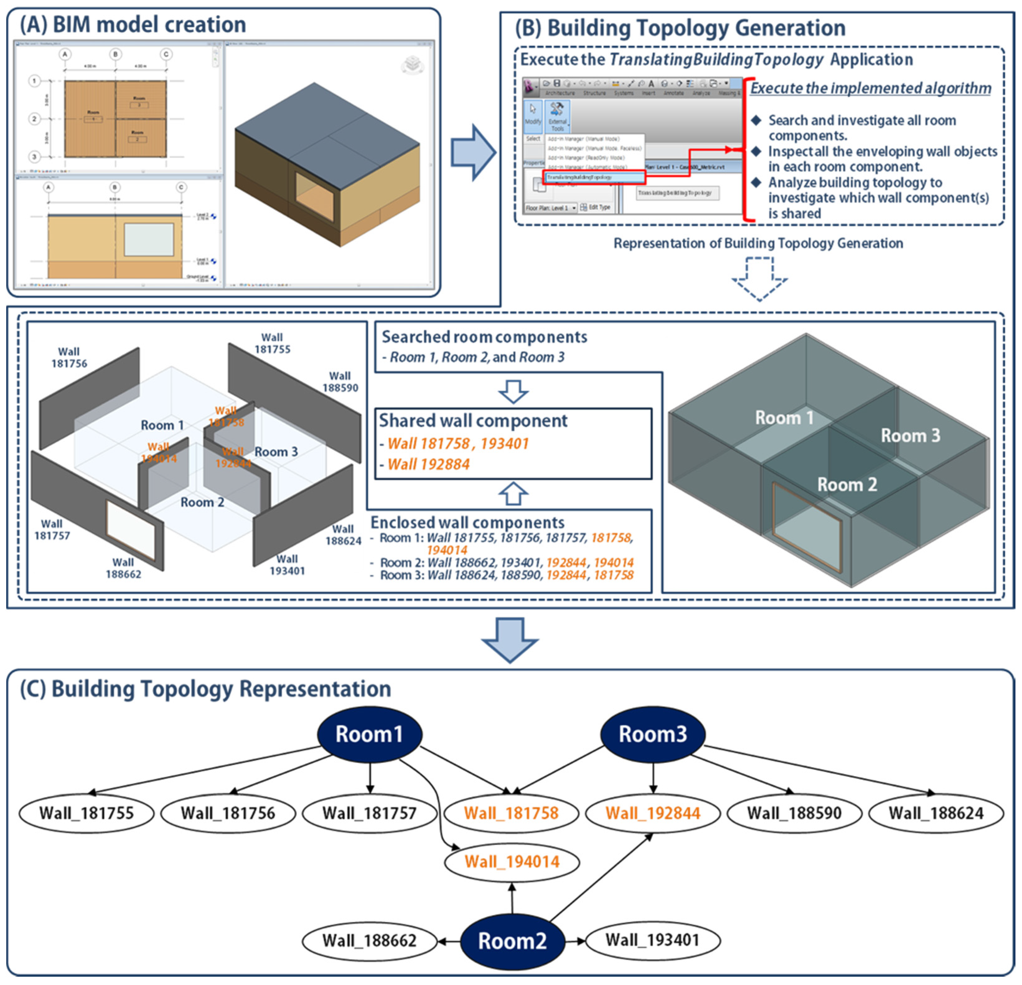
The investigated behavior description allows us to recognize the translation process between BIM and ModelciaBEM. Such an identified translation process can be represented as a set of flow charts consisting of: (1) filtering room objects; (2) retrieving and storing building components; and (3) assigning types of space boundary condition, which explains a data flow for object mapping (Figure 1). Each step of the flow chart can be described as a function description in pseudocodes.
(1)
Filter room objects (in Figure 1A)
The created BIM model contains building components, represented as elements in Revit. Such building components have relationships with each other and follow their own data structure. For example, a room object should be enclosed with building objects and instantiated from the Room class. The Room class has super-subclass relationships with the SpatialElement class, which provides boundary segments in accordance with the building elements enclosing the room object. In order to search and store room objects in a BIM model, we defined a series of processes, including: (1) traversing the created BIM model; (2) collecting all building elements into a variable; (3) retrieving spatial elements from among the building elements; (4) filtering room objects in the spatial elements; and then (5) storing the room objects into a room-arraylist variable.
(2)
Retrieve and store building components (in Figure 1B)
The room-arraylist variable enables the created building components to be categorized in the wall, floor, and roof categories. As shown in the B section in Figure 1, each index in the arraylist allows the filtering of building components in each room object by traversing the room-arraylist variable, using an iterator, until the number of iterations is the same as the size of the room-arraylist variable. Each room object facilitates inspection of the building components categorization due to the relationship with other classes, including the SpatialElementBoundaryOptions and BoundarySegment classes, which provide enveloping wall components. The following pseudocodes description section explains the details of the building components categorization using the related classes.
(3)
Assign space boundary construction types (in Figure 1C)
The arraylists consisting of wall-arraylist, floor-arraylist, and roof-arraylist include room object information and enveloping building components information. For example, a wall-arraylist contains the identification information of a room object in the first index and the walls’ identification information from the second index, sequentially. Therefore, comparison of two wall-arraylists enables the identification of which walls are shared between room objects. If there is the same wall identification information in two wall-arraylists, we can assign one of the walls as an opaque surface on an interior wall (datConBou in the space boundary condition) and the other wall can be the other opaque surface on the same interior wall (surBou in the space boundary condition).
Figure 1. Room-to-Thermal zone translation flow chart describing a data flow corresponding with the identified behavior description. (A) Filter room objects; (B) Retrieve and store building components; (C) Assign space-boundary-condition types.
Energies 09 00050 g001
The developed flow chart diagram (Figure 1) allows us to describe a series of functions through pseudocodes. The following describe pseudocodes section explains the description of the pseudocodes.

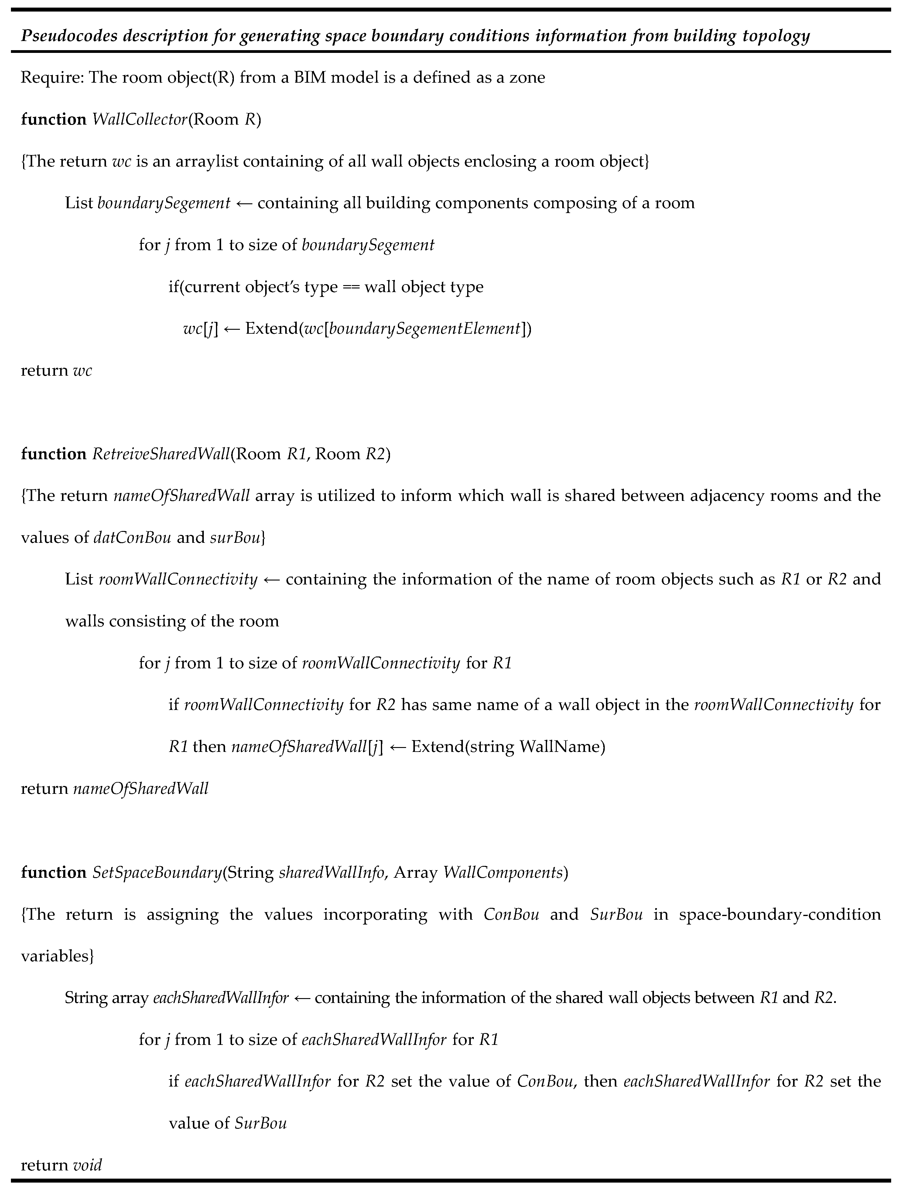
5.2.2. Describe Pseudocodes

The main purpose of the pseudocodes description is to support the implementation of the flow chart as a specific command in the BIM environment. In order to facilitate implementation in a specific BIM authoring tool (Revit), we explored the Revit API, which allows access to the BIM data structure and the retrieval of the created building components information, including geometry and non-geometry information. The predefined classes in the API enable us to describe the flow chart as pseudocodes. For example, we defined the WallCollector function corresponding with the process of retrieving and storing the wall components from a room object in the flow chart (Figure 1B), and utilize the BoundarySegment class to access the enveloping wall components from a room object. The pseudocodes in Figure 2 show the process of assigning space boundary condition types using a room object.
Figure 2. A pseudocode description to match building topology into space boundary conditions.
Energies 09 00050 g002
The defined functions in Figure 2 enable the algorithm to detect shared wall objects between room objects. The functions describe only the investigation process of space boundary condition type from a BIM model. Other required processes defined in the flow chart will be directly implemented using Revit API; we used the FilteredElementCollector class to collect all building elements in a BIM model. The detailed implementation explanation will be discussed in the Implement the Pseudocode Description section.

5.2.3. Implement the Pseudocode Description

We implemented the pseudocodes using the C# language incorporated with Revit API and developed a TranslatingBuildingTopology command. We developed a chain of functions to compose the command as shown in Figure 3, Figure 4 and Figure 5. TranslatingBuildingTopology enables the building topology in a BIM model: (1) to be graphically represented as a connectivity diagram; and (2) to be translated into specific values for space boundary condition variables in a ModelicaBEM model. The following code blocks in the figures demonstrate the room-to-thermal zone translation, focusing on the shared wall information retrieval process.

(1) Room Objects Retrieval Process Implementation

We created an element-collect instance from the Revit API class (FilteredElementCollector class) to retrieve all elements in a Revit BIM model. Then we filtered the collected elements into spatial elements, as shown in Figure 3a. The RoomFilter construction enables the filtered spatial element to sort room objects. Finally, we created an array-list instance to collect room objects from the room filtered element using the RoomFilter construction (Figure 3b).
Figure 3. A code block to describe room objects retrieval process from a Revit BIM model.
Energies 09 00050 g003

(2) Enveloping Wall Retrial Function Implementation

After completing the collection of room objects in an array-list, we can explore the array-list to investigate the enveloping walls of each room object. We conducted the investigation with the WallCollector function implementation shown in Figure 4. The function consists of two declaration parts: (1) enveloping element collector declaration (Figure 4a); and (2) wall object collector declaration (Figure 4b). The envelope element collector declaration part demonstrates the process of collecting boundary elements which enclose a room object. We collected the enveloping elements in an arraylist instance, and then we explored the instance until all the elements are investigated, whether they are wall objects or not. Once an element in the arraylist meets the condition, we stored it in a wall arraylist as a wall object. Figure 4 shows the implementation of the two declarations using provided classes from Revit API; we utilized the SpatialElementBoundaryOptions and BoundarySegment classes to define the declarations.
Figure 4. A code block to describe enveloping wall objects retrieval process in each room object.
Energies 09 00050 g004

(3) Shared Wall Information Retrieval Function Implementation

The shared wall information between rooms supports the defining of the space boundary condition, especially the conditions of both surfaces of the interior wall shared by room objects (named as datConBou and surBou in ModelicaBEM). Once shared wall objects are identified, we can assign the datConBou and surBou conditions based on the object information, including the number of datConBou and surBou. We developed a RetrieveSharedWallInformation function as shown in Figure 5. The implementation is mainly focused on the retrieval of the shared wall’s name. Once the name of the shared wall is identified, we can retrieve other walls’ information, such as area, tilt, and azimuth, by modifying parts of the wall information provided by the Wall class in Revit API. To collect the shared wall’s name, we identified the connectivity between room and wall objects, as shown in Figure 5a. The connectivity represents that the relationships between a room and enveloping walls attached to the room by storing the name of the room and walls into an arraylist. Based on the rooms’ connectivity information, we implemented a comparison of the rooms’ connectivity as shown in Figure 5b. After conducting the comparison, we can acquire the name of the shared wall with the rooms’ names. For example, if a wall whose name is FrontWall is shared with two rooms (named RightRoom and LeftRoom), the function provides a series of string-type values separated by comma and semi-colon such as “FrontWall, RightRoom; FrontWall, LeftRoom”. In addition, the RetrieveSharedWallInformation function enables the connectivity to be visualized through a series of nodes. We will demonstrate the visualization in the following experiments section.
Figure 5. A code block to describe the shared wall information retrieval process between room objects.
Energies 09 00050 g005
The implemented functions enable building topology, represented by the object connectivity in the implementation, to be translated into space boundary condition types such as datConBou and surBou retrieved by the shared wall information. In the experiments section, we will demonstrate the implemented functions by applying them into BIM models, including a validated energy model (BESTEST 600), and providing energy simulation results to validate the translation.

6. Experiments

We conducted: (1) experiments by applying the implemented TranslatingBuildingTopology command to a multi-zone BIM; and (2) simulation result comparisons between two ModeliaBEM models. One model includes the translated space boundary conditions generated from the command and the other is manually created following the OOPM simulation engine specifications (following LBNL Modelica Buildings library and ModelicaBIM library [16]). For the experiments, we conducted three test cases (a one-room model, a two-room model, and a three-room model). These cases are based on a one-room model adopted from the BESTEST Case 600 building: evenly dividing the room in the one-room model to create two rooms, and evenly dividing the right room in the two-room model to create three rooms. We hypothesized that if our algorithm represented the translation, and if the implementation of the flow chart was correct, the ModelicaBEM models of each case could produce close or identical simulation results.

6.1. Test Cases

For the test cases, we created equivalent three BIM models incorporated with Autodesk Revit Architecture: a one-room model (Test Case 1), a two-room model having two windows (Test Case 2), and a three-room model having a window (Test Case 3). Based on the one-room model, the other models were created to present more variation of building topology. The following sections discuss each test case, focusing on: (1) building topology representation focusing on the wall-room connectivity; (2) space boundary condition representation in a ModelicaBEM model; and (3) simulation result comparisons.

6.1.1. Building Topology Representation

(1) Test Case 1: Creating a Basic Building Model

To conduct Test Case 1, we created a one-room building model using Revit Architecture corresponding to the BESTEST Case 600 building model description. The definition of the BESTEST Case 600 model is given in [40,41] and is as follows.
  • One room of a single thermal zone, 8.0 m × 6.0 m × 2.7 m in length, width and height, respectively.
  • The building model consists of four exterior walls, a roof, a floor, and two south-oriented 6 m2 windows, but no doors, as shown in Figure 6a.
  • The building components have building envelope material properties as described in Table 3.
  • No shade and no internal heat gains from occupancy and equipment occur inside the building.
  • The floor is located above ground level and is not attached to the ground.
  • The location of the building is Denver, CO, U.S.
  • The building is lightweight.
Figure 6. Building topology representation process diagram for Test Case 1.
Energies 09 00050 g006
Table 3. Material specification for the BESTEST Case 600 building model adapted from [40,42].
MaterialThickness (m)Thermal Conductivity (W/m·K)Specific Heat Capacity (J/kg·K)Mass Density (kg/m3)
Exterior Wall (Inside to Outside)
Plasterboard0.0120.160840950
Fiberglass quilt0.0660.04084012
Wood siding0.0090.140900530
Floor (Inside to Outside)
Timber flooring0.0250.1401200650
Insulation1.0030.04000
Roof (Inside to Outside)
Plasterboard0.0100.160840950
Fiberglass quit0.11180.04084012
Wood siding0.0190.140900530
We created a BIM model based on the description shown in Figure 6a. The BIM model contains the material information shown in Table 3 by adopting the adding material command from [15]. The BIM model consists of four wall objects, a roof object, and a floor object. The south-facing wall object has two 6 m2 windows. The room object is enclosed by the building objects and the room has no interior wall object.
The TranslatingBuildingTopology command translates the room object in the BIM model into the building topology representation. Figure 6 shows the translation (Figure 6b) and the building topology representation (Figure 6c).
We adopted the Microsoft automatic graph layout (MSAGL) tool [43] to implement the graphical representation of the building topology. The WallCollector and RetrieveSharedWallInformation functions enable the TranslatingBuildingTopology command to retrieve the wall object information attached to the room object shown in Figure 6b and Figure 6c. The command collects the wall’s identification number from a wall object in the BIM model and then generates a new wall’s name by combining the wall-id number with the predefined identification word (Wall_), e.g., Wall_194276. Each new wall’s name is represented in an oval shape node and is connected into a room node with an arrow (Figure 6c).

(2) Test Case 2: Creating a Two-Room Building from the One-Room Building

We modified the one-room building model by installing an interior wall to evenly divide the single zone into a two-thermal zone, removing the left window object in the south-facing wall of the one-room model, and installing an east-facing 6 m2 window as in Figure 7a.
After the command explored all the wall objects enveloping the two room objects, it retrieved all walls’ id numbers (Figure 7b). The walls’ id numbers enable the command to demonstrate which wall object is shared between the rooms, using the comparison function in the TranslatingBuildingTopology command. Test Case 2 shows that the installed interior wall is the shared wall object (Wall_181758) through node connectivity representation, which means that the behavior of adding an interior wall is correctly translated into the behavior of retrieving a shared wall object having two surfaces between two thermal zones.
Figure 7. Building topology representation process diagram for Test Case 2.
Energies 09 00050 g007

(3) Test Case 3: Creating a Three-Room Building from the Two-Thermal-Zone Building

To demonstrate a more diverse building topology translation, we installed another interior wall in the right room object of Test Case 2 (Figure 8a). The updated BIM model has three rooms; the west room has the same dimension as in Test Case 2, but the east room in Test Case 2 is divided into a south room and a north room. The south and north room measure 4.0 m × 3.0 m × 2.7 m in length, width, and height, respectively. In adding another interior wall to create south and north rooms, we removed the east-facing window. Note that we referred to the west room, the south room and the north room as Rooms 1–3 respectively, as shown in Figure 8b. The only difference between Room 1 and Room 3 is the size. We will demonstrate how the difference can affect the simulation result in the following simulation result comparisons section.
The TranslatingBuildingTopology command shows the wall-room connectivity based on the shared wall-id numbers retrieval process (Figure 8c). The connectivity diagram implies that the heat transfer is conducted through Wall_194014 between Rooms 1 and 2, through Wall_181758 between Rooms 1 and 3, and through Wall_192844 between Rooms 2 and 3.
Figure 8. Building topology representation process diagram for Test Case 3.
Energies 09 00050 g008

6.1.2. Space Boundary Condition Representation in a ModelicaBEM Model

To represent the space boundary condition by following the object-oriented concept and the architecture viewpoint instead of an engineer’s, we adopted the LBNL Modelica Buildings library (as an OOPM simulation engine) and ModelicaBIM library (to wrapper the simulation engine as the architecture viewpoint) [16]. The specification of the two libraries enables the created building topology to be represented as instances in a ModelicaBEM model.

(1) Test Case 1: Single-Thermal-Zone ModelicaBEM Model

Once the building topology representation is executed, the TranslatingBuildingTopology command generates the values of the space boundary conditions. As shown in Figure 9, the room has three exterior walls (translated into the number of datConExt), excepting the exterior wall with windows (translated into the number of datConExtWin). The Room 1 object is translated into the ThermalZone object in a ModelicaBEM model. The ThermalZone object includes two space boundary condition types (datConExt and datConExtWin) and the values of the types are translated from the wall-room connectivity in the building topology. The number of the datConExt in the ModelicaBEM model can be five (Figure 9A) due to the calculation of the total number of opaque surfaces in the room model corresponding with the surfaces of three exterior walls, the floor, and the roof object. The variables in datConExt (Figure 9A) and datConExtWin (Figure 9B), such as layers, area (A), tilt (til), and azimuth (azi), have the values from the instantiated building component objects, such as Wall_194276.structure in the layers variable. The wall-room connectivity enables the instantiation to be conducted by following the specification in the ModelicaBIM library.
Figure 9. Space boundary condition representation of the one-thermal-zone ModelicaBEM model.
Energies 09 00050 g009

(2) Test Case 2: Two Thermal Zones ModelicaBEM Model

The main modification between the single thermal zone model and the two thermal zones model is whether the conduction heat transfer is performed through the interior wall’s surface where the interior wall is shared by the two zones. Figure 10 represents the differentiation by identifying the translation of the interior wall object into the datConBou and surBou variables.
Figure 10. Space boundary condition representation of the two-thermal-zones ModelicaBEM model.
Energies 09 00050 g010
The LBNL library defines two construction types: opaque surfaces on interior walls between thermal zones as datConBou and the other opaque surfaces on the same interior walls between the thermal zones as surBou. The Wall_181758 interior wall is identified as the shared interior wall by the TranslatingBuildingTopology command. Therefore, we can identify one surface of the wall as the datConBou type and the opposite surface as the surBou. We implemented the room-filter process in the flow chart as following the room number sequence, and assigned the datConBou type to the surface attaching to the first room object. Therefore, we can assign the datConBou type to the surface oriented into the Room 1 object and the surBou type into Room 2, as shown in Figure 10C. The Room 2 object has two exterior walls with windows, the same as in Test Case 1; therefore, the datConExt and the datConExtWin types can follow same process as for Room 1 in Test Case 1 (Figure 10A,B).

(3) Test Case 3: Three Thermal Zones ModelicaBEM Model

In order to demonstrate the variable building topology translation, we expanded the model with two thermal zones by installing one more interior wall (the interior Wall_192844 object in Figure 11) to split Room 2 as two thermal zones.
Figure 11. Space boundary condition representation of the three-thermal-zones ModelicaBEM model.
Energies 09 00050 g011
The installation of the interior wall between Rooms 2 and 3 enables the interior surface of the Wall_192844 object oriented into Room 2 to be assigned as datConBou (Figure 11C) and the surface of the interior wall oriented into Room 3 as surBou based on our implementation. The interior wall between Rooms 1 and 2 identified as the same condition in Test Case 2; therefore, the surBou construction type can be assigned into the interior surface of the Wall_194014 object oriented into Room 2 (Figure 11D).
The three test cases verify our algorithm development and its implementation by representing: (1) the building topology as building object connectivity; and (2) the translation of the connectivity into the space boundary condition types in each ModelicaBEM model.

6.1.3. Simulation Result Comparisons

We performed thermal simulation from the created ModelicaBEM models using a Dymola 2012 simulation program as a Modelica development environment, LBNL Modelica Buildings library version 1.3 as a simulation solver, and a simulation interval of 3600 s for a one-year period.
In order to validate our approach, we utilized the same BESTEST Case 600 building from Test Case 1 because the simulation results from the LBNL library for the BESTEST Case 600 have been validated [37]. Note that the LBNL’s building model is created by manually writing the building description code, following the specification from the library, while our algorithm’s ModelicaBEM model is created by including the automatically-translated building topology data in the ModelciaBEM model. We apply the coherent model conditions (described in the previous building topology representation section) to all the building models except the building location: Denver, Colorado for Test Case 1 and Chicago, Illinois for Test Cases 2 and 3. The building dimensions of all the test cases are the same, but room dimensions differ based on the test cases’ description, incorporating the split of thermal zones. We created two ModelicaBEM models for all the test cases, the algorithm’s version and LBNL’s version, to demonstrate an annual indoor air temperature change without an HVAC system module.
In summary, the simulation results of all the test case models created by using the developed algorithm (algorithm version) agree with the results from the model created with the LBNL Modelica Buildings library (LBNL version). Two models of each test case show almost identical (Test Case 1) or close (Test Cases 2 and 3) simulation results of annual indoor air temperature of all three test cases. In Table 4, the dates when the highest and lowest temperatures are found in each room of the algorithm version model are the same as the dates in the LBNL version model. For example, in Test Case 1, as shown in Table 4, the highest temperature occurred at 3:00 p.m. on 17 October and the lowest temperature at 7:00 a.m. on 4 January in both ModelicaBEM models.
Overall, the ModelicaBEM models including the translated building topology data produce very similar simulation results to LBNL’s models. This is expected because we applied the same thermal simulation algorithm from the LBNL Modelica Buildings library to all the ModelicaBEM models.
However, two major differences exist between the ModelicaBEM models: the modeling approach and the model structures. The simulation result comparison experiments can have unpredictable simulation results due to the differences if the algorithm is not developed or implemented correctly.
Regarding the modeling approach, our implemented algorithm allows a more comprehensive energy model creation to reflect the actual building semantics. In the examples of Test Cases 2 and 3, the LBNL’s model represents the interior wall object as different surface objects to follow energy semantics, e.g., boundary condition. However, our approach automatically recognizes both surfaces from the interior wall object and identifies the orientation of each surface to represent the actual building configuration, e.g., building component connectivity: one is for a room object and the other is for the other room object.
Regarding the model structure, the ModelicaBEM models, by applying our algorithm implementation, use architecture semantics, such as rooms instead of engineering-based semantics, such as MixedAir objects. To demonstrate the architectural modeling structure, we adopted the ModelicaBIM library, allowing wrapping the MixedAir class in LBNL Modelica Buildings library as the Room class in the ModelicaBIM library.
Table 4. Annual peak temperatures of the Test Cases.
Test CaseRoom NameHighest Temperature (°C)/Date, TimeLowest Temperature (°C)/Date, Time
1Room 1Algorithm version: 65.7 °C/17 October, 3:00 p.m.Algorithm version: −19.8 °C/4 January, 7:00 a.m.
LBNL version: 65.9 °C/17 October, 3:00 p.m.LBNL version: −19.8 °C/4 January, 7:00 a.m.
2Room 1Algorithm version: 34.9 °C/19 July, 9:00 p.m.Algorithm version: −12.3 °C/8 January, 11:00 a.m.
LBNL version: 35.4 °C/19 July, 9:00 p.m.LBNL version: −12.2 °C/8 January, 11:00 a.m.
Room 2Algorithm version: 42.2 °C/18 July, 10:00 a.m.Algorithm version: −13.2 °C/8 January, 7:00 a.m.
LBNL version: 43.6 °C/18 July, 10:00 a.m.LBNL version: −13.2 °C/8 January, 7:00 a.m.
3Room 1Algorithm version: 34.2 °C/19 July, 9:00 p.m.Algorithm version: −12.5 °C/8 January, 11:00 a.m.
LBNL version: 34.6 °C/19 July, 9:00 p.m.LBNL version: −12.5 °C/8 January, 11:00 a.m.
Room 2Algorithm version: 40.8 °C/18 July, 1:00 p.m.Algorithm version: −10.5 °C/31 January, 2:00 a.m.
LBNL version: 41.7 °C/18 July, 1:00 p.m.LBNL version: −10.5 °C/31 January, 2:00 a.m.
Room 3Algorithm version: 34.0 °C/19 July, 9:00 p.m.Algorithm version: −11.2 °C/8 January, 11:00 a.m.
LBNL version: 34.4 °C/19 July, 9:00 p.m.LBNL version: −11.2 °C/8 January, 11:00 a.m.

7. Conclusions and Future Work

This paper presents a new translation algorithm integrating BIM and Modelica-based OOPM for building thermal simulation. The implemented command from the algorithm enables inter-disciplinary data exchange between the two object-oriented models (BIM models and ModelicaBEM models). The algorithm can leverage the consistent use of the original building data including building topology in the energy simulation without manually rewriting them in energy models. The building data in BIM already created by architects or designers can significantly eliminate the overhead in identifying the required building description data for input data in building energy modeling. The suggested algorithm and implementation in this paper have the capability to improve error-prone manual energy modeling processes.
Our algorithm and its implementation utilized BIM API instead of the standard data schemas, such as IFC and gbXML, for natural mapping processes. We acknowledge the benefits of adopting the standard schemas to enhance interoperability for model translation among various BIM tools and energy simulation tools. However, the use of BIM API enables direct access to BIM data in developing specific commands and preserves parametric modeling capability. We will expand the feasibility of the algorithm by applying it to other BIM tools to enhance the interoperability.
Our suggested algorithm facilitates the development of a system interface, enabling multi-zone BIM models to be automatically translated into ModelicaBEM models with high efficiency and accuracy. The advance of the algorithm is to enhance the efficiency of natural mapping between two object-oriented models, which can facilitate efficient model translation from object-based design models to diverse building performance simulation. We will expand our algorithm and the implementation of it to cover more complicated building models, including the vertical stacking of rooms and the addition of doors. Additionally, a future project will investigate the use of standard schemas such as IFC for building topology translation into OOPM-BEM. Moreover, the current version is focused on thermal simulation; we will expand the coverage of the algorithm into more simulation domains, including daylight and photovoltaics.

Acknowledgments

The authors are grateful to Wei Yan at Texas A & M University for valuable advises and contribution to this research. This research was supported by Basic Science Research Program through the National Research Foundation of Korea (NRF) funded by the Ministry of Science, ICT (Information and Communication Technology) and Future Planning (No. NRF-2013R1A1A1010562 and No. NRF-2013R1A2A2A04014772).

Author Contributions

All authors read and approved the manuscript. All authors contributed to this research work, discussed the results and implications and involved in the manuscript development at all stages. WoonSeong Jeong provided precious ideas on the establishment of algorithm and its implementation as well as experiments. JeongWook Son discussed the main idea to develop this research work and reviewed and revised the manuscript as well as led the development of the paper.

Conflicts of Interest

The authors declare no conflict of interest.

References

  1. Bazjanac, V. IFC BIM-Based Methodology for Semi-Automated Building Energy Performance Simulation; Lawrence Berkeley National Lab.: Berkeley, CA, USA, 2008. [Google Scholar]
  2. Bazjanac, V. Implementation of semi-automated energy performance simulation: Building geometry. In Proceedings of the CIB, Istanbul, Turkey, 8–11 October 2009; pp. 595–602.
  3. Hand, J.W.; Crawley, D.B.; Donn, M.; Lawrie, L.K. Improving the data available to simulation programs. In Proceedings of the Building Simulation, Montréal, QC, Canada, 7–9 August 2005; pp. 373–380.
  4. Bazjanac, V.; Maile, T.; Rose, C.; O’Donnell, J.T.; Mrazović, N.; Morrissey, E.; Welle, B.R. An assessment of the use of building energy performance simulation in early design. In Proceedings of the Building Simulation, Sydney, Australia, 14–16 November 2011; pp. 1579–1585.
  5. Hitchcock, R.J.; Wong, J. Transforming IFC architectural view BIMs for energy simulation: 2011. In Proceedings of the Building Simulation, Sydney, Australia, 14–16 November 2011; pp. 1089–1095.
  6. U.S. Department of Energy (U.S. DOE). Best Directory|Building Energy Software Tools. Available online: http://www.buildingenergysoftwaretools.com (accessed on 4 August 2015).
  7. Clarke, J. Energy Simulation in Building Design, 2nd ed.; Routledge: London, UK, 2001. [Google Scholar]
  8. Crawley, D.B.; Hand, J.W.; Kummert, M.; Griffith, B.T. Contrasting the capabilities of building energy performance simulation programs. Build. Environ. 2008, 43, 661–673. [Google Scholar] [CrossRef] [Green Version]
  9. Maile, T.; Fischer, M.; Bazjanac, V. Building Energy Performance Simulation Tools—A Life-Cycle and Interoperable Perspective; Center for Integrated Facility Engineering (CIFE) Working Paper 107; Lawrence Berkely National Lab.: Berkeley, CA, USA, 2007; pp. 1–49. [Google Scholar]
  10. Attia, S. State of the Art of Existing Early Design Simulation Tools for Net Zero Energy Buildings: A Comparison of Ten Tools; Université Catholique de Louvain: Louvain La Neuve, Belgium, 2011. [Google Scholar]
  11. Aksamija, A. BIM-based building performance analysis: Evaluation and simulation of design decisions. In Proceedings of the 2012 ACEEE Summer Study on Energy Efficiency in Buildings, Pacific Grove, CA, USA, 12–17 August 2012.
  12. General Services Administration. 3D-4D Building Information Modeling. Available online: http://www.gsa.gov/portal/content/105075?utm_source=PBS&utm_medium=print-radio&utm_term=bim&utm_campaign=shortcuts (accessed on 4 August 2015).
  13. Rose, C.M.; Bazjanac, V. An algorithm to generate space boundaries for building energy simulation. Eng. Comput. 2013, 31, 271–280. [Google Scholar] [CrossRef]
  14. Jeong, W.; Kim, J.B.; Clayton, M.J.; Haberl, J.S.; Yan, W. Translating building information modeling to building energy modeling using Model View Definition. Sci. World J. 2014, 2014, 1–21. [Google Scholar] [CrossRef] [PubMed]
  15. Jeong, W.; Kim, J.B.; Clayton, M.J.; Haberl, J.S.; Yan, W. A framework to integrate object-oriented physical modelling with building information modelling for building thermal simulation. J. Build. Perform. Simul. 2015. [Google Scholar] [CrossRef]
  16. Kim, J.B.; Jeong, W.; Clayton, M.J.; Haberl, J.S.; Yan, W. Developing a physical BIM library for building thermal energy simulation. Autom. Constr. 2015, 50, 16–28. [Google Scholar] [CrossRef]
  17. Yan, W.; Clayton, M.; Haberl, J.; Jeong, W.; Kim, J.; Kota, S.; Bermudez Alcocer, J.; Dixit, M. Interfacing BIM with building thermal and daylighting modeling. In Proceedings of the 13th International Conference of the International Building Performance Simulation Association, Chambery, France, 26–28 August 2013; pp. 3521–3528.
  18. Bazjanac, V.; Maile, T. IFC HVAC Interface to EnergyPlus—A Case of Expanded Interoperability for Energy Simulation; Lawrence Berkeley Natl. Lab: Berkeley, CA, USA, 2004. [Google Scholar]
  19. O’Donnell, J.; See, R.; Rose, C.; Maile, T.; Bazjanac, V.; Haves, P. SimModel: A domain data model for whole building energy simulation. In Proceedings of the Building Simulation, Sydney, Australia, 14–16 November 2011; pp. 382–398.
  20. Bazjanac, V. Space boundary requirements for modeling of building geometry for energy and other performance simulation. In Proceedings of the CIB W78: 27th International Conference, Cairo, Egypt, 16–18 November 2010.
  21. Bazjanac, V.; Kiviniemi, A. Reduction, simplification, translation and interpretation in the exchange of model data. In Proceedings of the 24th W78 Conference Maribor 2007, Maribor, Slovenia, 26–29 June 2007; pp. 163–168.
  22. Wetter, M.; Zuo, W.; Nouidui, T.S.; Pang, X. Modelica buildings library. J. Build. Perform. Simul. 2014, 7, 253–270. [Google Scholar] [CrossRef]
  23. Revit Architecture–Building Design Software—Autodesk. Available online: http://www.autodesk.com/products/revit-family/overview (accessed on 15 January 2016).
  24. About ArchiCAD—A 3D CAD Software for Architectural Design & Modeling. Available online: http://www.graphisoft.com/products/archicad (accessed on 15 January 2016).
  25. Bentley System. Building Information Modeling—Bentley Architecture. Available online: https://www.bentley.com/en/products/brands/aecosim (accessed on 15 January 2016).
  26. Eastman, C.M.; Teicholz, P.; Sacks, R.; Liston, K. BIM Handbook: A Guide to Building Information Modeling for Owners, Managers, Designers, Engineers and Contractors; John Wiley and Sons: Hoboken, NJ, USA, 2008. [Google Scholar]
  27. Lee, G.; Sacks, R.; Eastman, C.M. Specifying parametric building object behavior (BOB) for a building information modeling system. Autom. Constr. 2006, 15, 758–776. [Google Scholar] [CrossRef]
  28. Autodesk Developer Center—Autodesk® Revit® Architecture, Autodesk® Revit® Structure and Autodesk® Revit® MEP. Available online: http://usa.autodesk.com/adsk/servlet/index?siteID=123112&id=2484975 (accessed on 4 August 2015).
  29. GRAPHISOFT. Graphisoft Developer Center. Available online: http://www.graphisoft.com/support/developer (accessed on 4 August 2015).
  30. Fritzson, P. Principles of Object-Oriented Modeling and Simulation with Modelica 2.1; John Wiley and Sons: Hoboken, NJ, USA, 2010. [Google Scholar]
  31. Tiller, M. Introduction to Physical Modeling with Modelica; Kluwer Academic Publishers: Boston, MA, USA, 2001. [Google Scholar]
  32. Wetter, M. Modelica-based modeling and simulation to support research and development in building energy and control systems. J. Build. Perform. Simul. 2009, 2, 143–161. [Google Scholar] [CrossRef]
  33. Tummescheit, H. Design and Implementation of Object-Oriented Model Libraries Using MODELICA; Lund University: Lund, Sweden, 2002. [Google Scholar]
  34. Fritzson, P.; Bunus, P. Modelica—A general object-oriented language for continuous and discrete-event system modeling and simulation. In Proceedings of the 35th Annual Symposium, San Diego, CA, USA, 14–18 April 2002; pp. 365–380.
  35. Wetter, M. Modelica Library for Building Energy and Control Systems. Available online: https://simulationresearch.lbl.gov/modelica (accessed on 4 August 2015).
  36. Wetter, M.; Zuo, W.; Nouidui, T.S. Modeling of heat transfer in rooms in the MODELICA “Buildings” library. In Proceedings of the Building Simulation, Sydney, Australia, 14 November 2011; pp. 1096–1103.
  37. Nouidui, T.S.; Phalak, K.; Zuo, W.; Wetter, M. Validation and application of the room model of the Modelica buildings library. In Proceedings of the 9th International Modelica Conference, Munich, Germany, 3–5 September 2012; pp. 727–736.
  38. Energy in Building and Communities Programme. IEA EBC Annex 60. Available online: http://www.iea-annex60.org (accessed on 23 November 2015).
  39. Wetter, M. Multizone airflow model in Modelica. In Proceedings of the 5th International Modelica Conference, Vienna, Austria, 4–5 September 2006; pp. 431–440.
  40. Judkoff, R.; Neymark, J. International Energy Agency Building Energy Simulation Test (BESTEST) and Diagnostic Method; National Renewable Energy Lab.: Golden, CO, USA, 1995. [Google Scholar]
  41. Pedersen, C.O.; Liesen, R.J.; Strand, R.K.; Fisher, D.E. A Toolkit for Building Load Calculations; American Society of Heating, Refrigerating and Air-Conditioning Engineers Inc.: Oklahoma City, OK, USA, 2001. [Google Scholar]
  42. ASHRAE. ANSI/ASHRAE Standard 140-2007 Standard Method of Test for the Evaluation of Building Energy Analysis Computer Programs; America Society of Heating, Refrigerating and Air-Conditioning Engineers Inc.: Atlanta, GA, USA, 2010. [Google Scholar]
  43. Microsoft Corporation. Microsoft Automatic Graph Layout—Microsoft Research. Available online: http://research.microsoft.com/en-us/projects/msagl (accessed on 4 August 2015).

