Article

Basic Characteristics and Design of a Novel Hybrid Magnetic Bearing for Wind Turbines

School of Electrical and Information Engineering, Jiangsu University, Zhenjiang 212013, China
*
Author to whom correspondence should be addressed.
Energies 2016, 9(11), 905; https://doi.org/10.3390/en9110905
Submission received: 8 September 2016 / Revised: 20 October 2016 / Accepted: 20 October 2016 / Published: 2 November 2016

Abstract

:
This paper proposes a five-degree-of-freedom (5-DOF) hybrid magnetic bearing (HMB) for direct-drive wind turbines, which can realize suspension in the 4-DOF radial and 1-DOF axial directions. Only two sets of radial control windings are employed in the proposed HMB because only one set of radial control windings can achieve the 2-DOF suspension in the radial direction. Unlike the traditional active thrust magnetic bearings, this paper uses a cylindrical rotor core without a large thrust disc in the novel HMB. The numbers of the controller, power amplifier and system volume can be reduced in the magnetic suspension system. This paper also presents the structure and basic characteristics of the proposed magnetic bearing. A precision equivalent magnetic circuit analysis of the permanent magnet ring and control magnetic field is conducted in this study, in consideration of the non-uniform distribution of magnetic density. Accordingly, the mathematical models, including the suspension force expression, are derived based on the accurate equivalent magnetic circuit. The basic principle of the structure parameter design is presented, based on the given key parameters. The accuracy of the analytical method is further validated by 3D finite element analysis.

1. Introduction

Wind turbines have received extensive attention from all over the world because wind energy is a clean and renewable energy. Because the gear boxes are the key factors of maintenance in the wind power generation systems, so the direct-drive permanent magnet wind power generators with no gear boxes are replacing the traditional wind power generators by the wind power manufactures [1,2]. The traditional direct-drive wind turbines supported by ball bearings have a high wind speed at starting, serious wear and mechanical friction problems, and the utilization rate is really low because of aerodynamics (Betz limit) beyond friction and its consequences. Magnetic bearings have a potential application in wind turbines, because of their advantages, including no friction, no wear, no oil lubrication, no seals, low cost, low loss and long life, among others [3,4,5,6,7,8].
The wind turbines supported by magnetic bearings have many advantages, which include the following: (a) the utilization rate of wind energy will be improved and the threshold wind speed will be reduced because no contact and friction between the stator and the rotor will occur; (b) the costs, environmental pollution and loss will be reduced because no lubrication is present in the magnetic bearings; and (c) magnetic bearings have high adaptability to extreme climate conditions [9,10,11,12].
The magnetic bearings used in wind turbines can be classified into three types as follows: active, passive and hybrid magnetic bearings [13,14,15,16]. The active magnetic bearings (AMBs) have suspension forces for the rotor that are generated by the coil currents. The AMBs have high control precision and great bearing capacity. However, the AMB systems are composed of sensors, power electronics and controllers. The passive magnetic bearings (PMBs) can stabilize the rotor with some degrees of freedom without active control. However, the stability and controllable properties of the PMBs are poor. Hybrid-type magnetic bearings have been proposed to combine the merits of AMBs and PMBs. These bearings are thought to be a valuable bearing type. Accordingly, many kinds of hybrid-type magnetic bearings are used in wind turbines and industrial applications [17,18].
The current magnetic suspension system, which mainly adopts one degree-of-freedom (DOF) in the axial direction and 4-DOF in the radial direction, can achieve the suspension in the 5-DOF. This kind of system is widely employed in many industries, such as in precision machining, aeronautics and astronautics [19,20]. Two 2-DOF magnetic bearings are concurrently controlled to achieve 4-DOF in the radial direction. A 2-DOF magnetic bearing usually needs at least four sets of controllers and power amplifiers. The magnetic suspension system with 4-DOF in the radial direction needs at least eight sets of controllers and power amplifiers. Therefore, the magnetic levitation system has a slightly more complicated structure and a higher power consumption [21]. In addition, the axial length of the rotor will be increased when two 2-DOF magnetic bearings are placed alongside the rotor, thereby leading to a system volume and disturbance increase. The stability and controllability of the upper mentioned system will be more difficult. Meanwhile, the magnetic suspension system with the magnetic bearing uses the thrust disc to achieve the suspension in the axial direction at the present stage. Assembling and disassembling are difficult for this system, because the thrust disc is sandwiched between the stators of the magnetic bearing. Moreover, the thrust disc makes the direct insertion of the rotor shaft into the system difficult. Obtaining the dynamic balance of the rotor shaft before the assembly is also hard. In addition, the rotational speed of the thrust disc is limited [22].
Some kinds of 5-DOF magnetic bearings were proposed by many researchers. A 5-DOF magnetic bearing with symmetric permanent magnets and radial stators at the end of the axial thrust disc on the basis of a 2-DOF magnetic bearing was proposed in [23]. Masuzawa T proposed a 5-DOF magnetic bearing system in the 9th International Symposium on magnetic bearings. The axial and radial control fluxes were provided by the radial control windings, but the control fluxes in the radial and axial direction were coupled. The work in [24,25] proposed a 5-DOF axial force tilting permanent magnet biased magnetic bearing with a split stator.
Accordingly, a novel 5-DOF hybrid magnet bearing (HMB) is proposed in this paper. The 5-DOF HMB can realize the suspension in the 4-DOF radial and 1-DOF axial directions. Only two sets of radial control windings are used in the proposed HMB because a single set of radial control windings can achieve the 2-DOF suspension in the radial direction. The system volume, numbers of controller and power amplifier will then be reduced in the magnetic levitation system. The rotor shaft employing the proposed HMB has a simple columnar shape without a large convexity. As a result, the problems caused by the large thrust disc are resolved. This paper also introduces the basic characteristics of the proposed HMB, then deduces the accurate equivalent magnetic circuit, designs the structure parameters and verifies by a computational check the model of the proposed HMB with the 3D finite element analysis (FEA).

2. Configuration and Operation Principle

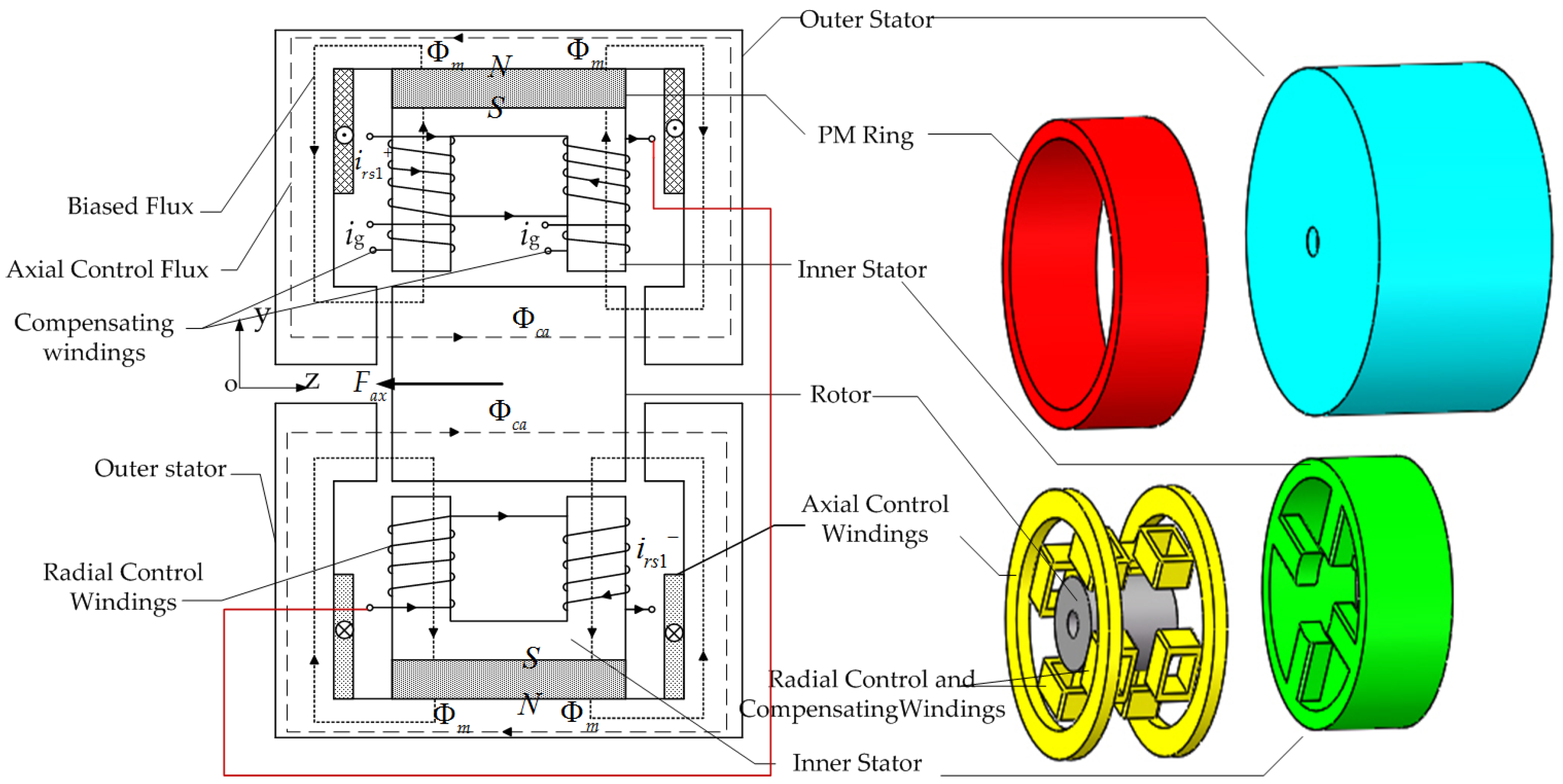
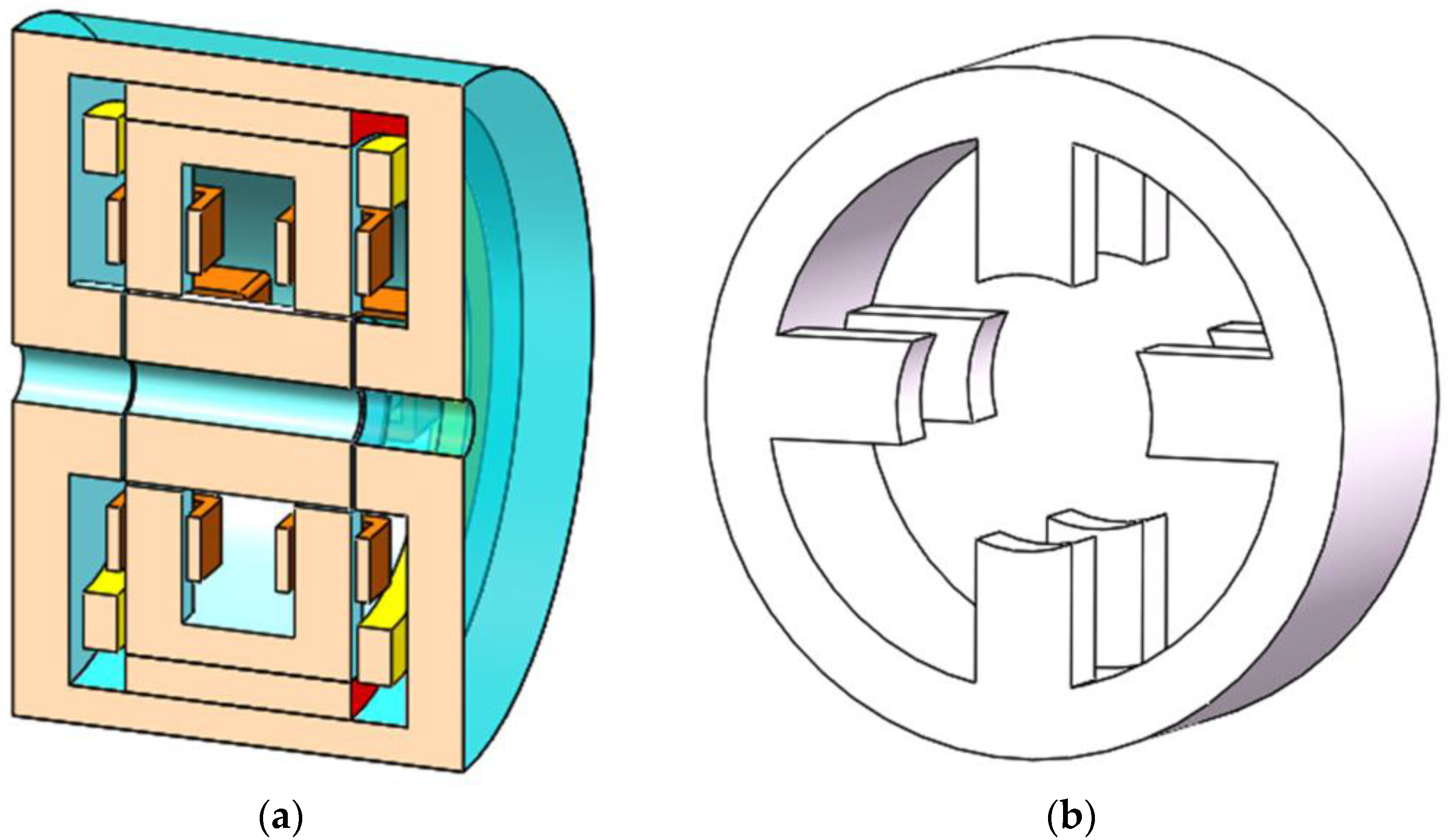
2.1. Structure of the 5-DOF HMB

Figure 1 shows the structure and the exploded view of the new type of 5-DOF HMB. The HMB comprises the outer stator core, inner stator core, cylindrical rotor core, shaft, radial magnetized permanent magnet (PM) ring, eight radial control windings, two sets of compensating windings for eliminating the influence of gravity and two axial control windings. Figure 2a shows the cutaway view of the proposed 5-DOF HMB. The PM ring provides the biased fluxes for the HMB. The static suspension force generated by the PM ring will suspend the rotor in a balanced position.
Figure 2b shows the inner stator core made of a cog structure, in which four pairs of inner stator teeth are uniform along the circumference. Two sets of radial control windings are wound on the inner stator teeth. The two axisymmetric radial control windings are connected in series, as shown in Figure 1. The two sets of the radial windings can control the rotor suspension in 4-DOF. The axial control windings distributed around the rotor are wound between the inner stator core and the outer stator core, to achieve a 1-DOF suspension in the axial direction.
Overall, the proposed 5-DOF HMB can simplify the structure and lower the volume compared to the traditional 5-DOF magnetic bearings. Moreover, the novel 5-DOF HMB uses the cylindrical rotor core without the thrust disc in the axial direction. Then, the rotor in this study is further lightened.

2.2. Principle of Radial Suspension Force Generation

The rotor is assumed to be twisted away from the equilibrium position by a disturbance force in the radial direction (Figure 3). The left air gap in the upper rotor lengthens, whereas the right air gap shortens. Consequently, the left air gap in the lower the rotor shortens, whereas the right air gap lengthens. The current irs1+ is fed into the radial control windings to return to the balance and generate the control flux according to the control demand, as shown in Figure 3. Thus, the control flux will be superposed to the PM-biased flux, which leads to the flux density reduction and increase in the right and left air gaps in the upper rotor. The flux density reduction and increase in the left and right air gaps are also observed in the lower rotor. As a result, the suspension force Fra can lead the rotor to the equilibrium position based on the electromagnetic theory of Maxwell. The principle of the radial suspension force generation in the other two radial DOF is the same as the upper-part.

2.3. Principle of Axial Suspension Force Generation

Figure 1 shows that the rotor will be displaced from the balance position right when a disturbance force is exerted on the rotor in the axial direction. This action results in the length variation of the air gaps in the axial direction. Consequently, the magnitude of the magnetic flux density in the left air gap around the rotor will be smaller than that in the right. The appropriate currents are fed into axial control windings to return the rotor back to the equilibrium position in the axial direction and generate the control flux Φca shown in Figure 1. Thus, the control flux Φca can be superposed with the PM-biased flux Φm, which leads to the increase of the magnitudes of the magnetic flux density and reduction in the left and right air gaps. The rotor will then be pulled back to the equilibrium position in the axial direction based on the electromagnetic theory of Maxwell.
Therefore, the proposed 5-DOF HMB using the PM-biased flux in this study can achieve the stable suspension of the rotor in 5-DOF.

2.4. Principle of Gravity Compensation

The gravity compensation is necessary due to the gravity of the rotor. Traditionally, there are some ways to compensate the gravity of the rotor, such as by using the asymmetric bias flux; by using additional passive control windings, etc. Two sets of compensating windings are used in this HMB. As shown in Figure 1, in order to compensate the gravity of rotor, the smaller constant direct current ig is connected to the two sets compensating windings when the suspension control was acted. Because the gravity of the rotor is much smaller than the external loading, so the compensating current is much smaller than the radial control current. The influence of compensating current on the HBM flux can be ignored in order to simplify the following analysis.

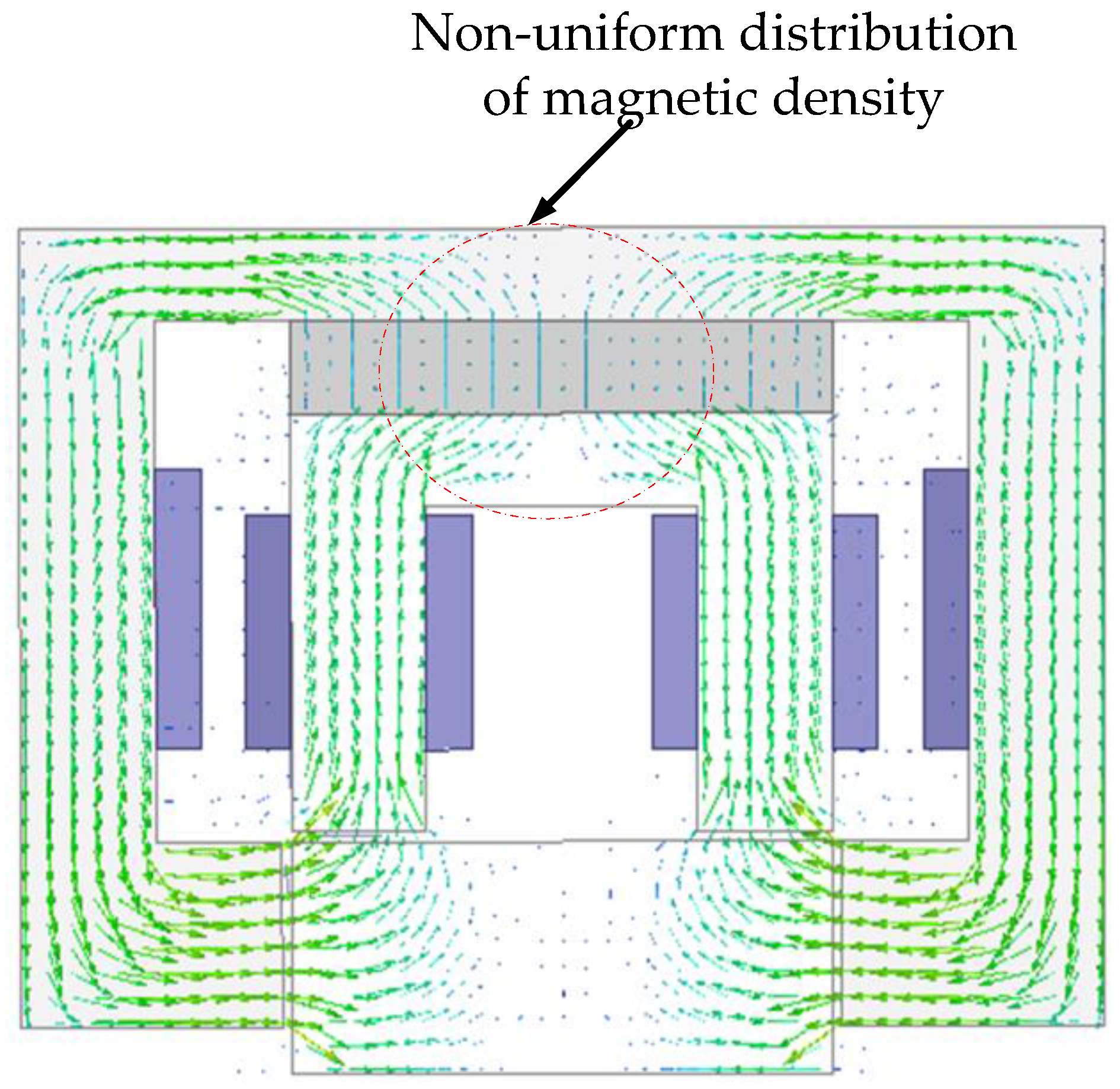
3. Accurate Magnetic Circuit Analysis

Some of the following assumptions are made to simplify the magnetic circulation:
(1)
The reluctance of the stator iron core and of rotor core is not considered.
(2)
Finite coercivities and magnetic saturation are ignored.
(3)
The influence of the compensating current is ignored.

3.1. Accurate Analysis of Equivalent Magnetic Circuit of the PM Ring

The equivalent magnetic circuit will be presented given the flux distribution indicated in Figure 1 and Ohm’s law for the equivalent magnetic circuit. The equivalent circuit model of the proposed 5-DOF HMB is shown in Figure 4, because of the symmetry of the PM flux paths. Fm is the magnetic motive force of the PM; Φr is the flux source of the PM; Φm is the total flux produced by the PM; Φ1 is the total magnetic flux through the air gap; Φa1 and Φa2 are the air gap fluxes in the left and right parts of the magnetic bearing, respectively. Φ2 is the magnet-to-magnet leakage flux, which does not produce any active suspension force. Rm is the magnet reluctance of the PM corresponding to Φr; R is the reluctance caused by the magnet-to-magnet leakage flux Φ2. Rax1 and Rax2 are the air gap magnet reluctances in the axial direction corresponding to Φa1 and Φa2, respectively. Rra1 and Rra2 are the air gap magnet reluctances in the radial direction corresponding to Φa1 and Φa2, respectively. The coefficient λ is introduced as follows:
λ = R m σ / R m
The equations of the fluxes are deduced as follows according to Figure 4.
Φ 1 = λ R m R λ R R m + ( 2 + λ ) ( R a x 1 + R r a 1 ) ( R a x 2 + R r a 2 ) Φ r
where R = R a x 1 + R r a 1 + R a x 2 + R r a 2 :
Φ a 1 = R a x 2 + R r a 2 R Φ 1
Φ a 2 = R a x 1 + R r a 1 R Φ 1
Φ m = λ R m R + 2 ( R a x 1 + R r a 1 ) ( R a x 2 + R r a 2 ) λ R m R + ( 2 + λ ) ( R a x 1 + R r a 1 ) ( R a x 2 + R r a 2 ) Φ r
The magnet reluctances can be written as follows:
R m = h m μ 0 μ r S m ,   R a x 1 = g 0 + z μ 0 S a x 1 ,   R a x 2 = g 0 z μ 0 S a x 2 ,   R r a 1 = g 1 + y μ 0 S r a 1 ,   R r a 2 = g 1 y μ 0 S r a 2
where μ0 is the permeability of air; μr is the relative permeability of PM; and g0 is the effective widths of the air gap between the rotor and the outer stator teeth in the axial direction when the rotor is in the ideal equilibrium position without external disturbances. g1 is the effective air length between the rotor and the inner stator teeth in the radial direction when the rotor is not eccentric. x and y are the eccentricity of the rotor in the axial and radial directions, respectively. Sm is the effective flux passing area of the PM; Sax1 and Sax2 are the flux passing areas between the outer stator teeth and the rotor in the axial direction. Sra1 and Sra2 are the flux passing areas between the inner stator teeth and the rotor in the radial direction. The calculations are simplified by assuming that:
S a x 1 = S a x 2 = S a x S r a 1 = S r a 2 = S r a
Substituting (7) into (6) and (2) through (5), after some manipulation yields:
Φ 1 = 2 λ μ 0 S a x S r a R m ( g 0 S r a + g 1 S a x ) 2 λ μ 0 S a x S r a R m ( g 0 S r a + g 1 S a x ) + ( 2 + λ ) p Φ r
where p = ( g 0 2 z 2 ) S r a 2 + 2 ( g 0 g 1 y z ) S a x S r a + ( g 1 2 y 2 ) S a x 2 .
If:
β = 2 λ μ 0 S a x S r a R m ( g 0 S r a + g 1 S a x ) 2 λ μ 0 S a x S r a R m ( g 0 S r a + g 1 S a x ) + ( 2 + λ ) p , 0 < β < 1
then the flux of (8) can be expressed as follows,
Φ 1 = β Φ r
where:
Φ r = B r S m
The air gap flux can then be obtained as:
Φ a 1 = S r a ( g 0 z ) + S a x ( g 1 y ) 2 ( g 0 S r a + g 1 S a x ) Φ 1
Φ a 2 = S r a ( g 0 + z ) + S a x ( g 1 + y ) 2 ( g 0 S r a + g 1 S a x ) Φ 1
The eccentricities z and y in the radial and axial directions are z = 0 and y = 0, respectively, when no eccentricity happens on the rotor. Figure 5 shows the distribution of the flux density vectors of the PM in the proposed 5-DOF HMB by FEA with no eccentricity.
As indicated by Figure 5, the flux of the PM flowing from the upper PM ring is divided into the same two tributaries. The tributary flow passes through the outer stator, rotor and inner stator, then returns to the lower PM ring.
The following equation is obtained according to (12) and (13):
Φ a 1 = Φ a 2 = 1 2 Φ 1
According to [26], the magnitudes of the intrinsic flux of the PM are equal to the product of a given residual magnetic flux density Br and the area perpendicular to the magnetic flux density Br. The distribution of the magnetic density in the upper definition is uniform. Therefore, the area Sm in Equation (11) is the effective area perpendicular to the uniform magnetic flux density Br. As shown in Figure 5, the magnetic flux density in the upper and lower PM ring is non-uniform. Consequently, a large error will be observed when the actual surface area is directly substituted into the calculating formula. The coefficient α representing the relationship between the effective area of the PM Sm and the actual surface area of the PM, Spm is introduced as follows to reduce the error.
α = S m S p m
The coefficient α in the proposed 5-DOF HMB is set as a constant value, α = 0.83, according to the finite element computations and its results.
Substituting (15) into (10) yields:
Φ 1 = 0.83 β B r S p m

3.2. Equivalent Magnet Circuit of the Suspension Control Windings

The flux paths in Figure 3 show two kinds of control magnetic circuits in the magnetic bearing, namely the axial and radial active control circuits. Figure 6 shows the equivalent magnetic circuit model of the two kinds of control magnetic field, where Φca and Φcr are the control fluxes in the axial and radial control circuits, respectively. Naiax and Nrirs, ampere-turns, are the magnetomotive forces generated by each control winding.
According to Figure 6, the control fluxes can be calculated as follows:
Φ c r = 2 N r i r s R r a 1 + R r a 2
Φ c a = 2 N a i a x R a x 1 + R a x 2

3.3. Expression of the Suspension Force

The suspension forces in the radial and axial directions can be calculated as follows:
F r a = ( Φ a 1 + Φ c r ) 2 ( Φ a 2 Φ c r ) 2 μ 0 S r a
F a x = 2 × ( Φ a 1 + Φ c a ) 2 ( Φ a 2 Φ c a ) 2 μ 0 S a x
As shown in Figure 3, Fra and Fax are the suspension forces acting on the rotor in the radial and axial directions, respectively. The magnitudes of the biased fluxes in the upper and lower parts of the rotor are similar because of the magnetic bearing symmetry.
Substituting (12), (13), (17) and (18) into (19) and (20) yields:
F r a = g 0 z S r a 2 + S r a S a x ( y g 0 + z g 1 ) + S a x 2 g 1 y μ 0 S r a ( g 0 S r a + g 1 S a x ) 2 Φ 1 2 + 2 Φ 1 N r i r s g 1
F a x = 2 [ g 0 z S r a 2 + S r a S a x ( y g 0 + z g 1 ) + S a x 2 g 1 y ] μ 0 S a x ( g 0 S r a + g 1 S a x ) 2 Φ 1 2 + 4 Φ 1 N a i a x g 0

3.4. Maximum Suspension Force

The following equations can be established according to (19) and (20) to obtain the maximum suspension forces in the radial and axial directions:
Φ a 1 + Φ c r = Φ r max ,   Φ a 2 Φ c r = 0
Φ a 1 + Φ c a = Φ a max ,   Φ a 2 Φ c a = 0
where Φrmax and Φamax are the maximum resultant magnetic fluxes in the radial and axial directions, respectively. These fluxes are mainly limited by the iron core saturation. Substituting (23) and (24) into (12) and (13) yields:
Φ r max = Φ a max = Φ 1
The maximum suspension forces can then be deduced as:
F r a max = Φ 1 2 μ 0 S r a
F a x max = 2 × Φ 1 2 μ 0 S a x

4. Structure Parameter Design

4.1. Magnetic Flux Density in the Air Gap

According to (12), (13), (19) and (20), the maximum force will be generated when the displacement in the radial and axial directions is zero, that is the rotor is at the equilibrium position. The coefficient β can be obtained as setting β ≈ 0.96 because of the leakage flux of the PM ring in the air gap and through the FEA.
The magnetic flux density Brmax in the air gap in the axial and radial directions is set to be 1.5 T considering the magnetic saturation of the silicon steel.
The suspension force is determined by the suspension control current. In addition, the maximum suspension force of the HMB in this study is the theoretical value.

4.2. Selection of the Magnetic Pole Areas

The maximum flux is needed in the air gap when the maximum suspension forces are present in the radial and axial directions.
According to (25),
Φ r max = Φ a max = Φ 1 = β Φ r = β B r S m = β α B r S p m
because of the following relationship,
Φ r max = B r max S r a ,   Φ a max = B a max S a x
Substituting (29) into (28), after some manipulation, yields:
S p m S r a = B r max β α B r ,   S p m S a x = B a max β α B r
As the magnitudes of Bamax, Brmax, α, β and Br are constant values for a given permanent magnet, we can then select the magnetic pole areas according to (30).

4.3. Electric Loading and Air Gap Length
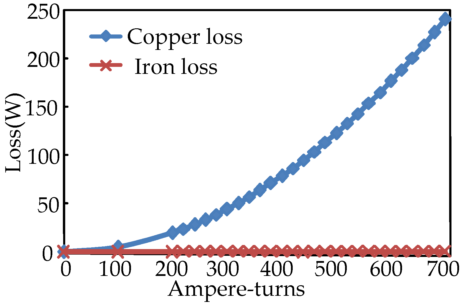
After some manipulation, substituting (6) into (17) and (18) yields:
N r i r s = Φ c r g 1 μ 0 S r a ,   N a i a x = Φ c a g 0 μ 0 S a x
According to (23) and (24), we can obtain the following equation when the maximum suspension forces are acting on the rotor:
N r i r s m = B r a 2 g 1 μ 0 ,   N a i a x m = B a x 2 g 0 μ 0
The required ampere-turns Nrirs and Naiax are proportional to g1 and g0, respectively. Bra2 and Bax2 are the magnetic flux densities in the radial and axial directions, respectively, corresponding to Φa2. irsm and iaxm are the maximum currents in the radial and axial suspension windings, respectively. g1 and g0 are set to 1.0 mm in the magnetic bearings.

5. Losses in HBM

The losses in HMB include rotor losses and stator losses. Rotor losses mainly include the air-friction loss and iron loss in the rotor; the stator losses mainly include copper loss caused by the control currents through the windings and iron loss in the stator.
In particular, the air-friction loss on the rotor can be estimated by the equation derived for rotating cylinders, which can be written as:
p a i r = k C f π ρ ω 3 r l
where k is the roughness coefficient, the value is 1.0 for a smooth surface and 2.5 for an axially-slotted surface, ρ is the density of fluid, Cf depends on the radius of rotor, radial air gap length and the Reynolds number, ω is the angular velocity of rotor, l is the length of the rotor and r is the radius of the rotor [27].
The iron losses on the rotor can be divided into the magnetic hysteresis loss and the eddy-current loss. The magnetic hysteresis loss was caused by the difference of the flux density. Meanwhile, the eddy-current loss was caused by the circulation of swirling flow because of the external time-varying magnetic field. The iron losses on the rotor can be written as follows:
p F e = ( k h f r B m 1.6 + 1 6 R π 2 e 2 f r 2 B m 2 ) V f e
where kh is the hysteresis loss coefficient, Bm is the peak flux density, fr is the operating frequency, R is the unit resistance of the iron core, e is the lamination thickness of the iron core and Vfe is the iron core volume, respectively. It can be seen that the rotor core loss mainly depends on the loss factor of core material, the operating frequency and the amplitude of the flux density.
The iron loss in the stator caused by the difference of the flux density and the power amplifiers can be negligible relative to the copper loss in the stator. There are four sets of windings with the maximum number of ampere turns NIrmax in the x and y axis respectively, two sets of windings with the maximum number of ampere turns NIamax in the z axis. The maximum allowable copper loss in the stator at the full load operation can be written as follows:
p C u = 8 ρ 1 l m r n r 2 A n K s t i r max 2 + 2 ρ 2 l m a n a 2 A n K s t i a max 2
where ρ1 is the resistivity of the winding in the x and y axis and ρ2 is the resistivity of the winding in the z axis. lmr, lma are the average length of the windings in radial and axial direction, respectively. An is the cross-sectional area of the windings, kst is the lamination factor of the stator, irmax, iamax are the maximum current of the radial and axial direction, respectively. When the HMB operates at rated speed and full load, the FEA-predicted variations of total copper losses and iron losses in this HMB are shown in Figure 7. Additionally, the copper losses in Figure 7 are extreme values because the radial and axial control currents are connected to the windings at the same time. It can be seen that the iron losses are much smaller compared with the copper losses in this HMB.

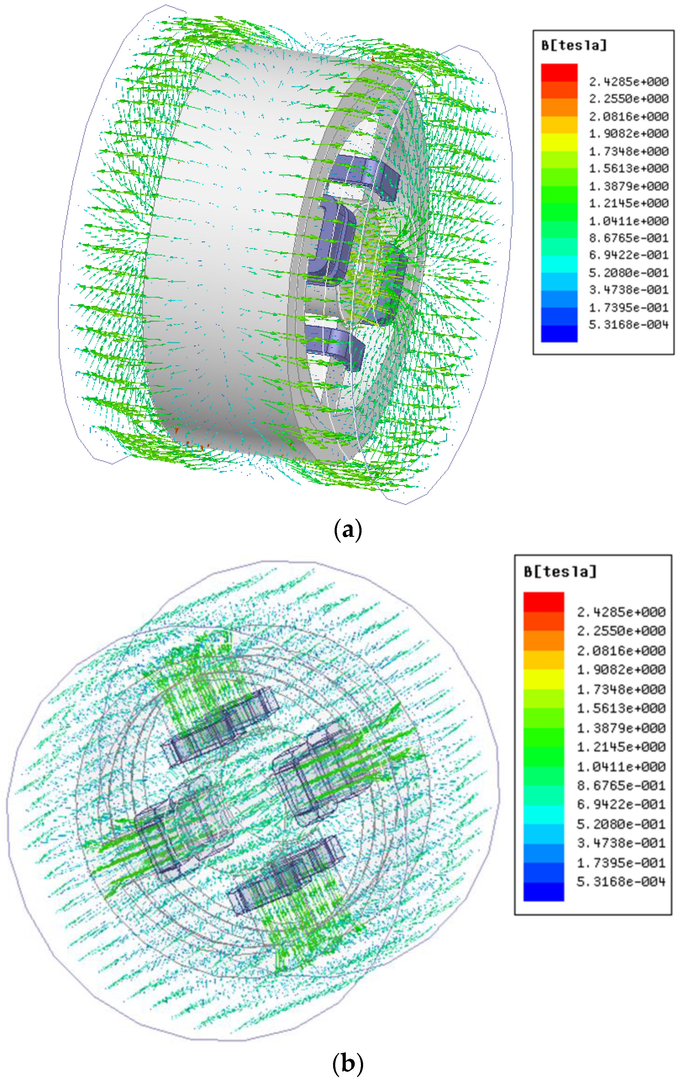
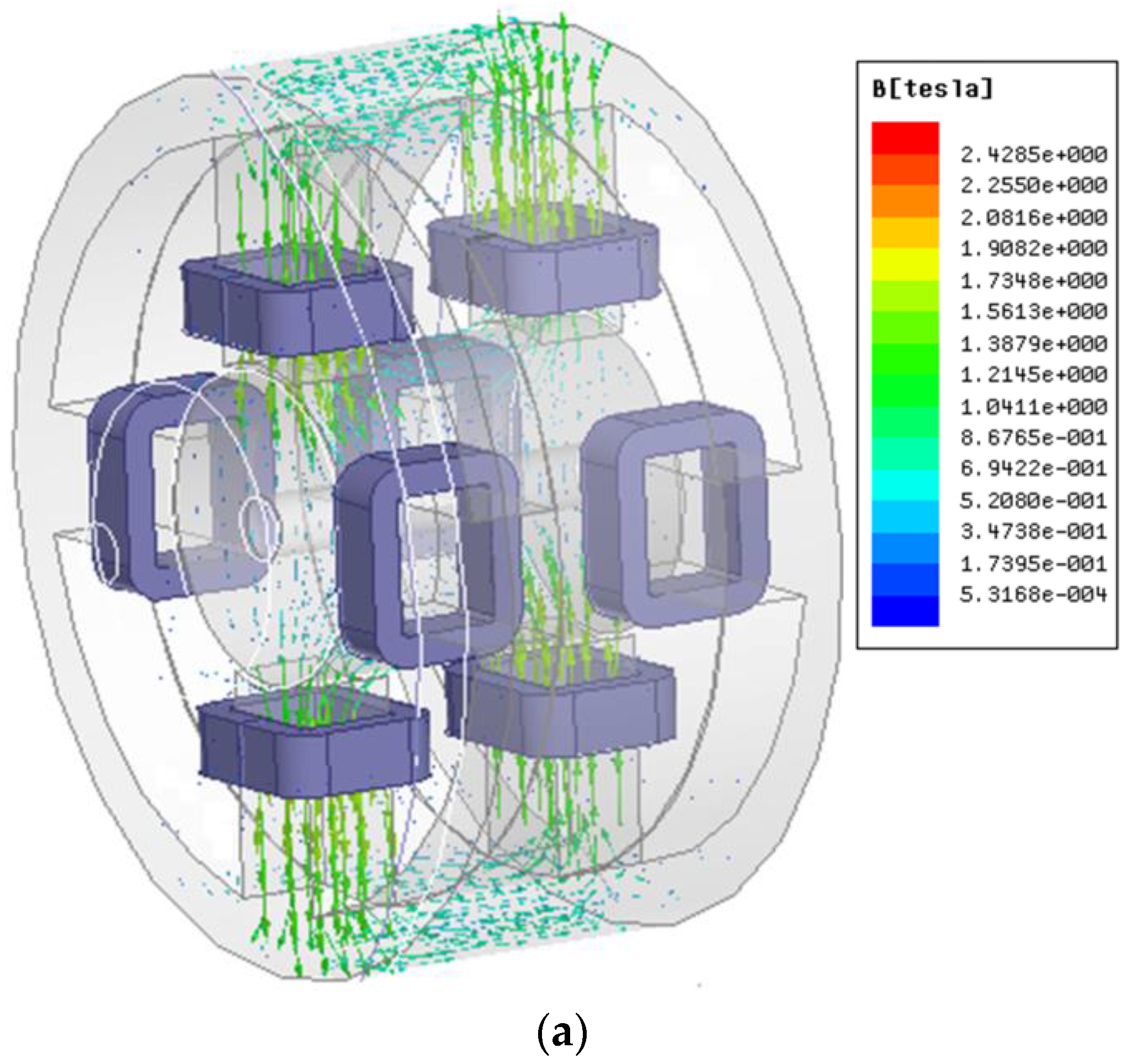
6. FEA, Unbalanced Force versus Displacement and Comparison

6.1. FEA

The key parameters of the proposed HMB used in 5-kW direct-drive wind turbines can be designed based on the structure parameter as shown in Table 1.
The finite element analysis (FEA) method, which is based on Maxwell differential equation and adopted the form of discrete, is widely used in various engineering electromagnetic fields. The FEA model of the proposed HMB can be set up based on the parameters given in Table 1. The 3D static magnetic field is used to calculate the magnetic field strength and observe the flux density distribution of the proposed HMB. The transient field is to calculate the force and torque when the rotor is twisted from the equilibrium position. The mesh operations in the proposed HMB are set as follows: the length of the stator and rotor cores are set as 4 mm; the length of the regions of the band and air gap are set as 1.5 mm; the length of control windings is set as 3 mm. The inner stator, outer stator and rotor are made of silicon steel DW360-50; the ring type permanent magnet is NdFeBN42SH. Figure 8 shows the 3D flux density distribution of the PM ring when the rotor is in the center position without eccentricity. Figure 9 presents the flux density distribution of the control windings in the radial and axial directions. Figure 10 shows the flux density distribution when the rotor deviates away from the equilibrium position.
The suspension force in radial and axial direction of the proposed HMB is calculated using the 3D FEA to analyze the validity and accuracy of the accurate equivalent magnetic circuit. As shown in Figure 11, Fax and Fra are the axial and radial suspension forces calculated based on (20) and (21), respectively; Fn1, Fa1 are the radial and axial suspension forces of the HMB proposed in this paper obtained using the FEA; Fn2, Fa2 are the radial and axial suspension forces of the HMB in [23] at the same parameters using FEA. Figure 11 also shows the relation between the axial and radial suspension forces and the ampere-turns when the rotor is at the equilibrium position. The magnitudes of the suspension force are linearly dependent on the ampere-turns. Moreover, the magnitudes of the calculated force based on the magnetic circuit analysis in this study are basically consistent with that of the FEA. The magnitudes of the axial force Fa2 in [23] are smaller than Fa1 in this paper, and the magnitudes of Fn2 are almost the same as Fn1 in this paper.

6.2. Unbalanced Force versus Displacement in Radial and Axial Directions

The unbalanced force will be occurred as the rotor shifts. The relationship between the offset and the unbalanced force in the axial and radial directions is analyzed in this study. Figure 12 shows the relationship between the axial direction offset z and the axial unbalanced force analyzed with 3D FEA. Fu1 and Fu2 are the axial unbalance forces in this paper and in [23], respectively. As shown in Figure 12, the axial unbalanced force Fu2 in [23] is near the Fu1 at the smaller offset of the rotor, but Fu2 is much smaller than Fu1 at the larger offset of the rotor. Figure 12 further demonstrates that the two unbalanced forces are almost linearly dependent on the axial direction displacement z. The maximum unbalanced force of Fu1 and Fu2 in the axial direction are 1150 N and 865 N respectively for the displacement z = 1 mm when the rotor shaft is touched down bearings. Figure 13 illustrates the radial offset angle θ versus the unbalanced force in the radial and axial directions. Fru1, Fau1 are the radial and axial unbalanced forces of the HMB in this paper, respectively. Fru2, Fau2 are the radial and axial unbalanced forces in [23]. It also presents that the radial unbalanced forces Fru1 and Fru2 are almost linearly dependent on the radial offset angle θ. Moreover, the axial unbalanced forces slowly increase according to the radial offset angle θ. The maximum axial unbalanced force Fau1 is 9.6 N and Fau2 is 89N when the rotor shaft is deflected at the maximum angle. As shown in Figure 13, the axial unbalance force in [23] is larger than the axial unbalance force in this paper.

7. Conclusions

This study proposes a five-degree-of-freedom hybrid magnetic bearing, which can realize suspension in the four-degree-of-freedom radial and one-degree-of-freedom axial directions. The two- degree-of-freedom suspension in the radial direction can be achieved by only one set of radial control windings. Therefore, only two sets of radial control windings are used in the proposed hybrid magnetic bearing. A cylindrical rotor core without a large thrust disc is used in the novel hybrid magnetic bearing. Accordingly, the system volume, numbers of controller and power amplifier will be reduced in the magnetic levitation system. The precision equivalent magnetic circuit model and the accuracy of the analytical method are validated by the 3D finite element analysis based on the given parameters in Table 1. The prototype of the proposed hybrid magnetic bearing will be presented in the future work based on the model derived in this study.

Acknowledgments

This work was supported by the Priority Academic Program Development of Jiangsu Higher Education Institutions, the Natural Science Foundation of Jiangsu Province (BK20150524) and the Professional Research Foundation for Advanced Talents of Jiangsu University under Project (14JDG131), National Natural Science Foundation of China (51607080).

Author Contributions

Yanjun Yu and Weiyu Zhang are responsible for the theoretical analysis and calculation of the proposed 5-DOF hybrid magnetic bearing. Yanjun Yu and Yuxin Sun are responsible for the finite element analysis of the proposed HMB. Yanjun Yu and Peifeng Xu wrote the paper. All authors read and approved the final manuscript.

Conflicts of Interest

The authors declare no conflict of interest.

References

  1. Ouyang, H.; Liu, F.; Zhang, G.M. Vibration suppression for rotor system of magnetic suspended wind turbines using cross-feedback-based sliding mode control. In Proceedings of the IEEE International Symposlum on System Integration, Nagoya, Japan, 11–13 December 2015; pp. 112–115.
  2. Muyeen, S.M. Wind Energy Conversion Systems Technology and Trends; China Machine Press: Beijing, China, 2013. [Google Scholar]
  3. Zhu, H.; Ding, S.; Jv, J. Modeling for three-pole radial hybrid magnetic bearing considering edge effect. Energies 2016, 9, 345. [Google Scholar] [CrossRef]
  4. Ding, W.; Liu, L.; Lou, J.Y. Design and control of a high-speed switched reluctance machine with conical magnetic bearings for aircraft application. IET Electr. Power Appl. 2012, 7, 179–190. [Google Scholar] [CrossRef]
  5. Chow, S.T.; Shyh, L.C. Design and control of a ring-type flywheel battery system with hybrid halbach magnetic bearings. In Proceedings of the IEEE/ASME International Conference on Advanced Intelligent Mechatronics, Besancon, France, 8–11 July 2014; pp. 1558–1562.
  6. Ji, L.; Xu, L.X.; Jin, C.W. Research on a low power consumption six-pole heteropolar hybrid magnetic bearing. IEEE Trans. Magn. 2013, 49, 4918–4926. [Google Scholar] [CrossRef]
  7. Yonmook, P. Design and implementation of an electromagnetic levitation system for active magnetic bearing wheels. IET Control Theory Appl. 2014, 8, 139–148. [Google Scholar]
  8. Wu, D.; Liu, X.; Zhu, Z.Q.; Pride, A.; Deodhar, R.; Sasaki, T. Switched flux hybrid magnet memory machine. IET Electr. Power Appl. 2015, 9, 160–170. [Google Scholar] [CrossRef]
  9. Sun, J.; Zhang, Y. A novel integrated structure with a radial displacement sensor and a permanent magnet biased radial magnetic bearing. Sensors 2014, 14, 1950–1960. [Google Scholar] [CrossRef] [PubMed]
  10. Xu, S.L.; Sun, J.J. Decoupling structure for heteropolar permanent magnet biased radial magnetic bearing with subsidiary air-gap. IEEE Trans. Magn. 2014, 50, 8300208. [Google Scholar] [CrossRef]
  11. Liu, G.; Mao, K. A novel power failure compensation control method for active magnetic bearings used in high-speed permanent magnet motor. IEEE Trans. Power. 2016, 31, 4565–4575. [Google Scholar] [CrossRef]
  12. Jiang, K.J.; Zhu, C.S.; Chen, L.L. Unbalance compensation by recursive seeking unbalance mass position in active magnetic bearing-rotor system. IEEE Trans. Ind. Electron. 2015, 62, 5655–5664. [Google Scholar]
  13. Liu, Ch.; Liu, G. Equivalent damping control of radial twist motion for permanent magnetic bearings based on radial position variation. IEEE Trans. Ind. Electron. 2015, 62, 6417–6427. [Google Scholar] [CrossRef]
  14. Bachovchin, K.D.; Hoburg, J.F.; Post, R.F. Stable levitation of a passive magnetic bearing. IEEE Trans. Magn. 2013, 49, 609–617. [Google Scholar] [CrossRef]
  15. Imoberdorf, P.; Nussbaumer, T.; Johann, W. Analysis of a combined radial-axial magnetic bearing for a high-speed system. In Proceedings of the 5th IET International Conference on Power Electronics, Machines and Drives (PEMD), Brighton, UK, 19–21 April 2010.
  16. Daoud, M.I.; Abdel-Khalik, A.S.; Massoud, A.; Ahmed, S.; Abbasy, N.H. A design example of an 8-pole radial AMB for flywheel energy storage. In Proceedings of the 2012 20th International Conference on Electrical Machines (ICEM), Marseille, France, 2–5 September 2012; pp. 1153–1159.
  17. Zhang, W.Y.; Zhu, H.Q. Precision modeling method specifically for AC magnetic bearings. IEEE Trans. Magn. 2013, 49, 5543–5553. [Google Scholar] [CrossRef]
  18. Kim, S.H.; Shin, J.W.; Ishiyama, K. Magnetic bearings and synchronous magnetic axial coupling for the enhancement of the driving performance of magnetic wireless pumps. IEEE Trans. Magn. 2014, 50, 8300208. [Google Scholar] [CrossRef]
  19. Zhang, W.Y.; Zhu, H.Q. Control system design for a five-degree-of-freedom electrospindle supported with AC hybrid magnetic bearings. IEEE/ASME Trans. 2015, 20, 2525–2537. [Google Scholar] [CrossRef]
  20. Lin, F.J.; Chen, S.Y.; Huang, M.S. Intelligent double integral sliding-mode control for five-degree-of-freedom active magnetic bearing system. IET Control Theory Appl. 2011, 5, 1287–1303. [Google Scholar] [CrossRef]
  21. Liu, S.; Song, L.; Li, S.; Wang, J.; Lei, X. Decoupling active and passive hybrid axial and radial magnetic bearing. In Proceedings of the 4th International Conference on Control, Automation and Information Sciences (ICCAIS), Changshu, China, 29–31 October 2015; pp. 402–407.
  22. Dash, S.K.; Swarup, K.S.; Rajan, K.K. Design optimization of large gap single axis thrust magnetic bearing actuator. Int. J. Appl. Electromagn. Mech. 2015, 47, 661–675. [Google Scholar]
  23. Wang, G.; Xu, L.X. Structure and magnetic circuit analysis of permanent magnet biased magnetic bearing with five degrees of freedom. Dev. Innov. Mach. Electr. Prod. 2003, 6, 16–18. [Google Scholar]
  24. Masuzawa, T.; Kojima, J.; Onuma, H. Micro magnetic bearing for an axial flow artificial heart. In Proceedings of the 9th International Symposium on Magnetic Bearings, Lexington, KY, USA, 3–6 August 2004; pp. 89–94.
  25. Wang, X.; Fang, J.C.; Fan, Y.H.; Sun, J.J. Axial force tilting permanent-magnet-biased magnetic bearing with five degrees of freedom and magnetic field decoupling design. Proc. CSEE 2011, 31, 91–98. [Google Scholar]
  26. Schweitzer, G.; Maslen, E.H. Magnetic Bearings: Theory, Design, and Application to Rotating Machinery; China Machine Press: Beijing, China, 2012. [Google Scholar]
  27. Nerg, J.; Rilla, M.; Pyrhonen, J. Thermal analysis of radial-flux electrical machines with a high power density. IEEE Trans. Ind. Electron. 2008, 55, 3543–3554. [Google Scholar] [CrossRef]
Figure 1. Configuration and the exploded view of the proposed 5-DOF HMB.
Energies 09 00905 g001
Figure 2. The inner stator core and cutaway view of the proposed 5-DOF HMB. (a) Cutaway view of the proposed 5-DOF HMB; (b) the structure of the inner stator core.
Energies 09 00905 g002
Figure 3. Principle of radial suspension force generation.
Energies 09 00905 g003
Figure 4. Equivalent magnetic circuit of the PM ring.
Energies 09 00905 g004
Figure 5. Distribution of flux density vectors of the PM.
Energies 09 00905 g005
Figure 6. Equivalent magnetic circuit model of control magnetic field. (a) The equivalent magnetic circuit model of the radial active control circuit; (b) the equivalent magnetic circuit model of the axial active control circuit.
Energies 09 00905 g006
Figure 7. Variation of losses with ampere-turns.
Energies 09 00905 g007
Figure 8. Flux density distribution of the PM ring. (a) Flux density distribution of PM ring in the outer stator; (b) flux density distribution of PM ring in the inner stator teeth.
Energies 09 00905 g008
Figure 9. Flux density distribution at rated current. (a) Flux density distribution of one set of radial control windings; (b) flux density distribution of one set of axial control windings.
Energies 09 00905 g009aEnergies 09 00905 g009b
Figure 10. Flux density distribution when the rotor deviates away from the equilibrium position. (a) Flux density distribution when the rotor offsets in the axial direction; (b) flux density distribution when the rotor twists in the radial direction.
Energies 09 00905 g010
Figure 11. A comparison between the precision equivalent magnetic circuit and two kinds of HMB. (a) Axial suspension force versus ampere-turns; (b) radial suspension force versus ampere-turns.
Energies 09 00905 g011
Figure 12. Axial direction displacement versus axial unbalanced force.
Energies 09 00905 g012
Figure 13. Radial offset angle versus and radial unbalanced force.
Energies 09 00905 g013
Table 1. Key parameters of the proposed HMB.
ParametersValue
Axial air gap length, g1, mm1
Radial air gap length, g0, mm1
Height of PM, hm, mm10
Maximum number of ampere turns, Nrirs, Naiax700
Axial length of outer stator, mm240
Outer diameter of outer stator, mm342
Axial length of rotor, mm120
Outer diameter of rotor, mm100
Axial length of PM ring, mm120
Height of the inner stator tooth, mm70
Width of the inner stator tooth, mm30
Yokes of inner and outer stator, mm20
Relative permeability of PM, μr1.1
Remanence for PM, Br, T1.25

