Article

A Three-Stage Optimal Approach for Power System Economic Dispatch Considering Microgrids

1
Department of Industrial Education and Technology, National Changhua University of Education, Changhua 500, Taiwan
2
The Institute of Nuclear Energy Research, Taoyuan City 325, Taiwan
*
Author to whom correspondence should be addressed.
Energies 2016, 9(11), 976; https://doi.org/10.3390/en9110976
Submission received: 20 September 2016 / Revised: 14 November 2016 / Accepted: 15 November 2016 / Published: 22 November 2016
(This article belongs to the Special Issue Innovative Methods for Smart Grids Planning and Management)

Abstract

:
The inclusion of microgrids (MGs) in power systems, especially distribution-substation-level MGs, significantly affects power systems because of the large volumes of import and export power flows. Consequently, power dispatch has become complicated, and finding an optimal solution is difficult. In this study, a three-stage optimal power dispatch model is proposed to solve such dispatch problems. In the proposed model, the entire power system is divided into two parts, namely, the main power grid and MGs. The optimal power dispatch problem is resolved on the basis of multi-area concepts. In stage I, the main power system economic dispatch (ED) problem is solved by sensitive factors. In stage II, the optimal power dispatches of the local MGs are addressed via an improved direct search method. In stage III, the incremental linear models for the entire power system can be established on the basis of the solutions of the previous two stages and can be subjected to linear programming to determine the optimal reschedules from the original dispatch solutions. The proposed method is coded using Matlab and tested by utilizing an IEEE 14-bus test system to verify its feasibility and accuracy. Results demonstrated that the proposed approach can be used for the ED of power systems with MGs as virtual power plants.

1. Introduction

Energy efficiency, economic dispatch (ED), and greenhouse gas emissions are major issues associated with utilities. Although electrical energy has been used for over one hundred years since the first electric network was established in 1882 at the Pearl Street Station in New York by Thomson Edison [1], the development of power systems has evolved into generation, transmission, and distribution with a vertical system architecture. In a vertical system structure, a generation system is composed of major large centralized thermal power plants, minor large reservoir hydroelectric power plants, and a small portion of renewable energy generation. Carbon dioxide and other greenhouse gas emissions caused by thermal power plants exacerbate global warming because of the usage of carbon-based fuels in such plants. The electrical energy produced is delivered through transmission and distribution systems until it reaches customers. Electrical energy losses during transmission are considerable. Such losses not only affect the environment, but also reduce the overall system efficiency. Consequently, the traditional large centralized power system architecture is impractical in terms of high efficiency, energy savings, and environmental protection. Conversely, Distributed Energy Resources (DERs) composed of distributed generations (DGs) and energy storage devices [2] are incorporated in local high- or low-voltage distribution networks to satisfy the load demand. As such, DERs can reduce the losses caused by power delivery, and renewable energy-based wind turbine, solar power, or relatively clean units, such as fuel cells and microturbines, can be utilized to reduce greenhouse gas emissions and environmental impact.
DERs interconnected into an existing power grid to form an area grid, which can be operated in grid-tied or autonomous modes, are called MGs [3]. The power grid integrated with information and communication technologies is a smart grid. The development of low-carbon central generation and local energy networks has emerged as a new trend. Europe, the USA, Japan, and Canada have been actively involved in pilot system construction and related research. For instance, the European SmartGrids Technology Platform for future power grids began its work in 2005. This platform aims to formulate and promote a vision for the development of electricity networks in Europe in 2020 and beyond [4]. Future power systems will be composed of low-emission power plants, solar energy, wind turbines, biomass, ocean wave energy, hydroelectric, microturbines, gas turbines, fuel cells, and energy storage devices. As a result, the operation of the future electricity network will be shared between central and distributed generators. Thus, the control of distributed generators can be aggregated to form MGs or virtual power plants (VPPs) to facilitate their integration in physical systems and in markets. Overall, the planning, design, control, and operation of MGs are essential, especially the on-line management or optimal dispatch of various types of DG in an MG under grid-tied and autonomous operation modes. The optimal dispatch of future power grids integrated with MGs as VPPs for safety, economic, and energy loss reduction planning and operation is also relevant in power system research.
ED problems in traditional power systems should be solved in terms of the total minimum operation costs by adjusting the output of each generator to satisfy the load demand and related operational constraints. Since 1920, several power engineering experts and scholars have conducted relevant research. ED problems are based on circuit and optimal theories. The primary task aims to obtain real-time system states, and the power flow algorithm is applied to determine the exact bus voltages and line flows of power systems via traditional AC power flow method [5,6,7,8]. Although solutions generated by such methods are precise, they require time-consuming processes and iterations and exhibit a convergence problem. Newton-Raphson method and Gauss-Seidel method are not applicable for the real-time calculation of power flows. The methods of network sensitivity factors, such as generation shift distribution factor [9], generalized generation shift distribution factor [10], Z-bus distribution factor [11], and Jacobian-based distribution factor (JBDF) [12], have been proposed to improve the computation speed and to eliminate the need for iterations. The application of these approaches overcomes the weakness of Newton and Gauss-based power flow algorithms in ED. Common optimal algorithms in ED and unit commitment are based on Lagrange multiplier-based methods [13,14] and meta-heuristic approaches [15]. Soroudi and Rabiee [16] proposed a new model to solve the multi-area dynamic ED problem by considering the uncertainties in wind power generation, energy prices, and system demands. Optimality condition decomposition is also utilized to verify the proposed approach for the real-time operation of practical power systems. Niu et al. [17] presented an improved quantum-behaved particle swarm optimization (QPSO) to solve the ED problems with valve-point effects and multiple fuel options. This method connects the basic QPSO [18] with a selective probability operator to preserve the fast convergence characteristics and to reduce suffering from premature convergence. Cheng and Zhang [19] combined a dynamic economic dispatch model and an improved particle swarm optimization (PSO) approach to solve the ED problem considering the uncertain nature of wind generation. Li et al. [20] proposed a Quasi-Newton method to update the multiplier, together with an initialization strategy for the multipliers and the approximation matrix. It can be used in dynamic economic dispatch to large-scale integration of renewable generation in power systems. Zaman et al. [21] presented a self-adaptive differential evolution and a real-coded genetic algorithm to solve the dynamic dispatch problem, simulation results demonstrated that the approach is with high solution quality and reliability. Liu et al. [22] introduced an inexact mix-integer two-stage programming model to address low-carbon energy systems in terms of costs, energy security, and carbon dioxide emission. In a previous study [23], fruit fly algorithm is applied to solve an optimal dispatch problem in power systems with a VPP. This algorithm is a nonlinear mixed-integer programming with inter-temporal constraints, and the proposed approach can manage the optimal dispatch strategy among DGs in a VPP and a trading plan with electricity market. Although, these algorithms provide solution quality, convergence speed, and robustness depending on their applications. However, all the related studies mentioned above seldom consider the distribution substation-level MGs in ED problems in modern power systems. This is vital because of the inclusion of MGs in power systems will significantly affect the power dispatch due to the large magnitude of the import and export power flows. Therefore, in this study, an innovative three-stage approach is proposed for the ED of modern power systems comprising MGs as VPPs. The ED model that is derived by the network sensitivity factors in main power grid is with high efficiency and without iteration problem after load changes; besides, the improved direct search method (IDSM), which is with easy and fast characteristics is proposed for optimal dispatch in MGs. Finally, the power exchanges between the main power grid and MGs are modeled by linear incremental model for solving the entire system ED problem by linear programming method. Consequently, this new approach can be utilized for smart grid applications. This paper is divided into five sections. Section 1 introduces the background and objectives of this study. Section 2 describes the traditional Lagrange multiplier-based ED and optimal dispatch in MGs and then derives the proposed three-stage ED model. Section 3 explains the solution procedure of the proposed model. Section 4 discusses the simulation results. Section 5 presents our conclusions.

2. Problem Description and Formula Derivation

MGs play important roles as VPPs in power system operations. Therefore, power systems will be composed of the main power grid and several MGs. The generation dispatch corresponding to load demand will become highly complicated in the near future. In this section, the ED problem is divided into four parts, namely, system structure, ED model of the main power grid, ED model of the MG, and integrated ED model of the power system.

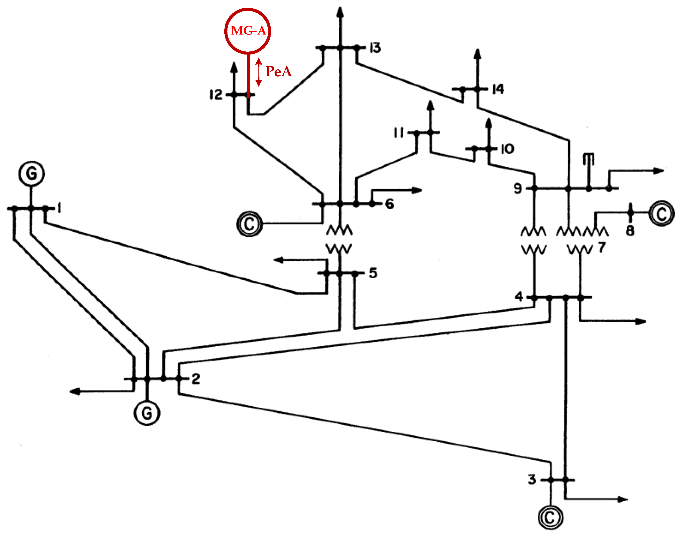
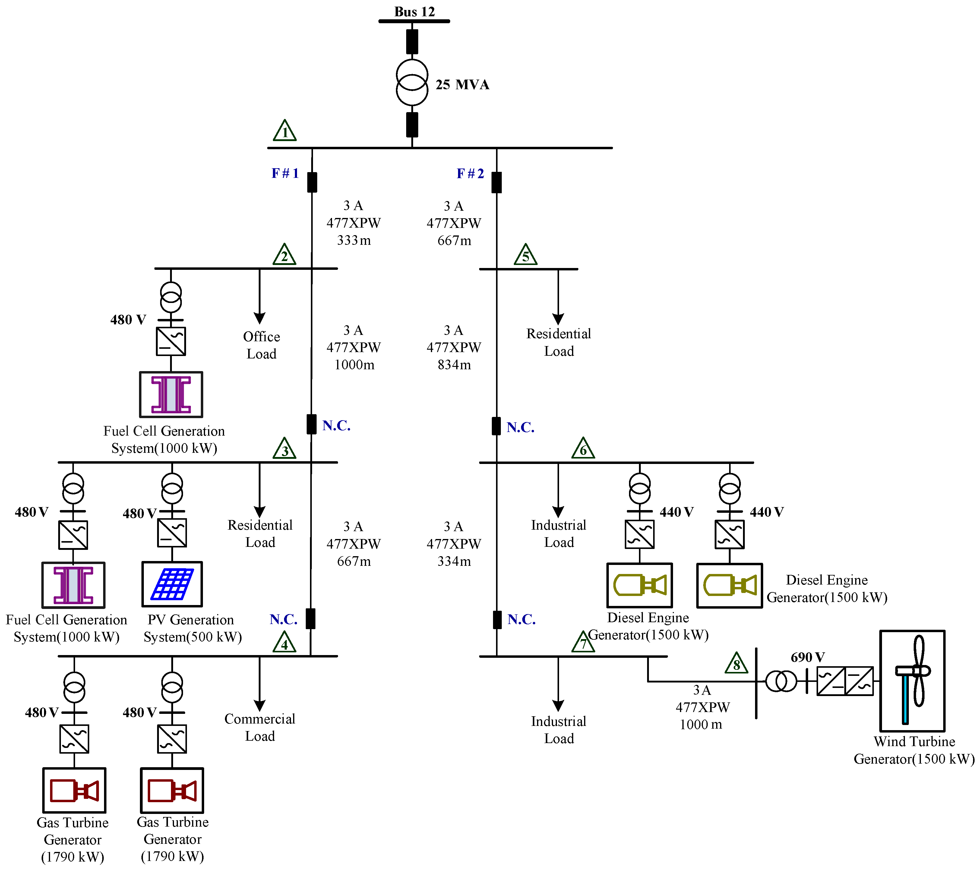
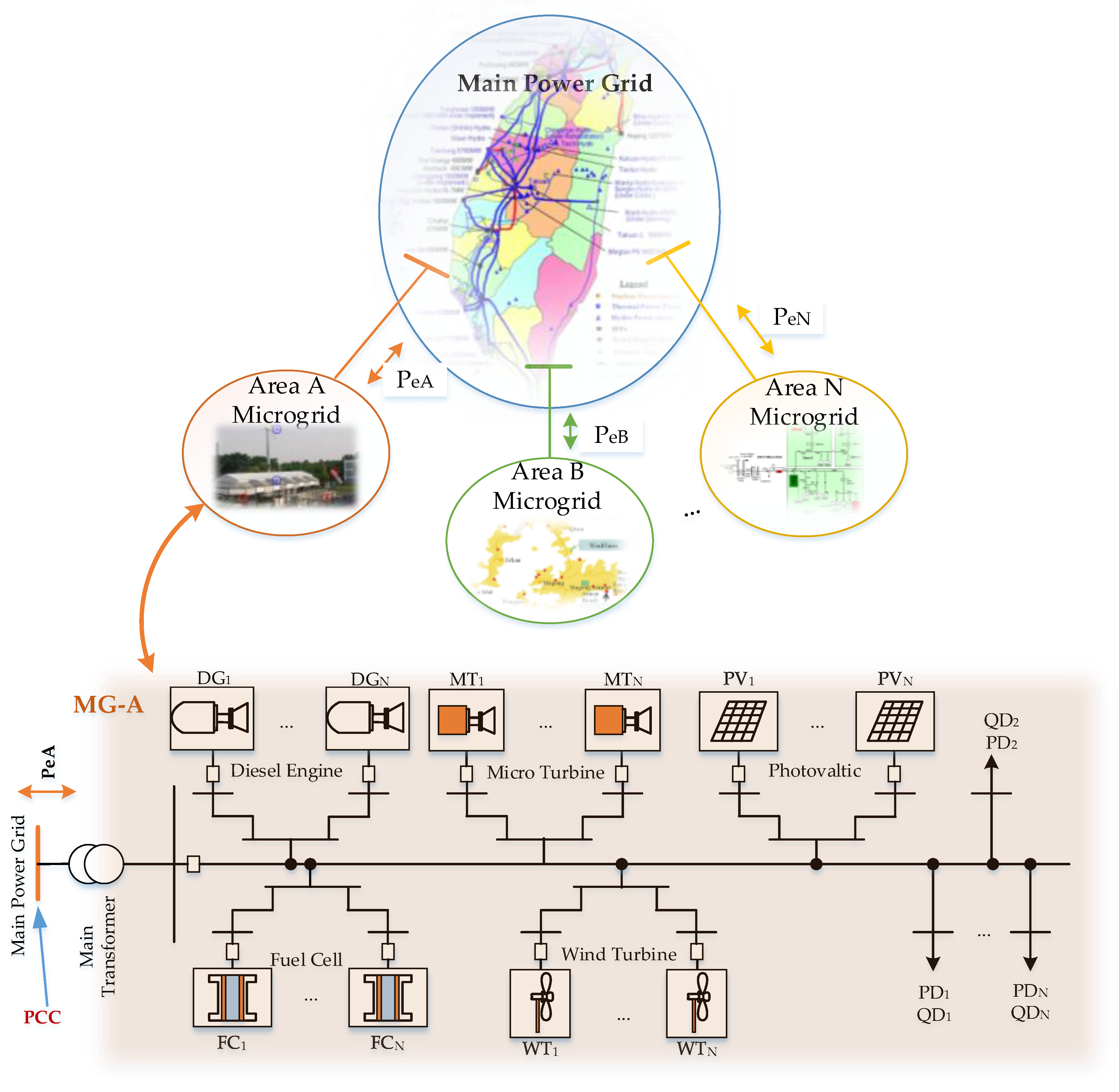
2.1. System Structure

Figure 1 illustrates the system structure of a power system that consists of the main power grid and N distribution substation-level MGs. In terms of transmission systems, the distribution networks with DERs and loads can be regarded as MGs at the primary side of the main transformer as the point of common coupling. According to a multi-area ED model, power systems can be partitioned into the main power grid and a MG in each area. The MG in each area is considered a VPP, which is composed of diesel engine generators, fuel cells, microturbine generators, wind turbine generators, photovoltaic systems, and loads.

2.2. ED of the Main Power Grid

The ED in the main power grid can be described as follows:
min   J = i = 1 N G f i ( P G i ) ,
subject to:
i = 1 N G P G i P D P L = 0 ,
P G i min P G i P G i max   i = 1 , ... , N G ,
P m max P m P m max   m = 1 , ... , N L .
where ƒi and PGi represent the cost function and power generation of the ith thermal generator unit, respectively; PD denotes the total power demand in the main power grid; PL is the transmission loss; and Pm is the real power flow in the ith transmission line. Using Lagrange multiplier and adding equality constraints, we can rewrite the optimal problem of ED as follows [24]:
L = i = 1 N G f i ( P G i ) + λ ( P D + P L i = 1 N G P G i )
On the basis of Equation (5), we let partial L to P G i be 0, as shown in Equation (6):
L P G i = 0
Using Equation (6), we derive Equation (7):
f i P G i = λ ( 1 P L P G i ) ,
we let:
L λ = 0 ,
equality constraints, where the generation is equal to the total demands plus losses, can be obtained, as shown in Equation (2). In Equation (7), P L / P G i is the incremental transmission loss (ITL), and Equation (7) is rearranged as:
( 1 1 I T L i ) ( f i P G i ) = λ ,
we rewritten Equation (9) as:
P f i ( f i P G i ) = λ ,
where Pfi is equal to 1 / ( 1 I T L i ) corresponding to the penalty factor. Although ED problems can be solved by artificial intelligence-based optimal algorithms, the Lagrange multiplier-based methods remain the most reliable, most accurate, and fastest in practical system applications. On the basis of Equations (9) and (10), we observe that the solution kernel of ED depends on the rapid calculation of ITLi, Pfi, and PL, and the first task is to derive the mathematical model of PL to rapidly compute ITLi and Pfi. The formula derivation is described in the following sections.

2.3. ED in a Microgrid

The DERs included in MGs are shown in Figure 1. In terms of the multi-area ED concept, the large thermal power plants, transmission systems, and distribution substations in case of the Taipower system regarded as equivalent loads can be formed as the main power grid, and partial distribution stations whose distribution networks with DERs and loads are developed as MGs. Consequently, the primary task of the integrated ED problem in modern power systems is the optimal dispatch in MGs. Thus, the first step is to establish the cost function in an MG.
Similar to large thermal units, the fuel cost of a diesel engine generator is the quadratic polynomial function of its actual power output. However, the fuel cost of a fuel cell generation system is the linear function of its actual power output and efficiency. Therefore, the aggregate cost function of the MG is combined with nonlinear and linear functions. This problem can be solved by direct or indirect search algorithms, where the direct search algorithm called nongradient or zeroth-order method only considers objective function and the indirect search algorithm should consider the partial derivatives of objective function. In this study, an IDSM is proposed to solve the optimal dispatch problem in MGs effectively. In general, a direct search method (DSM) [25] is unsuitable for large-scale systems. The first step of this search approach is to set the incremental cost (IC) value (ΔP). The unit with the minimum IC value is then selected to increase the generation until the IC of each unit is equal and thus satisfies the power balance equation. The weakness of this search method is the start point, that is, it usually starts from 0. As such, the searching time becomes lengthy. The proposed IDSM can improve the limitation of the DSM. The first step is to obtain the ICs of all units, including fuel cell and microturbine with linear costs, as shown in Equations (11) and (12):
f F C i = β i P F C i ,     i = 1 , ... , N F C
f M T i = γ i P M T i ,     i = 1 , ... , N M T
where f F C i denotes the fuel cost of the ith fuel cell; β i and P F C i represent the cost coefficient and power generation of the ith fuel cell unit, respectively. f M T i , γ i , and P M T i are the fuel cost, cost coefficient, and power generation of the ith microturbine unit, respectively. NFC and NMT represent the unit number of fuel cell and microturbine in an MG, respectively. IC can be derived as follows:
I C F C i = f F C i P F C i = β i ,
I C M T i = f M T i P M T i = γ i .
The ICs of fuel cell and microturbine are constant, as shown in Equations (13) and (14). Therefore, they can be sequentially arranged as follows:
I C A = [ I C 1 , I C 2 , ... , I C N ] ,
where I C 1 < I C 2 < ... < I C N , and N is the summation of N F C and N M T in MG-A. The fuel cost of diesel engine generator can be expressed as follows:
f D G i = a D G i + b D G i P D G i + c D G i P D G i 2     i = 1 , ... , N D G ,
where f D G i denotes the fuel cost of the ith diesel engine unit; a D G i , b D G i , and c D G i are the cost coefficients. NDG represents the unit number of the diesel engine unit in an MG. The IC can be derived as follows:
I C D G i = f D G i P D G i = b D G i + 2 c D G i P D G i ,
substituting the I C 1 of Equation (15) in Equation (17) results in:
P D G i 0 = I C 1 b D G i 2 c D G i ,
the initial generation, P D G i 0 , is started, as shown in Equation (18). PDGi is gradually adjusted according to the proposed IDSM method until this procedure satisfies the power balance equation, as shown in Equation (19):
i = 1 N D G P D G i + i = 1 N F C P F C i + i = 1 N M T P M T i = P D A + P L A P P V P W T ,
where P D A is the total power demand in MG-A, P D A is the real power loss in MG-A, P P V is the power generation of photovoltaic in MG-A, and P W T is the power generation of wind turbine in MG-A.

2.4. ED Integrated with Main Power Grid and MGs

In this section, the integrated model of the main power grid and MGs is derived on the basis of Section 2.2 and Section 2.3. According to the multi-area dispatch concept, the completed ED problem involves three stages:
  • Stage I: ED in main power grid
  • Stage II: ED in each MG
  • Stage III: integrated ED of main power grid and MGs
The ED in stage III is based on those in stages I and II. The detailed derivation in each stage to establish the linear increment model is described as follows.

2.4.1. Thermal Unit in Main Power Grid

The linear cost model of the thermal power unit in the main power grid is expressed as Equation (20). The coefficient of each unit depends on the power plant type:
Δ f i = f i P G i Δ P G i = ( b i + 2 c i P G i 0 ) Δ P G i

2.4.2. NonRenewable Unit in MGs

The linear cost models of diesel engine, fuel cell, and microturbine units in an MG are expressed as Equations (21)–(23), respectively:
Δ f D G i = f D G i P D G i Δ P D G i = ( b D G i + 2 c D G i P D G i 0 ) Δ P D G i
Δ f F C i = f F C i P F C i Δ P F C i = β i Δ P F C i
Δ f M T i = f M T i P M T i Δ P M T i = γ i Δ P M T i

2.4.3. Linear Programing Model of ED

The linearized dispatch model is established in stage III on the basis of the linear cost model described in Section 2.4.1 and Section 2.4.2 and is solved by the linear programming method. The objective function is expressed as follows:
min   J = i = 1 N G Δ f i + i = 1 N D G Δ f D G i + i = 1 N F C Δ f F C i + i = 1 N M T Δ f M T i ,
subject to:
i = 1 N G Δ P G i Δ P L P e A = 0 ,
i = 1 N D G Δ P D G i + i = 1 N F C Δ P F C i + i = 1 N M T Δ P M T i Δ P L A + Δ P e A Δ P D A = 0 ,
Δ P G i min Δ P G i Δ P G i max ,
Δ P D G i min Δ P D G i Δ P D G i max ,
Δ P F C i min Δ P F C i Δ P F C i max ,
Δ P M T i min Δ P M T i Δ P M T i max ,
where P e A is the power interchange between the main power grid and MG-A, and positive P e A means that power is fed into MG-A. These equations can be expressed as a standard linear model as follows:
min   J = C T x ,
subject to:
{ a 11 x 1 + a 12 x 2 + + a 1 N x N = b 1                     a N 1 x 1 + a N 2 x 2 + + a N N x N = b N ,
{ x 1 min x 1 x 1 max   x N min x N x N max ,
each extreme point is gradually searched in accordance with the linear programming method. The optimal power generation of each unit is derived, as shown in Equations (34)–(37). The optimal ED solution of power systems considering MGs as VPPs can be obtained:
P G i = P G i 0 + Δ P G i ,
P D G i = P D G i 0 + Δ P D G i ,
P F C i = P F C i 0 + Δ P F C i ,
P M T i = P M T i 0 + Δ P M T i .

3. Solution Procedure
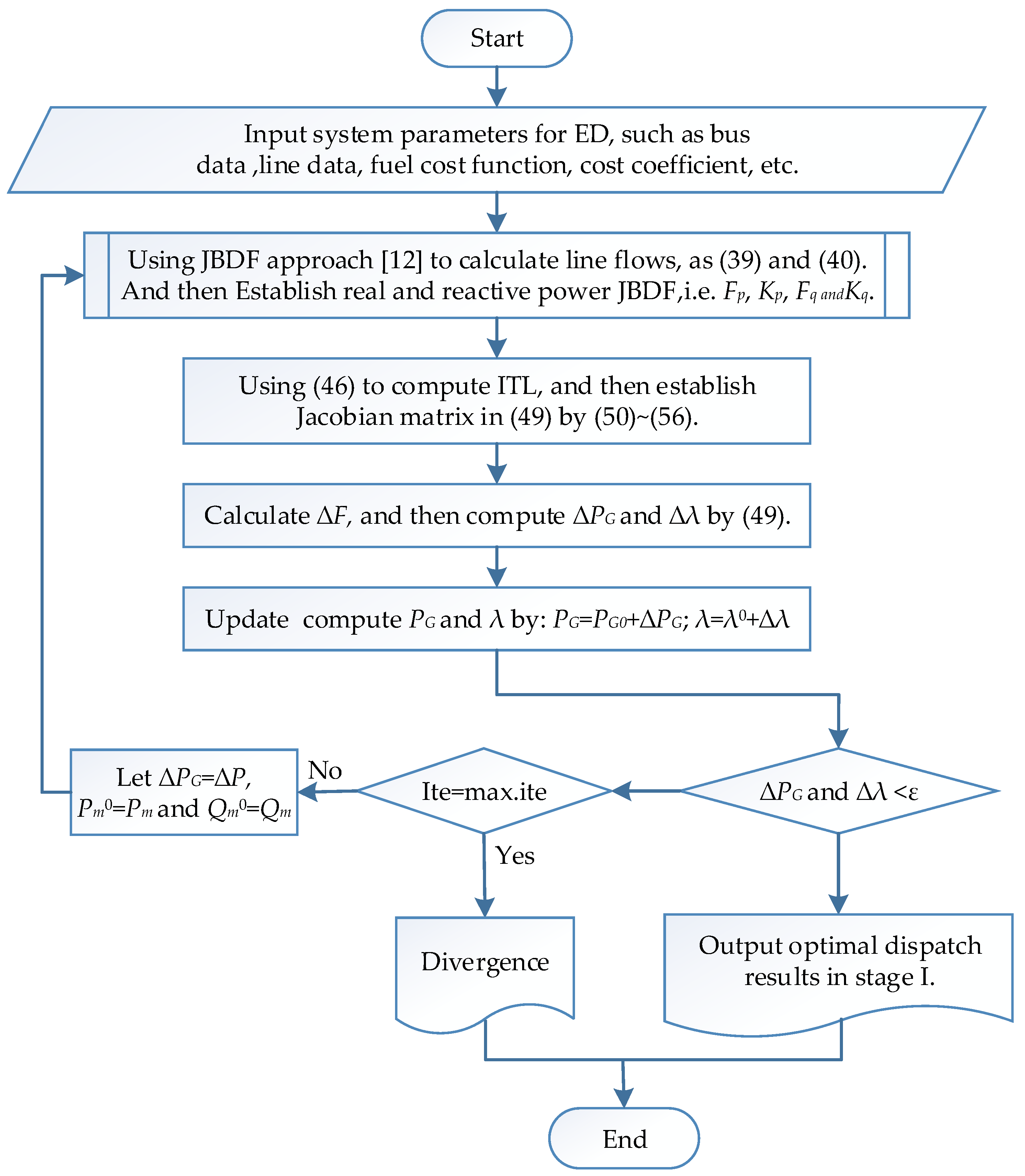
In this section, the detailed solution algorithm and model of the main power grid and MGs are explained. The proposed approach can be applied in multi-area complex power systems. The solution procedure is described as follows.

3.1. Stage I

The JBDF [12]-based Lagrange multiplier method is proposed to solve the ED in the main power grid. A power flow program should be executed to solve the ED problem in each iteration by the traditional Lagrange multiplier method. However, this procedure is time consuming and may result in divergence condition. The key point is to obtain the ITL and penalty factor (Pf) efficiently after the load demand and generation are changed. The JBDF-based formula is derived to obtain ITL and Pf in the ED procedure instead of running a power flow program and to overcome the weakness of ITL and Pf derivation after load demand changes.

3.1.1. Models of Transmission Line Loss and Line Flow

Pm and Qm represent the line m flows of real and reactive powers, and the transmission line loss PL is expressed as follows:
P L = m = 1 N L R m ( P m 2 + Q m 2 )   m = 1 , ... , N L ,
where Rm denotes the resistance of line m, and NL is the number of transmission lines. The real and reactive power line flows can be expressed as [12]:
P m = P m 0 + i = 1 N G F p ( m , i ) Δ P G i + i = 1 N G K p ( m , i ) Δ Q G i
Q m = Q m 0 + i = 1 N G F q ( m , i ) Δ P G i + i = 1 N G K q ( m , i ) Δ Q G i ,
in the ED procedure, the real power is generally only adjustable using generators corresponding to load demand changes, and the reactive power is kept constant. Consequently, Equations (39) and (40) are simplified as Equations (41) and (42), respectively. Δ P G i is the change in the real power of the ith generator from the base case:
P m = P m 0 + i = 1 N G F p ( m , i ) Δ P G i
Q m = Q m 0 + i = 1 N G F q ( m , i ) Δ P G i
Δ P G i = P G i P G i 0
where Fp and Fq are the distribution factors of JBDF, which are expressed as Equations (44) and (45), respectively:
F p ( m , i ) = | V p | P i P m | V p | + | V q | P i P m | V q | + δ p P i P m δ p + δ q P i P m δ q
F q ( m , i ) = | V p | P i Q m | V p | + | V q | P i Q m | V q | + δ p P i Q m δ p + δ q P i Q m δ q
where | V p | / P i , | V q | / P i , δ p / P i and δ q / P i represent the magnitude and phase angle of the bus voltage sensitive to real power injections. These terms can be calculated in the inverse Jacobian matrix of the base case power flow solution.

3.1.2. Formula of ITL and Penalty Factor

The partial derivatives of Equation (38) and the JBDF-based ITL can be derived as Equation (46). Pf can be calculated by 1 / ( 1 I T L i ) :
I T L i = P L P G i = 2 i = 1 N L [ P m F p ( m , i ) + Q m F q ( m , i ) ] ,

3.1.3. Model of JBDF-Based ED
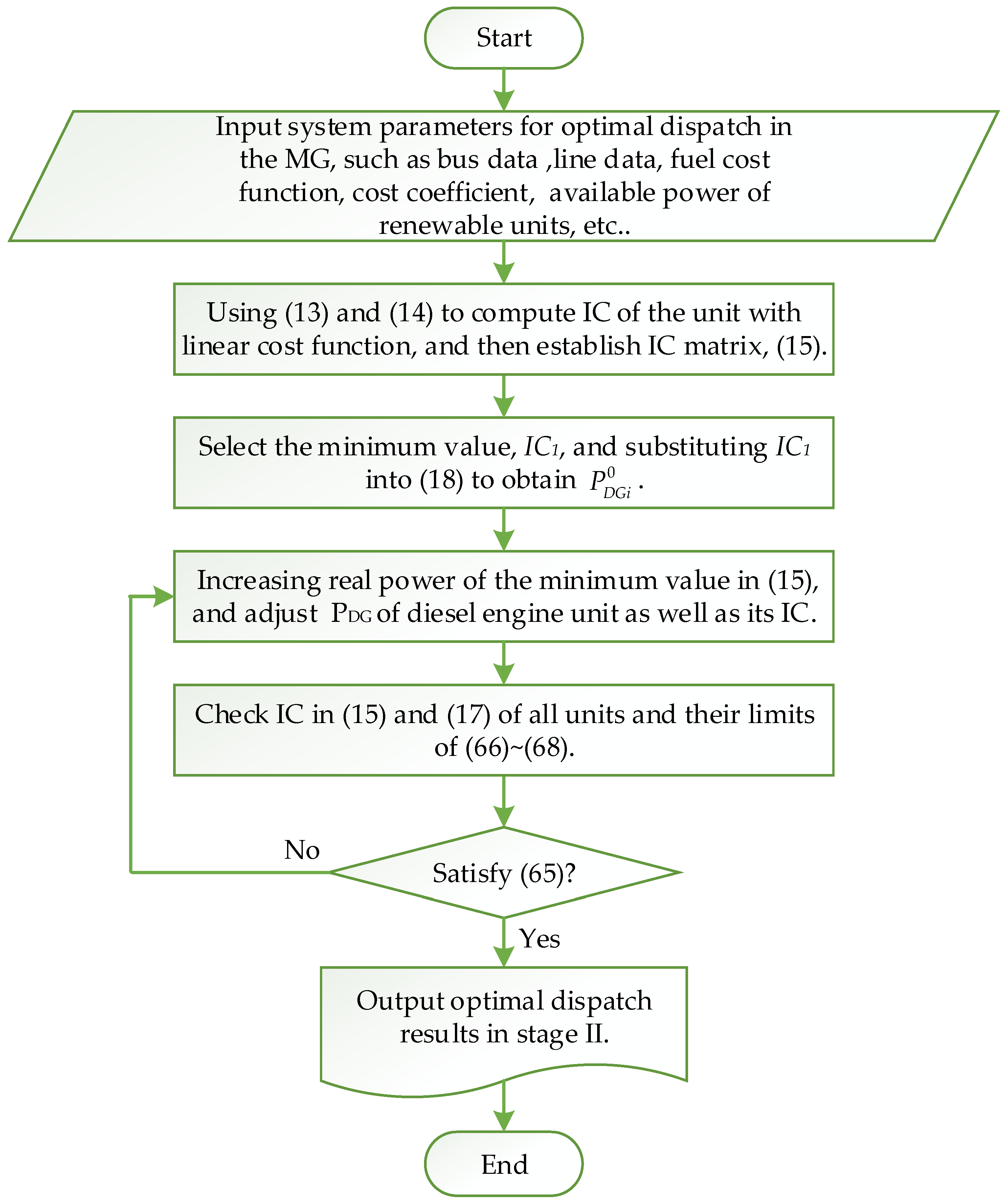
Based on Equations (2) and (7), the model of JBDF-based ED conditions is rewritten as follows:
F i = L P G i = b i + 2 c i P G i + λ ( 1 I T L i ) = 0 ,
F N G + 1 = L λ = i = 1 N G P G i P D P L = 0 ,
extending Equation (48) to all units results in (NG + 1) simultaneous nonlinear equations in a matrix form as follows:
[ 0 F 1 0 F N G + 1 ] = [ J 1 J 2 J 3 J 4 ] [ Δ P G 1 Δ P G N G Δ λ ] ,
Equation (49) can be solved by the Newton-based algorithm, where J1, J2, J3, and J4 are the sub-matrices of Jacobian matrix, as explained in the following section.
The diagonal and off-diagonal elements of J1 are expressed as follows:
F i P G i = 2 c i λ ( I T L i P G i ) = 0 ,
F i P G j = λ ( I T L i P G j ) ,   j i ,
the partial derivatives of ITL are shown in Equations (52) and (53):
I T L i P G i = 2 R m i = 1 N L [ F p 2 ( m , i ) + F q 2 ( m , i ) ] ,
I T L i P G j = 2 R m [ F p ( m , i ) F p ( m , j ) + F q ( m , i ) F q ( m , j ) ] ,   j i ,
the elements of J2 are:
F i λ = 1 I T L i ,
the elements of J3 are:
F N G + 1 P G i = 1 I T L i ,
the elements of J4 are:
F N G + 1 λ = 0 ,
the model of the JBDF-based ED in the main power grid can be derived according to these equations. The solution flow chart is shown in Figure 2. The solution is obtained when the convergence conditions, Δ P and Δ λ , are less than a specified accuracy, i.e., ε . On the contrary, it is divergence, the iterations will reach to maximum iteration number and then stop the iteration procedure. It is worth noting that the Newton-based algorithm is sensitive to the initial guess value. In general, the physical meaning of λ is the system incremental cost of delivered power; therefore, the initial value could be guessed in a reasonable range according to the average cost per megawatt for avoiding the unreasonable solution or divergence.

3.2. Stage II

The DERs are divided into nonrenewable and renewable units. The cost functions of nonrenewable units and the prediction of the available power of renewable units are essential for optimal dispatch in an MG. The characteristics of the DERs are described as follows.
For the nonrenewable units, the fuel cost of a diesel engine generator is expressed as Equation (16), and the total fuel cost of diesel engine units in MG-A are shown in Equation (57). Molten carbonate fuel cells and solid oxide fuel cells are used in this study. The fuel cost of the fuel cell unit is shown in Equation (11), and the total fuel cost of fuel cell units in MG-A is shown in Equation (58). Similar to the cost function of the fuel cell unit, the fuel cost of the fuel cell unit is shown in Equation (12), and the total fuel cost of fuel cell units in MG-A is shown in Equation (59):
F D G ( A ) = i = 1 N D G a D G i + b D G i P D G i + c D G i P D G i 2
F F C ( A ) = i = 1 N F C β i P F C i
F M T ( A ) = i = 1 N M T γ i P M T i
The power output of the wind turbine unit is expressed as Equation (60), where Cp is the power coefficient, ν is the air density, V w is the wind velocity, and A is the rotor swept area. The total power generation of wind power units in MG-A is shown in Equation (61). The power output of the photovoltaic module can be expressed as Equation (62), with the measured solar irradiation (W/m2) and ambient temperature (°C), where Pstc is the maximum power at the standard test condition, Ging is the incident irradiance, Gstc is the irradiance at the standard test condition (1000 W/m2), k is the temperature coefficient of power, Tc is the cell temperature, and Tr is the reference temperature. The total power generation of photovoltaic units in MG-A is shown in Equation (63). Therefore, the renewable units are regarded as negative power loads in optimal dispatch in MGs:
P W T = 1 2 C p ν V w 3 A
P W T ( A ) = 1 2 i = 1 N W T C p i ν V w 3 A
P P V = P S T C G I N G G S T C [ 1 + K i ( T c T r ) ]
P P V ( A ) = i = 1 N P V P P V
On the basis of the cost function and power generation of each unit, we can express the objective function for the optimal dispatch problem in MG-A as follows:
min   F T ( A ) = i = 1 N D G f D G i + i = 1 N F C f F C i + i = 1 N M T f M T i ,
subject to:
i = 1 N D G P D G i + i = 1 N F C P F C i + i = 1 N M T P M T i = Δ P D ( A ) + Δ P L ( A ) Δ P W T ( A ) Δ P P V ( A ) ,
P D G i min P D G i P D G i max ,
P F C i min P F C i P F C i max ,
P M T i min P M T i P M T i max .
Finally, the IDSM is proposed to solve the optimal dispatch in an MG, and the solution flow chart is shown in Figure 3.

3.3. Stage III

In stage III, the linear incremental model of the entire power system is established on the basis of the optimal dispatch solutions of the two previous stages. Considering the power interchange of MG-A, PeA, into the main power grid, we can obtain the linearly optimized model of the main power grid and MG-A. The linearly optimized model in stage III can be derived by increasing N number of MGs in the power system, as shown in Equation (69):
min   J = i = 1 N G Δ f i + j = A N i = 1 N D G Δ f D G ( j , i ) + j = A N i = 1 N F C Δ f F C ( j , i ) + j = A N i = 1 N M T Δ f M T ( j , i )
According to the linear model and satisfying the related constraints, the optimal dispatch generations are solved by linear programming. The optimal solution of the entire power system with MGs as VPPs can also be found.

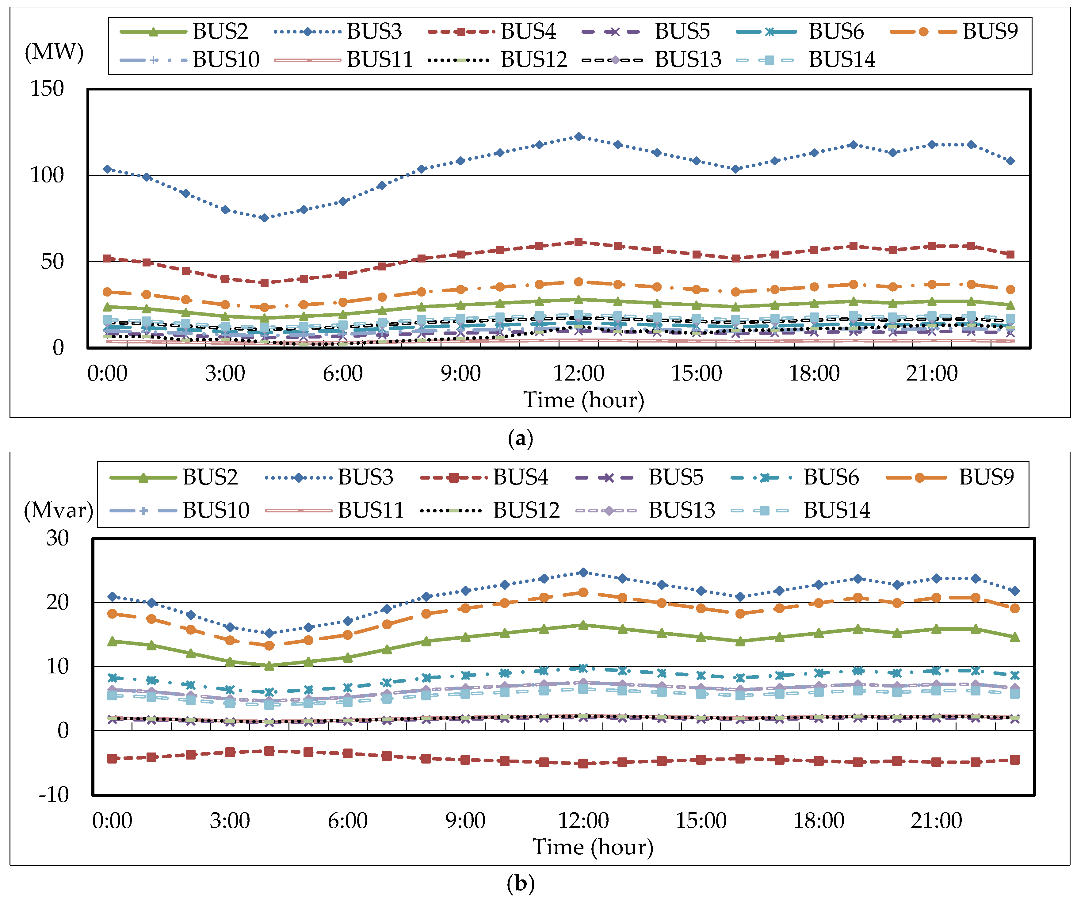
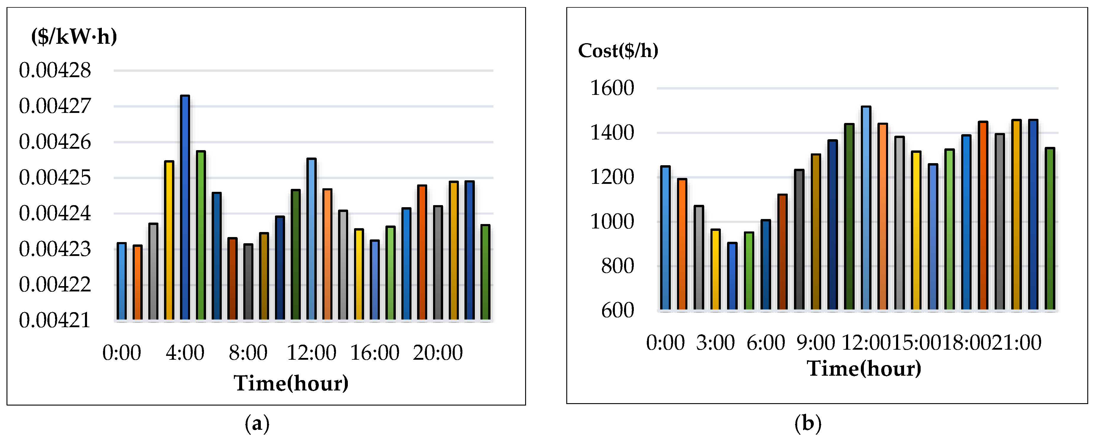
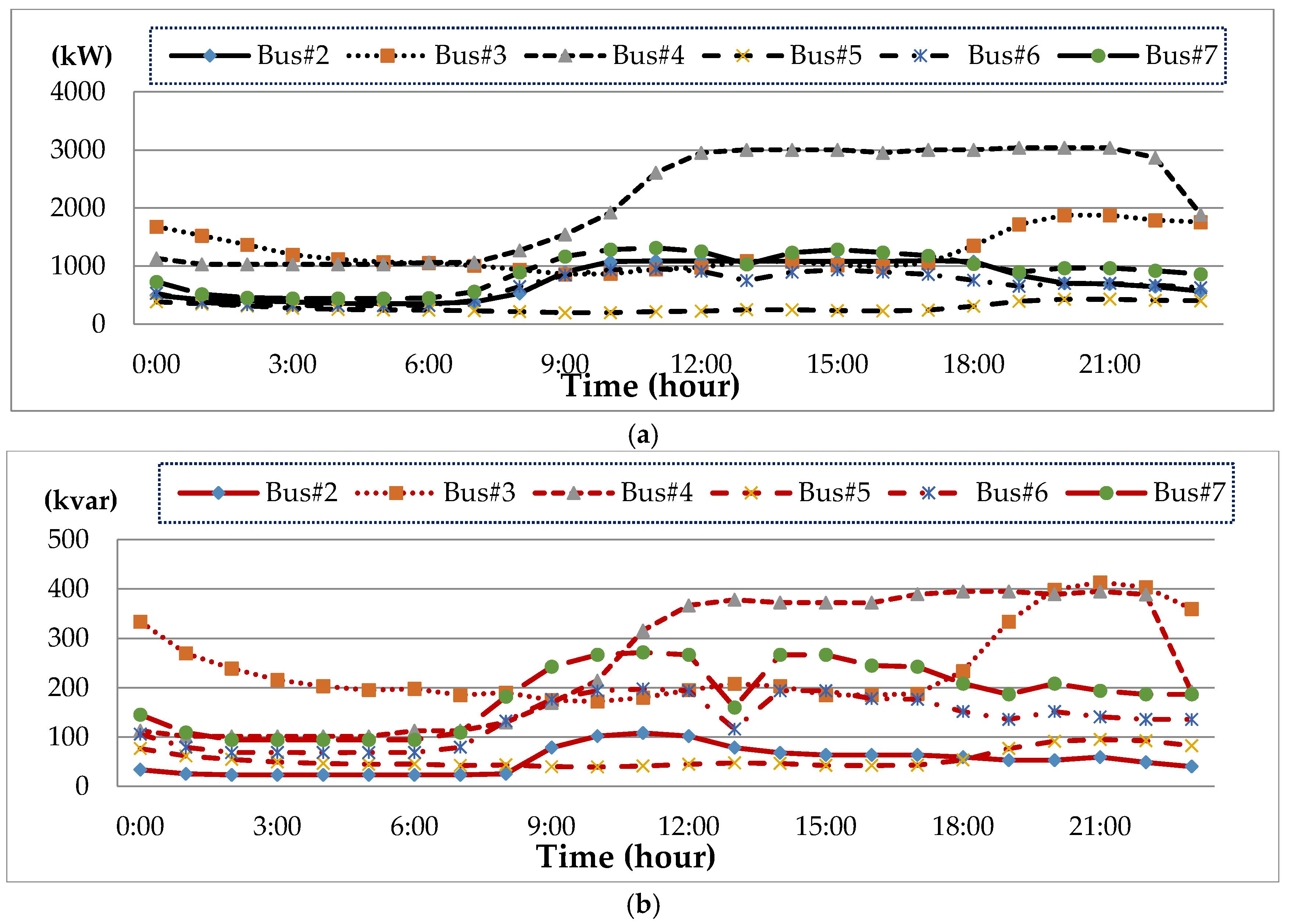
4. Numerical Results and Discussion

An effective ED program is coded in the Matlab environment according to the proposed three-stage model and solution algorithms. The proposed approach is first used to evaluate the ED problem of the original IEEE 14-bus test system and to verify the accuracy and effectiveness of the proposed approach, and the related parameters for power flow and ED are obtained from previous studies [25,26]. In this scenario, the MG is assumed to be operated autonomously and therefore not considered in ED in the main power grid for the comparison of the traditional Lagrange multiplier method and the proposed approach based on the known results. The numerical results (Table 1) demonstrate that the developed ED program is valid. The ED problem of the main power grid considering MGs is then solved by using the three-stage ED program.
The IEEE 14-bus test system and an MG (Figure 4 and Figure 5) are modified as a sample system to verify the feasibility and accuracy of the proposed approach. The equivalent lumped daily load demand curves of the main power grid are illustrated in Figure 6. The equivalent daily load demand curves that correspond to different load types at each bus are shown in Figure 7. The purchased/sold electricity cost of MG-A are depicted in Figure 8. This cost comprises the peak-load (0.2392 $USD/kW·h), half-peak-load (0.0894 $USD/kW·h), and off-peak-load (0.0447 $USD/kW·h) pricing from the main power grid during the summer season. On the basis of the three-stage ED algorithm and constraints, we show the numerical results of the optimal dispatch of each generator in the main power grid in Figure 9, and the optimal power interchange between the main power grid and MG-A is shown in Figure 10. The numerical results of the generation cost per kWh and the total generation cost of the sample system are illustrated in Figure 11a,b, respectively. The numerical results also demonstrate that the bus voltage, current flow, and power generation limits of each unit are consistent with the constraints. The executing time of the proposed approach is around 25% of the traditional Lagrange multiplier method in the IEEE 14-bus test system with a MG; furthermore, there is no divergence problem for power flow solution of the proposed approach because of no iteration after load demand changes. Therefore, the performance of both computation time and reliability of the proposed approach is superior to those of the traditional Lagrange multiplier method. Hence, the proposed approach exhibits high efficiency and rapidly solves the ED of power systems considering MGs as VPPs.

5. Conclusions

In this study, effective and fast three-stage ED model and approach are proposed to solve the problem of modern power systems considering MGs as VPPs. Using the traditional Lagrange multiplier method, we derive the JBDF-based ED algorithm for stage I dispatch according to the network sensitivity factors in the main power grid, and the IDSM for stage II is developed for the optimal dispatch in an MG. The linear incremental model and solution algorithm for stage III are obtained and integrated with stages I and II. For the algorithms proposed in this paper, the power systems are divided into the main power grid and area MGs. The ED problem is solved on the basis of the concept of multi-area ED by using the proposed three-stage approach. Besides, the traditional methods of ED required iterations in each solution procedure; nevertheless the proposed approach only need to execute one iteration procedure by Newton algorithm as base case and then without any iteration after load demand changes. It is absolutely verified that not only the computing speed but also the convergence are superior to other methods that need iterations after load demand changes in real-time dispatch. The numerical results of the test system demonstrate that the proposed approach exhibit high accuracy and efficiency. Therefore, this approach is helpful for optimal dispatch because of the large amounts of DERs interconnected into distribution systems. The proposed approach can also be utilized to solve the area power dispatch problems because of the distribution systems formed as MGs, which are regarded as VPPs for future smart grid applications.

Acknowledgments

The authors are grateful for financial support from the Ministry of Science and Technology, Taiwan, under Grant MOST 105-3113-E-042A-004-CC2.

Author Contributions

The initial idea and formula derivation of the proposed three-stage approach for ED in power system considering MGs was done by Wei-Tzer Huang. The author Kai-Chao Yao evaluated the simulation results and corrected the manuscript. The ED and power flow algorithms were coded by Chun-Ching Wu. The simulation scenarios and results were checked by Yung-Ruei Chang, Yih-Der Lee and Yuan-Hsiang Ho.

Conflicts of Interest

The authors declare no conflict of interest.

References

  1. Milestones: Pearl Street Station. Available online: http://www.ieeeghn.org/wiki/index.php/Milestones:Pearl_Street_Station (accessed on 12 August 2016).
  2. Gomez-Sanz, J.J.; Garcia-Rodriguez, S.; Cuartero-Soler, N.; Hernandez-Callejo, L. Reviewing Microgrids from a Multi-Agent Systems Perspective. Energies 2014, 7, 3355–3382. [Google Scholar] [CrossRef]
  3. Lasseter, R.H. Smart Distribution: Coupled Microgrids. IEEE Power Energy Mag. 2011, 99, 1074–1082. [Google Scholar] [CrossRef]
  4. Smart Grids European Technology Platform. Available online: http://www.smartgrids.eu/ (accessed on 12 August 2016).
  5. Acha, E.; Kazemtabrizi, B. A New STATCOM Model for Power Flows Using the Newton-Raphson Method. IEEE Trans. Power Syst. 2013, 28, 2455–2465. [Google Scholar] [CrossRef]
  6. Chai, R.; Zhang, B.; Dou, J.; Hao, Z.; Zheng, T. Unified Power Flow Algorithm Based on the NR Method for Hybrid ACIDC Grids Incorporating VSCs. IEEE Trans. Power Syst. 2015, 31, 4310–4318. [Google Scholar] [CrossRef]
  7. Kim, S. Accuracy Enhancement of Mixed Power Flow Analysis Using a Modified DC Model. Energies 2016, 9, 776. [Google Scholar] [CrossRef]
  8. Raygani, S.V.; Tahavorgar, A.; Fazel, S.S.; Moaveni, B. Load flow analysis and future development study for an AC electric railway. IET Electr. Syst. Transp. 2012, 2, 139–147. [Google Scholar] [CrossRef]
  9. Soman, S.; Thomas, P.; George, J.; Ganesh, M. Prevention of blackout by an effective forced islanding and restoration scheme. In Proceedings of the 2015 International Conference on Emerging Research in Electronics, Computer Science and Technology (ICERECT), Mandya, India, 17–19 December 2015; pp. 298–303.
  10. Ng, W.Y. Generalized generation distribution factors for power system security evaluations. IEEE Trans. PAS 1981, PAS-100, 1001–1005. [Google Scholar] [CrossRef]
  11. Lin, C.E.; Chen, S.T.; Huang, C.L. A two-step sensitivity approach for real-time line flow calculation. Electr. Power Syst. Res. 1991, 21, 63–69. [Google Scholar] [CrossRef]
  12. Huang, W.T.; Yao, K.C. New Network Sensitivity-Based Approach for Real-Time Complex Power Flow Calculation. IET Gener. Transm. Distrib. 2012, 6, 109–120. [Google Scholar] [CrossRef]
  13. Sun, B.; Luh, P.B.; Jia, Q.S.; Yan, B. Event-Based Optimization within the Lagrangian Relaxation Framework for Energy Savings in HVAC Systems. IEEE Trans. Autom. Sci. Eng. 2015, 12, 1396–1406. [Google Scholar] [CrossRef]
  14. Guo, Y.; Wu, W.; Zhang, B.; Sun, H. A Fast Solution for the Lagrange Multiplier-Based Electric Power Network Parameter Error Identification Model. Energies 2014, 7, 1288–1299. [Google Scholar] [CrossRef]
  15. Marlon, C.; Osvaldo, A. Economic Dispatch of Energy and Reserve in Competitive Markets Using Meta-heuristic Algorithms. IEEE Latin Am. Trans. 2013, 11, 473–478. [Google Scholar]
  16. Soroudi, A.; Rabiee, A. Optimal multi-area generation schedule considering renewable resources mix: A real-time approach. IET Gener. Transm. Distrib. 2013, 7, 1011–1026. [Google Scholar] [CrossRef]
  17. Niu, Q.; Zhou, Z.; Zhang, H.-Y.; Deng, J. An Improved Quantum-Behaved Particle Swarm Optimization Method for Economic Dispatch Problems with Multiple Fuel Options and Valve-Points Effects. Energies 2012, 5, 3655–3673. [Google Scholar] [CrossRef]
  18. Sun, J.; Xu, W.B.; Feng, B. A Global Search Strategy of Quantum-Behaved Particle Swarm Optimization. In Proceedings of the IEEE Conference on Cybernetics and Intelligent Systems, Singapore, 1–3 December 2004; pp. 111–116.
  19. Cheng, W.; Zhang, H. A Dynamic Economic Dispatch Model Incorporating Wind Power Based on Chance Constrained Programming. Energies 2015, 8, 233–256. [Google Scholar] [CrossRef]
  20. Li, Z.; Wu, W.; Zhang, B.; Sun, H.; Guo, Q. Dynamic Economic Dispatch Using Lagrangian Relaxation With Multiplier Updates Based on a Quasi-Newton Method. IEEE Trans. Power Syst. 2013, 28, 4516–4527. [Google Scholar] [CrossRef]
  21. Zaman, M.F.; Elsayed, S.M.; Ray, T.; Sarker, R.A. Evolutionary Algorithms for Dynamic Economic Dispatch Problems. IEEE Trans. Power Syst. 2016, 31, 1486–1495. [Google Scholar] [CrossRef]
  22. Liu, Y.; Huang, G.; Cai, Y.; Dong, C. An Inexact Mix-Integer Two-Stage Linear Programming Model for Supporting the Management of a Low-Carbon Energy System in China. Energies 2011, 4, 1657–1686. [Google Scholar] [CrossRef]
  23. Bai, H.; Miao, S.; Ran, X.; Ye, C. Optimal Dispatch Strategy of a Virtual Power Plant Containing Battery Switch Stations in a Unified Electricity Market. Energies 2015, 8, 2268–2289. [Google Scholar] [CrossRef]
  24. Wood, A.J.; Wollenberg, B.F. Power Generation, Operation and Control, 2nd ed.; John Wiley: New York, NY, USA, 2007. [Google Scholar]
  25. Huang, W.-T.; Yao, K.-C.; Wu, C.-C. Using the Direct Search Method for Optimal Dispatch of Distributed Generation in a Medium-Voltage Microgrid. Energies 2014, 7, 8355–8373. [Google Scholar] [CrossRef]
  26. Power Systems Test Case Archive. Available online: http://www.ee.washington.edu/research/pstca/ (accessed on 12 August 2016).
Figure 1. Structure of a power system considering N distribution substation-level MGs.
Energies 09 00976 g001
Figure 2. Solution flow chart of the JBDF-based ED in the main power grid.
Energies 09 00976 g002
Figure 3. Solution flow chart of IDSM in an MG.
Energies 09 00976 g003
Figure 4. IEEE 14-bus test system with MG-A.
Energies 09 00976 g004
Figure 5. MG-A connected at bus 12.
Energies 09 00976 g005
Figure 6. Daily load curve of the IEEE 14-bus test system, (a) real power; (b) reactive power.
Energies 09 00976 g006
Figure 7. Daily load curve of MG-A, (a) real power; (b) reactive power.
Energies 09 00976 g007
Figure 8. Electricity purchased/sold cost of MG-A.
Energies 09 00976 g008
Figure 9. Numerical results for the optimal generation of each unit in the main power grid.
Energies 09 00976 g009
Figure 10. Power interchange between the main power grid and MG-A.
Energies 09 00976 g010
Figure 11. Numerical results of the generation cost per kWh and total generation cost. (a) generation cost per kW-hour; (b) total generation cost.
Energies 09 00976 g011
Table 1. Comparison of the simulation results of the traditional Lagrange multiplier method and the proposed approach for the ED of the original IEEE 14-bus test system.
Bus No.Traditional Lagrange Multiplier (A)Proposed Approach (B)Error %
Generation (MW)Generation (MW)|1 − B/A| × 100
1160.450160.4600.0062
268.80368.8100.0102
639.56739.5500.0430
Total cost ($/h)1137.71137.70.0000
Real power loss (MW)9.829.820.0000
λ405.4473405.45900.0029
CPU execution time (s)0.1880.047-

