Article

Parameter Sensitivity Analysis for Fractional-Order Modeling of Lithium-Ion Batteries

1
School of Astronautics, Northwestern Polytechnical University, Xi’an 710072, China
2
Institut de recherche sur les transports l'énergie et la société (IRTES), Fédération de recherche FCLAB CNRS 3539, Université de Technologie de Belfort-Montbéliard, Belfort 90010, France
*
Author to whom correspondence should be addressed.
Energies 2016, 9(3), 123; https://doi.org/10.3390/en9030123
Submission received: 18 December 2015 / Revised: 27 January 2016 / Accepted: 3 February 2016 / Published: 24 February 2016

Abstract

:
This paper presents a novel-fractional-order lithium-ion battery model that is suitable for use in embedded applications. The proposed model uses fractional calculus with an improved Oustaloup approximation method to describe all the internal battery dynamic behaviors. The fractional-order model parameters, such as equivalent circuit component coefficients and fractional-order values, are identified by a genetic algorithm. A modeling parameters sensitivity study using the statistical Multi-Parameter Sensitivity Analysis (MPSA) method is then performed and discussed in detail. Through the analysis, the dynamic effects of parameters on the model output performance are obtained. It has been found out from the analysis that the fractional-order values and their corresponding internal dynamics have different degrees of impact on model outputs. Thus, they are considered as crucial parameters to accurately describe a battery’s dynamic voltage responses. To experimentally verify the accuracy of developed fractional-order model and evaluate its performance, the experimental tests are conducted with a hybrid pulse test and a dynamic stress test (DST) on two different types of lithium-ion batteries. The results demonstrate the accuracy and usefulness of the proposed fractional-order model on battery dynamic behavior prediction.

1. Introduction

Nowadays, electric vehicles (EVs), including hybrid electric vehicles (HEVs) and fuel-cell-based HEVs (FCHEV), are considered to be an effective way to achieve significant fuel consumption and carbon emission reductions [1]. Compared with fuel cells [2,3], lithium-ion batteries are considered the principal candidate for short- and medium-range EVs due to their advantages of high energy density, longer cycle life, easier management, safer chemistry and broad operation temperature range. To ensure reliable and safe operation, a battery management system (BMS) is necessary for the lithium-ion battery packs in EVs [4,5]. An important requirement for the BMS is that it should be able to provide an accurate estimation of state of charge (SOC) and state of health (SOH) for the battery. In general, designing an accurate BMS estimation algorithm for SOC and SOH requires a battery model that can accurately describe the battery terminal voltage behaviors in both steady-state and dynamic transient conditions.
Generally speaking, battery models presented in literature can be divided in two categories: (1) equivalent-circuit models (ECMs), and (2) physics-based electrochemical models. ECMs use equivalent voltage sources, resistors and capacitors to characterize the battery output voltage feature. Due to their mathematical simplicity and acceptable precision, ECMs are widely used in BMS for online embedded applications. However, ECMs ignore various electrochemical processes inside the battery, and the model parameter identification might be biased by measurement disturbances. Consequently, the prediction error of ECMs could be very high, especially in the low SOC range [6]. In [7], several lumped equivalent-circuit models have been proposed to approximate the battery behaviors including open-circuit voltage, Ohmic loss, polarization time constants and electro-chemical hysteresis. A comparative study of the accuracy of several lumped equivalent-circuit models which included the hysteresis, enhanced self-correcting, first-order RC, second-order RC, and third-order RC models, was given in [8].
Alternately, physics-based electrochemical battery models can achieve high precision, because they use partial differential equations (PDEs) to describe the exact electrochemical behavior inside the battery. In [9] a pseudo-two-dimensional model was developed. The model illustrates the internal electrochemical dynamic behaviors, such as the mass/charge transfer processes, ionic conduction and solid phase diffusion. A one dimensional physics-based electrochemical model has been proposed in [10], which uses discrete time state space representation to describe the internal lithium-ion transport phenomena. However, physics-based models cannot be directly used in BMS for online applications due to their high computational demand for solving physics-based differential equation systems [11,12]. The choice of battery model should be determined by the field of application, as investigated in [13], because different applications have different accuracy requirements and real-time criteria. Thus, the proper selection of a battery model for online implementation has to be a compromise between modeling accuracy and solving speed.
In our previous work [14,15], a SOC estimation algorithm based on multi-model data fusion was proposed for real-time applications. The experimental results showed that the proposed algorithm can simultaneously maintain accuracy and relatively fast computation for real-time applications. However, the multiple models including ECM and physics-based extended single particle models used in [14,15] are conventional models, so they have the abovementioned drawbacks.
One effective modeling solution to overcome the computational problem of complex models while maintaining high modeling accuracy is to use fractional calculus, which is an expansion of classic integer-order calculus to fractional-order. Fractional-order models can accurately predict dynamic behaviors by using much less computational resources compared to classic complex electrochemical equation-based models. Indeed, many phenomena in electrochemistry often demonstrate fractional-order dynamics rather than integer-order dynamics [16]. In addition, fractional calculus can effectively introduce additional degrees of freedom for model parameter identification. Thus, the use of fractional calculus can provide a more accurate description of the dynamic behaviors for lithium-ion batteries. Different approaches for lithium-ion battery fractional-order models can be found in the literature. Zhong et al. [17] have proposed a Riemann–Liouville definition-based fractional-order equivalent circuit model, and accurate SOC estimation results are obtained using an adaptive sliding mode observer. Cugnet et al. [18] have presented a fractional-order model to characterize the lead-acid battery behavior during vehicle cranking. From their model, the battery resistance power and cranking capability can be evaluated with precision. Alavi et al. [19] have introduced a fractional-order electrochemical impedance model for lithium-ion batteries. In their model, the fractional-order parameters are identified by a combination of a simplified refined instrumental variable algorithm and a gradient-based optimization method. Wu et al. [20] have done several experimental tests in order to identify different parameters of the developed fractional-order model for lithium-ion batteries. Sabatier et al. [21] have proposed another fractional electrochemical model for lithium-ion batteries. The resolution of PDEs and internal lithium-ion transport phenomena are described in fractional form and fractional transfer function, respectively.
Indeed, during lithium-ion battery operation, there are various electrochemical phenomena occurring in both electrodes and separator. However, the abovementioned fractional equivalent circuit models in the literature only consider part of the dynamic behavior, and other dynamics such as lithium-ion migration and diffusion processes are not included. For the fractional electrochemical model, large computations and memories are needed due to its complex electrochemical PDEs, thus it cannot be directly used in BMS for real-time applications. In addition, most fractional calculus approaches used in these fractional models are complex and non-recursive, which leads to a heavy computational burden. Furthermore, a common negligence of these fractional models in the literature is that, the influence of the parameters, especially the effect of the values of fractional calculus on the battery model performance, has never been analyzed or discussed for the battery model development. In fact, by definition, the fractional-order model can show various voltage dynamic characteristics by changing the values of fractional-order parameters. Thus, the lack of knowledge about the sensitivity and dynamic effect of each fractional-order parameter can lead to an inaccurate fractional-order model output result.
In this paper, a novel-fractional-order model for lithium-ion batteries is presented at first. The proposed fractional-order model can accurately describe all the lithium-ion battery internal electrochemical behaviors, including battery Ohmic losses, lithium-ion migration through the solid electrolyte interface (SEI) layer, charge transfer kinetics, double layer effects, and lithium-ion diffusion processes using free fractional-orders elements. The proposed fractional-order model is developed and solved using an improved Oustaloup approximation algorithm [22,23], which can recursively approximate free fractional-orders transfer function from a set of integer-order filters for lithium-ion battery models. For the parameter identification process of the proposed model, a genetic algorithm is used. Secondly, a full analysis of modeling parameter sensitivity, including circuit components coefficients and fractional-order values, is performed. The experimental validation of the proposed model is then performed on two different types of lithium-ion batteries. In order to highlight the usefulness of the developed model, a comparison between the prediction results of the proposed fractional-order model and a classic second-RC model is also presented. Experimental results show that, the proposed fractional-order battery model can accurately describe the battery terminal voltage with dynamic transient behaviors. In addition, the parameter sensitivities analyses provide insights into the influence of fractional-order parameters, which is important for accurate description of dynamic behaviors of battery model. The novel contributions of this paper can be summarized as follows:
  • All the battery internal dynamic behaviors, including SEI layer, charge transfer kinetics, double layer effects, and lithium-ion diffusion processes are accurately captured by simple free fractional-orders elements in the proposed model. With the proposed model, the battery voltage dynamics of charging and discharging can be precisely reproduced without using complex electrochemical equations. Thus, the proposed model can accurately predict dynamic behaviors inside the battery by using much less computational resources compared to classic electrochemical equations-based models. This feature makes the proposed model particularly suitable for implementation in real time embedded applications.
  • The presented new fractional calculus method solves the boundary fitting problems using the innovative improved Oustaloup recursive algorithm, which, to the best of our knowledge, has never been used for lithium-ion battery models in the literature. This novel approach combines a boundary fitting optimization algorithm with a traditional Oustaloup recursive approximation method, thus the calculation accuracy and efficiency are both satisfied. In this case, a satisfactory fitting result can be efficiently achieved in the whole pre-specified frequency range. Compared to other fractional calculus approximation algorithms, the proposed efficient approach in this paper provides a more precise approximation of free fractional-orders derivative by a series of integer-order filters. From our point of view, this approach is a novel contribution in approximating lithium-ion battery free fractional-order models.
  • The modeling parameter sensitivities, especially the effect of the values of fractional calculus on the battery model performance, are analyzed in this paper. This analysis provides insights into the influence of fractional-order parameters, and further shows which internal dynamic behaviors have more significant effects on battery terminal voltage.

2. Fractional-Order Models

In order to have a general understanding of fractional-order system, more definitions of fractional calculus are given in the Appendix A. In this section, the proposed novel fractional-order lithium-ion battery model is presented based on the battery electrochemical impedances approach [19]. The mathematical modelling equations and the fractional transfer functions are described and solved using an improved fractional-order system approximation method [22,23]. Finally, the parameters identification process is shown as well.

2.1. An Improved Oustaloup Recursive Approximation Algorithm

The numerical integer-order approach of derivation for fractional transfer functions is critical in fractional-order systems. As an efficient approach, the Oustaloup recursive approximation algorithm [22] is widely used to approximate fractional-order transfer functions, and hence selected in this paper. The Oustaloup algorithm uses a set of integer-order filters for approximation of free fractional-order derivatives in a certain frequency range. However, it has been indicated that, in the Oustaloup algorithm, the numerical fitting accuracy is not satisfactory in the regions near the lower bound ω a and upper bound ω b .
To overcome this boundary fitting drawback of the Oustaloup algorithm, an improved filter design is proposed in [23], which combines a boundary fitting optimization algorithm with traditional Oustaloup recursive approximation method, thus maintain simultaneously the calculation accuracy and efficiency.
In this paper, the notation s in Laplace domain is used to describe fractional differentiation:
L { D α f ( t ) } =   s α F ( s ) ( 0 < α 1 )
Then the general single-input single-output (SISO) system can be expressed in a fractional-order transfer function form:
G ( s ) = Y ( s ) U ( s ) = μ 0 s α 0 + μ 1 s α 1 + + μ m s α m ν 0 s β 1 + ν 1 s β 2 + + ν n s β n
where μ 0 , μ 1 , , μ m and ν 0 , ν 1 , , ν n are system parameters, α 0 < α 1 < < α m and β 1 < β 2 < < β n are the fractional orders, which are all real numbers.
Based on the first-order approximation of Taylor series expansion of Equation (A23) in Appendix A, the improved filter is thus given by:
s α = ( d ω h b ) α ( d s 2 + b ω h s d ( 1 α ) s 2 + b ω h + d α ) k = N N 1 + s ω k * 1 + s ω k
A more detailed derivation can be found in Appendix A. In this paper, this improved Oustaloup approximation is applied to the fractional-order transfer functions of the proposed lithium-ion battery model.

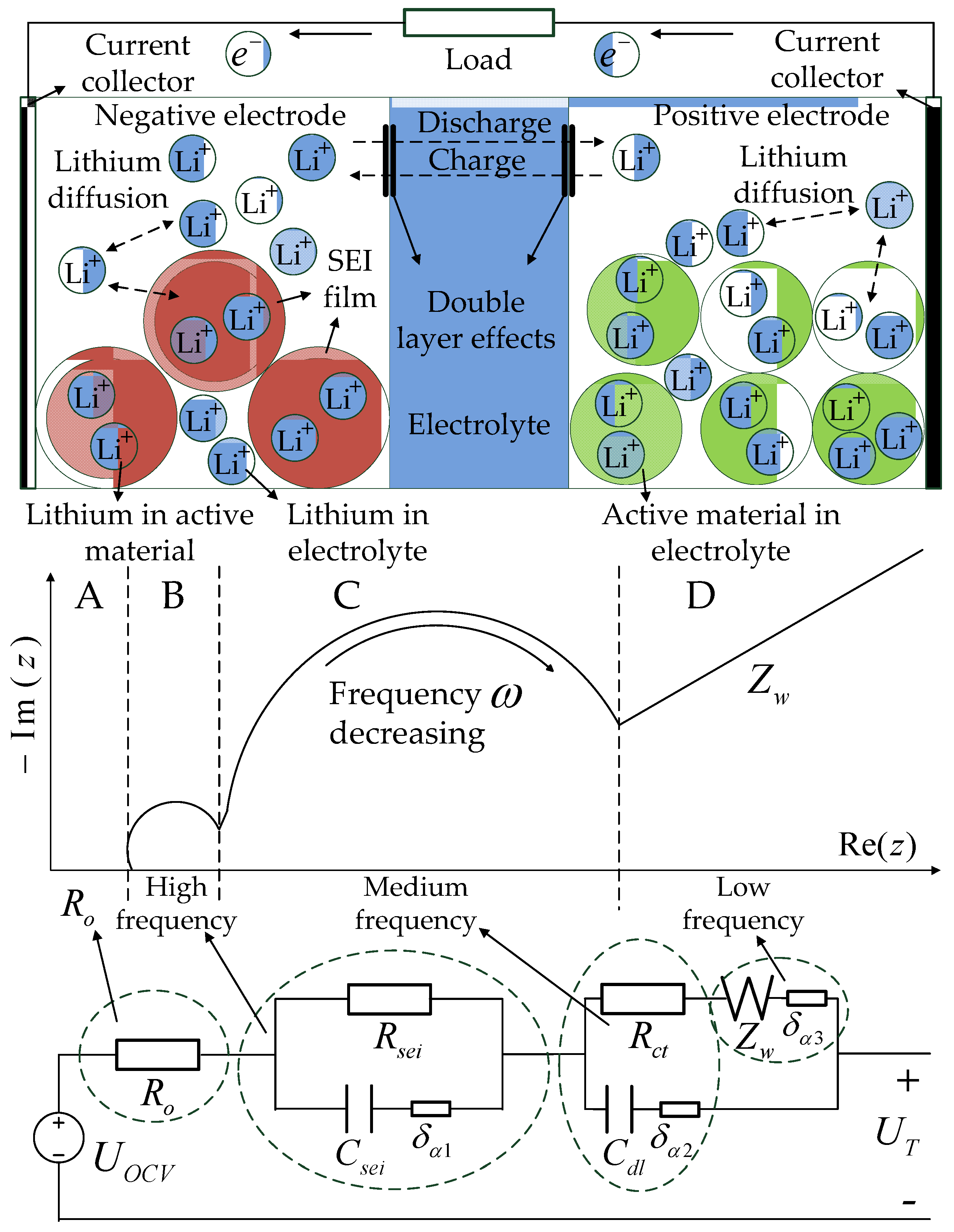
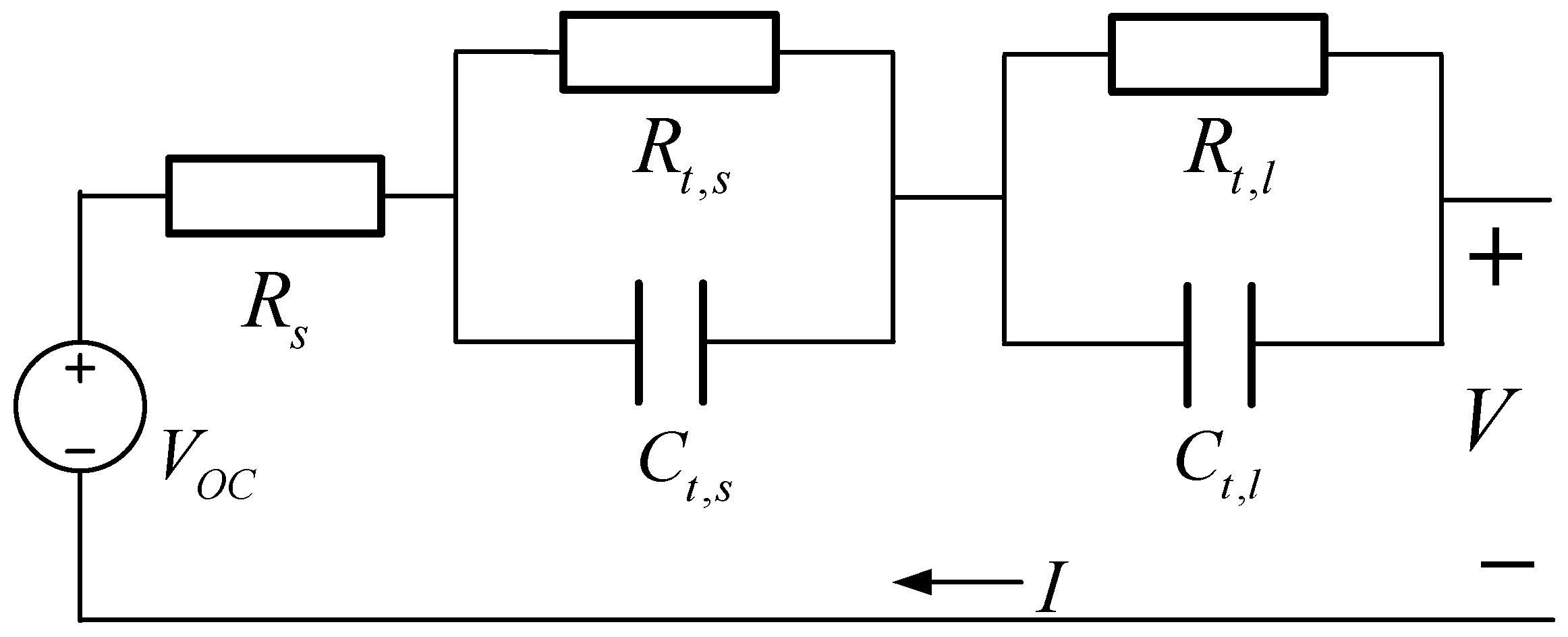
2.2. Structure of Equivalent Fractional-Order Electrochemical Impedance Model

The fractional-order electrochemical impedance modeling approach of a lithium-ion battery consists of different dynamic phenomena inside the battery: lithium-ion migration through the solid electrolyte interface (SEI) layer, activation kinetics in both negative and positive electrodes, double layer effects at the interfaces of electrolytes, and lithium-ion diffusion processes in the active material of the electrodes. In order to characterize these phenomena, the electrochemical impedance spectroscopy (EIS) method is generally used. The lithium-ion battery internal dynamics phenomena, the corresponding EIS Nyquist diagram and the proposed equivalent fractional-order impedance circuit diagram are shown in Figure 1.
It can be seen from the Figure 1 that, the EIS Nyquist diagram can be divided into four regions [24,25,26]:
  • Region A can be represented by a single Ohmic resistance R o , this area corresponds to battery Ohmic losses, including the resistances of current collectors, active material, electrolyte and separator.
  • High frequency region B, which can be represented by a solid electrolyte interface (SEI) resistance R s e i , a SEI layer capacitance C s e i , and a fractional element δ α 1 , corresponds to the lithium-ion migration through the SEI film layer.
  • Medium frequency region C, which can be represented by a charge transfer resistance R c t , a double layer capacitance C d l , and a fractional element δ α 2 , corresponds to the activation kinetics and double layer effects at the interface of electrolytes;
  • Low frequency region D, which can be represented by a Warburg element Z w and a fractional element δ α 3 , corresponds to lithium-ion diffusion processes in the active material of the electrodes.
Based on the analysis above, each region in the battery EIS Nyquist diagram can be represented by an equivalent fractional-order circuit unit, and each circuit unit contributes to the Nyquist curve shape as indicated by the arrows.

2.3. Mathematical Description of Fractional-Order Model

The open circuit voltage U o c v of the battery, which is a function of battery state-of-charge ( S O C ) [14,15], is given by:
U o c v ( t ) = K 0 + K 1 l n [ S O C ( t ) ] + K 2 l n [ 1 S O C ( t ) ] + s ( t ) M
where K 0 , K 1 , K 2 , M are coefficients to be identified, and s represents the sign of current described as follow:
s ( t ) = { 1 ,   I L ( t ) > ε 1 , I L ( t ) < ε   s ( t 1 ) , | I L ( t ) | ε  
where ε is a small positive number.
The SOC represented as the ratio of the remaining capacity to the fully charged nominal capacity of the battery, is given by:
S O C ( t ) = S O C ( 0 ) + 0 t η I L ( τ ) C n d τ
where S O C ( 0 ) represents the initial state of charge, C n represents the battery cell nominal capacity in Ampere hour, η is the coulomb efficiency, I L is the battery current (positive for discharging, negative for charging).
Thus, from Figure 1, the corresponding fractional-order differential equation for each equivalent electrical component can be expressed by:
{ D α 1 U sei = 1 R sei C sei U sei + 1 C sei I L D α 2 U ct = 1 R ct C dl ( U ct U w )+ 1 C sei I L D α 3 U w = 1 R ct W d ( U ct U w ) U T = U ocv U sei U ct R o I L
where D α denotes α order of fractional derivative ( 0 α 1 ), U s e i , U c t and U w represents the voltage across equivalent resistance R s e i , R c t and Warburg element Z w respectively. α 1 , α 2 and α 3 are values of fractional derivative, W d is the coefficient of Warburg element, and U T is the terminal voltage. Thus the relationship between U T , U o c v can be expressed by:
U T = U o c v U F  
where U F is the voltage across the components including R o , R s e i  and  R c t . Thus, the total battery electrochemical impedance can be expressed as follow:
Z U ocv U T ( jω )= R o + R sei R sei C sei ( jω ) α 1 +1 + R ct W d ( jω ) α 3 +1 R ct C dl ( jω ) α 2 W d ( jω ) α 3 + C dl ( jω ) α 2 + W d ( jω ) α 3
From Equation (9), the fractional-order transfer function in Laplace domain can be given by Equation (10). The integer-order approximation approach of fractional calculus (3) can be then applied to the obtained fractional-order transfer function (10).
G U ocv U T ( s )= U ocv ( s ) U T ( s ) I L ( s ) = μ 0 s α 1 + α 2 + α 3 + μ 1 s α 1 + α 2 + μ 2 s α 1 + α 3 + μ 3 s α 2 + α 3 + μ 4 s α 1 + μ 5 s α 2 + μ 6 s α 3 +1 ν 0 s α 1 + α 2 + α 3 + ν 1 s α 1 + α 2 + ν 2 s α 1 + α 3 + ν 3 s α 2 + α 3 + ν 4 s α 2 + ν 5 s α 3 [ μ 0 , μ 1 , μ 2 , μ 3 , μ 4 , μ 5 , μ 6 ] =[ R 0 R sei R ct C sei C dl W d , R 0 C sei C dl ,( R sei R ct + R 0 ) C sei W d ,2 R sei R ct C dl ( R sei +1 ), W d ( R sei +1 ) ] [ ν 0 , ν 1 , ν 2 , ν 3 , ν 4 , ν 5 ]=[ R sei R ct C sei C dl W d , C sei C dl , C sei W d , R ct C dl W d , C dl , W d ]

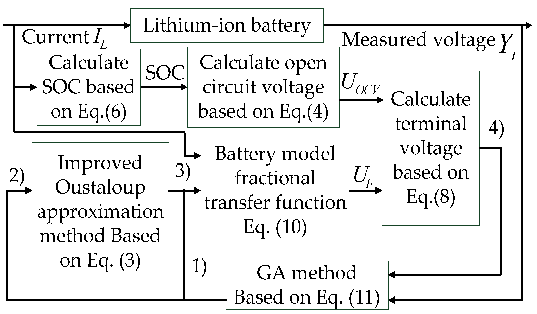
2.4. Model Parameters Identification Method

As a commonly used strategy of parameter identification, the recursive least squares method is well-suited for general ECM [14]. For the proposed fractional-order model identification, genetic algorithm (GA) is particularly useful for such multi-parametric and nonlinear system estimation [27]. The purpose of GA is to find optimal solution for objective function f ( χ ^ i g ) as follows:
f ( χ ^ t g ) = m i n { t = T 0 T [ ( Y t Y ^ ( χ ^ t g ) ] 2 }
where χ ^ t g is the estimated parameter values at time t for the generation g , Y t is the measured output value at time t , and Y ^ ( χ ^ t g ) is the predicted output value.
The parameters identification framework design for the proposed model is shown in Figure 2.
The parameters need to be estimated are given by:
θ = [ R o , R s e i , R c t , C s e i , C d l , W d , α 1 , α 2 , α 3 ]
The detailed steps of Algorithm (1)–(4) are expressed as follows:
  • Initialize the original generation parameters θ within the given parameters variation range, which are achieved using recursive least squares [28]. Then the lumped parameters μ = [ μ 0 , μ 1 , μ 2 , μ 3 , μ 4 , μ 5 , μ 6 ] and ν = [ ν 0 , ν 1 , ν 2 , ν 3 , ν 4 , ν 5 ] are generated for the fractional-order transfer function (10).
  • Fractional order value α = [ α 1 , α 2 , α 3 ] is used for calculating the fractional derivative s α using improved Oustaloup approximation Algorithm (3), where b = 9 and d = 10 [23].
  • The detailed expression of fractional transfer function can be obtained by μ , ν and s α . Meanwhile, battery current I L is defined as the input of fractional transfer function, to calculate the output voltage U F of the transfer function.
  • The predicted terminal voltage Y ^ ( χ ^ t g ) can be obtained using (8), then the fitness value can be obtained from estimation error Y t Y ^ ( χ ^ t g ) . Based on the fitness value, GA will take a series of actions, including elitism selection, crossover and mutation, and output the new individual parameters for next estimation iteration.

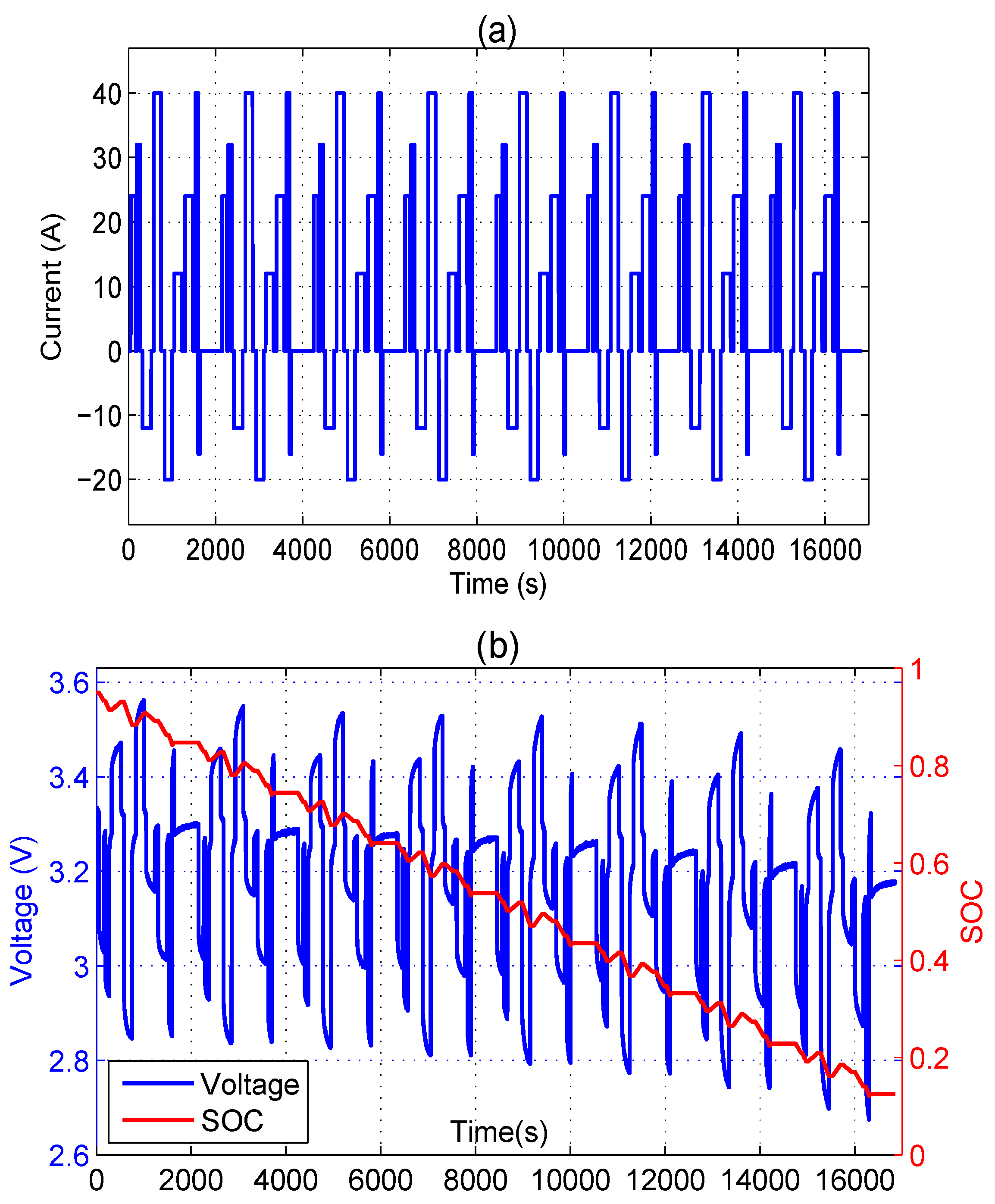
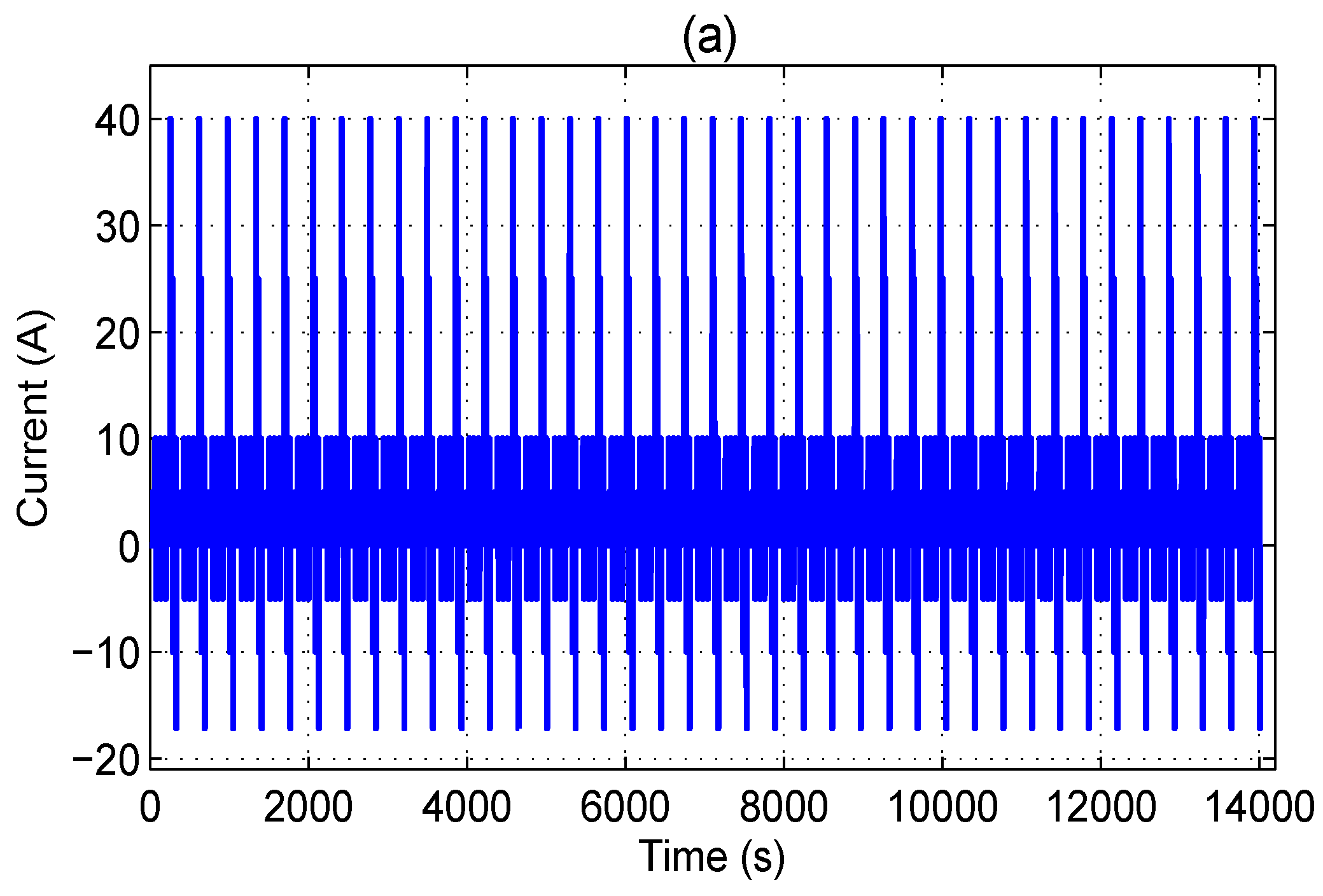
3. Experimental Validation of the Fractional-Order Model

The fractional-order battery modelling technique and the GA-based identification method are applied to real applications, and the experimental results and analyses are performed in this section.

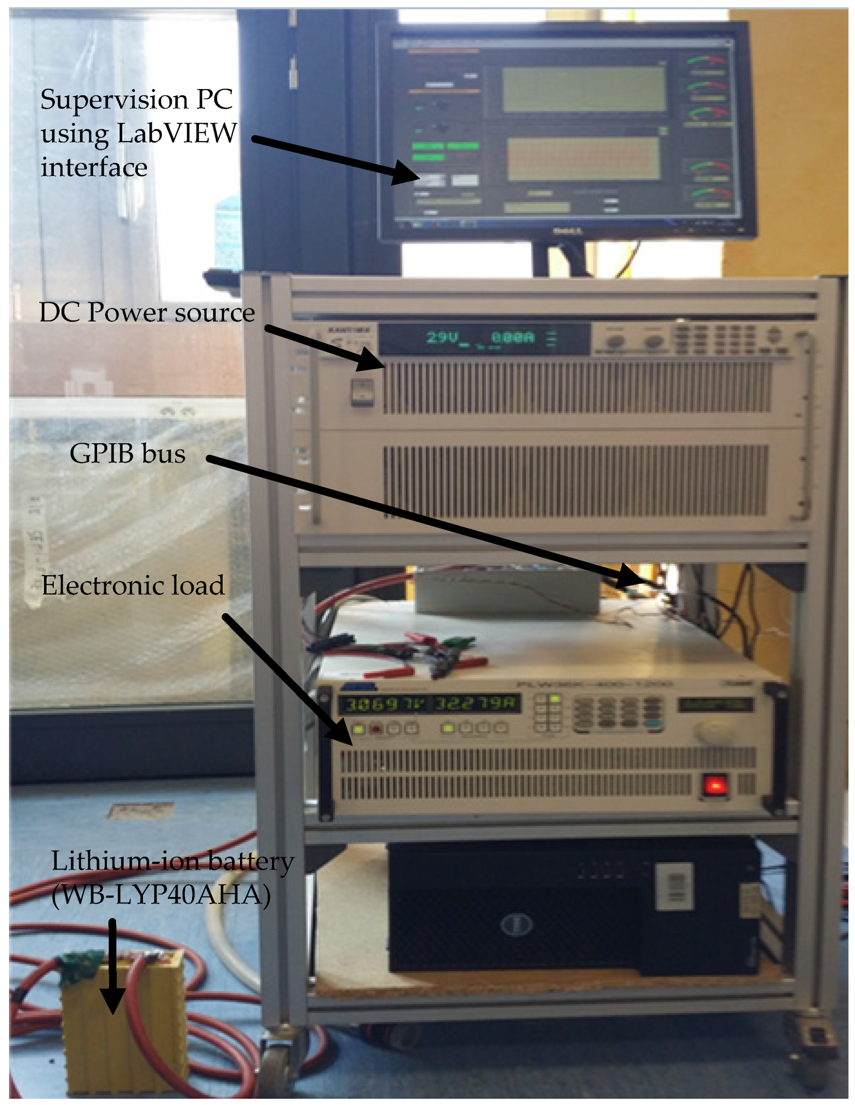
3.1. Experiment Setup

In order to experimentally validate the developed fraction-order lithium-ion battery model, two types of lithium-ion cells were used in our experimental tests. The first cell is a rare earth lithium yttrium battery (WB-LYP40AHA) manufactured by the Winston Company (Shenzhen, China), the second one is a lithium-ion phosphate battery (LiFePO4) manufactured by the Tenergy Company (Fremont, CA, USA). The experimental platform is developed as shown in Figure 3, and the main parameters of the two batteries are listed in Table 1. In the experimental setup, the battery cell is only connected to a programmable DC power supply and an electronic load. The power supply and electronic load are used to perform the battery charging and discharging cycles at the desired rates, respectively. Both charging and discharging cycles signals are generated by a PC using the LabVIEW software (National Instrument, Austin, TX, USA) and sent to power components via digital interfaces (GPIB and RS232). All the battery terminal voltage and current measurements from the different sensors were centralized, treated and stored in the supervising PC.
In order to verify the validity of the proposed model and to evaluate its performance, experiments are conducted with a hybrid pulse test and a dynamic stress test (DST) [29]. As shown in Figure 4, the hybrid pulse test is a sequence of pulse cycles including standard Hybrid Pulse Power Characterization (HPPC) profile and a custom-defined discharging/charging pulse profile [29]. The purpose of hybrid pulse test is to provide battery dynamic datasets for all SOC range for parameters identification. On the other hand, DST simulates the driving cycle-based conditions, and aims to evaluate the proposed model performance as shown in Figure 5.

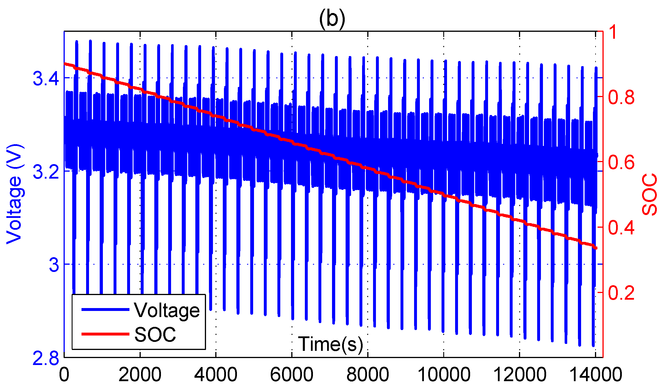
3.2. Identification Results

The parameters estimation process (Figure 2) have been performed with the recorded datasets of the hybrid pulse test (Figure 4). A number of generations g = 200 is selected to achieve the optimal solution for objective function f ( χ ^ i g ) . The pre-computed coefficients K 0 , K 1 , K 2 , M are used in Equation (4) based on a previous work presented in [14,15]. The identified model parameters are given in Table 2. In order to validate the identification results with the proposed model, the measured voltages of hybrid pulse test on two type batteries are compared with the fractional-order model output voltages in Figure 6.
From Figure 6, it can be seen that the model prediction is very close to the experimental measurement over the entire SOC range.

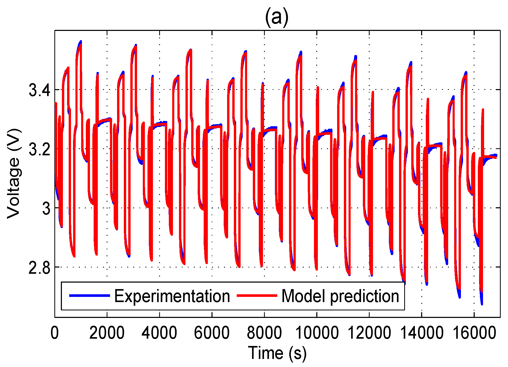
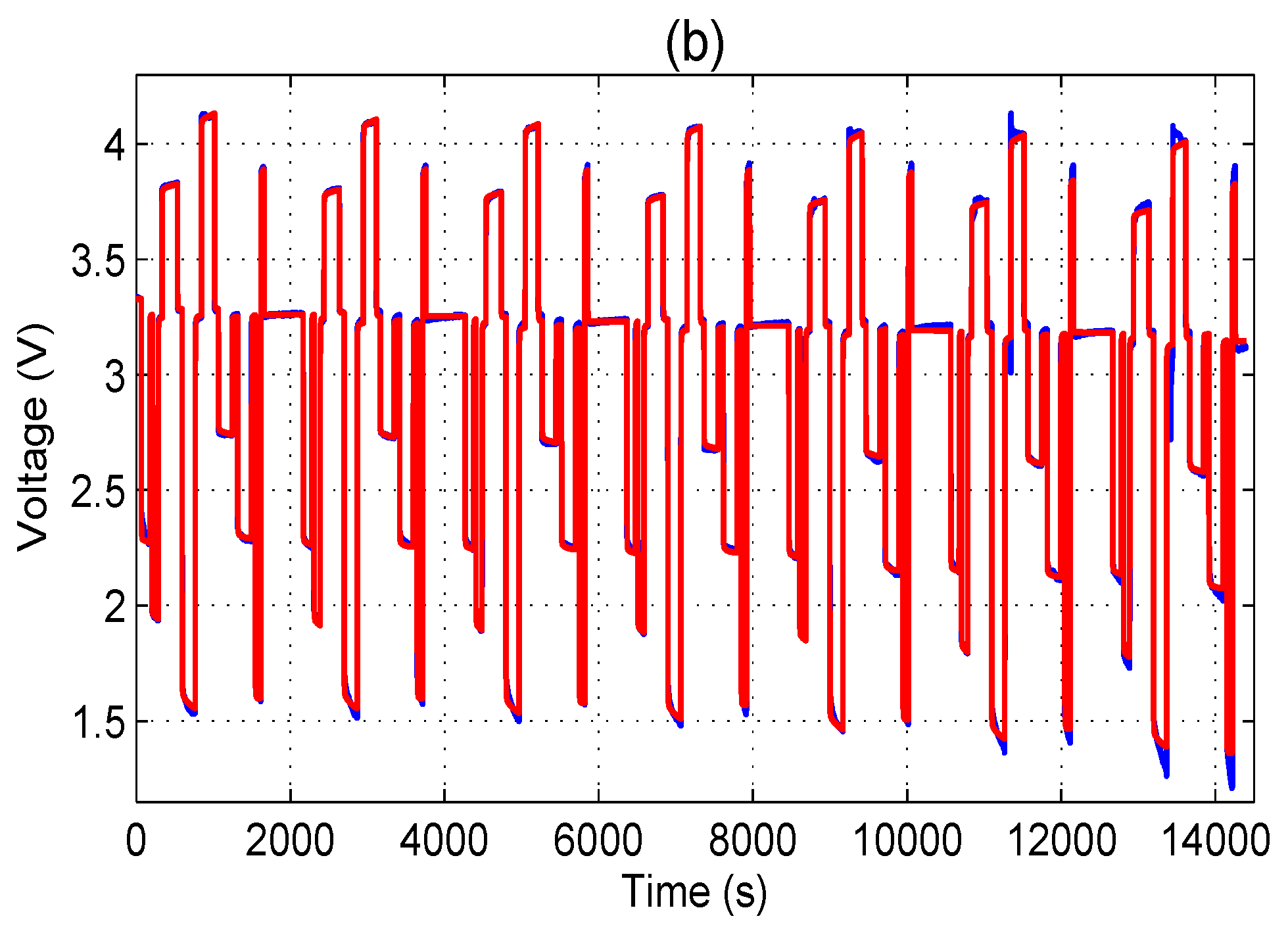
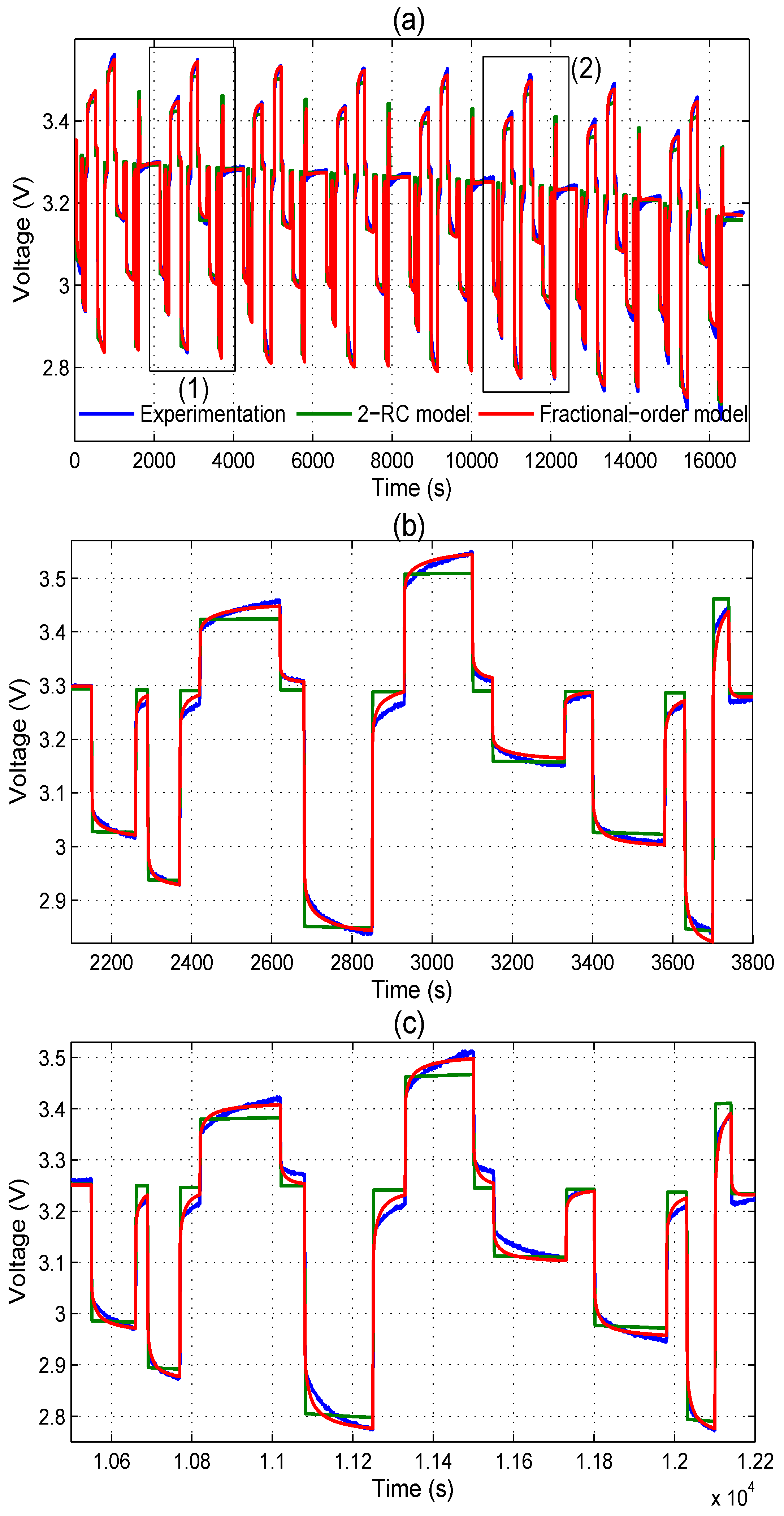
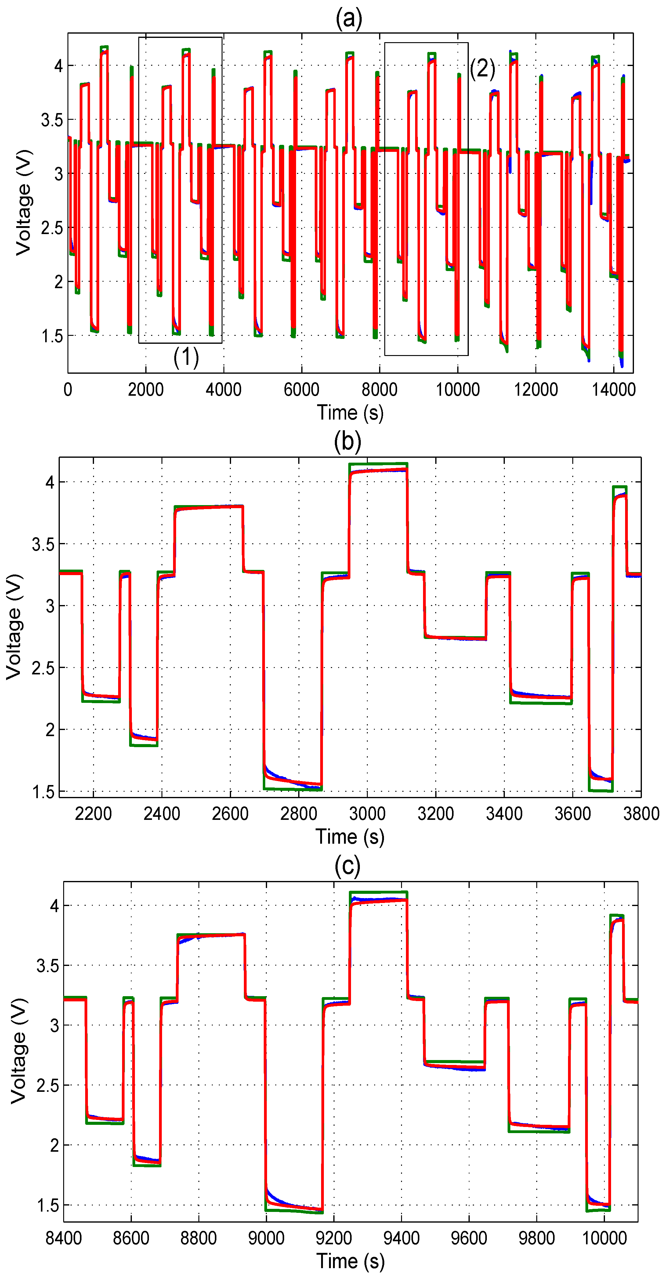
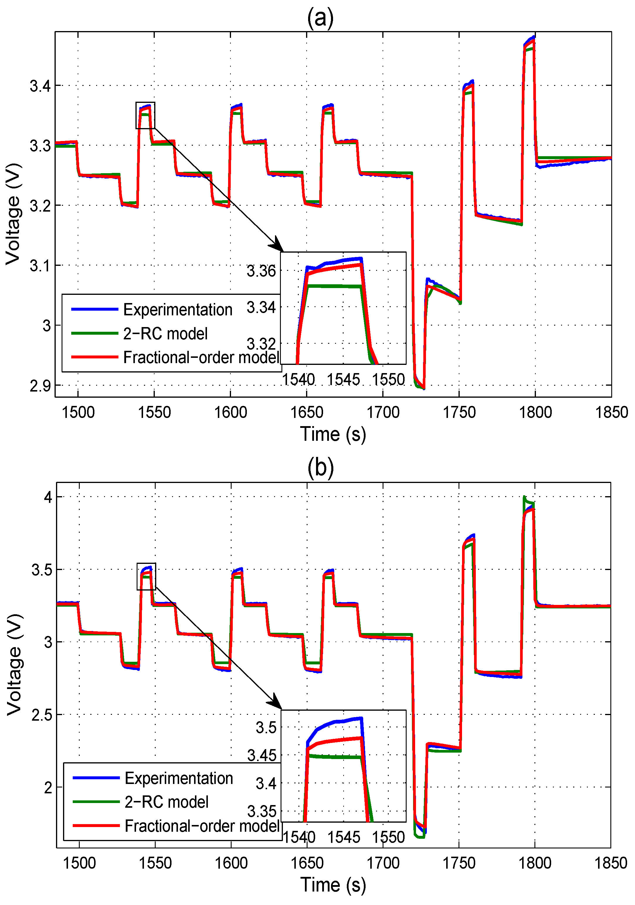
3.3. Accuracy of the Proposed Fractional-Order Model

To verify the accuracy of proposed model and evaluate its performance compared to other conventional modeling approaches, a classical equivalent circuit second-order RC (2-RC) model [30,31,32,33] is adopted here to use as the reference.
As shown in the Figure 7, the battery terminal voltage V can be estimated based on the model applied current I and battery state of charge (SOC), which can be calculated using the Coulomb counting method. The open circuit voltage V O C is a function of SOC. The series resistance R s and two parallel RC circuit including R t , s , R t , l , C t , l , and C t , l describe how the battery terminal voltage V dynamically changes under a variable applied current I .
The measured voltages of hybrid pulse test, 2-RC model output voltages and fractional-order model output voltages are shown and compared in Figure 8a and Figure 9a. The zoom-in at different SOC ranges of three curves are given in Figure 8b,c and Figure 9b,c for clearer illustration.
From the zoom-in comparisons shown in Figure 8 and Figure 9, it can be concluded that the proposed fractional-order model results show a very good accuracy compared with the experimental measurements over the entire SOC range. More specifically, the voltage dynamics of charging and discharging are correctly and precisely reproduced by the fractional-order model, which cannot be accurately predicted by the classical 2-RC model.
To further show the performance and advantages of the proposed fractional-order model, the 2-RC model output voltages and fractional-order model output voltages are compared with measured voltages for the one single cycle in DST, as shown in Figure 10.
In addition, the model prediction error numerical results during the entire test including root-mean-square error (RMSE) and maximum estimation error (MAE) are shown in Table 3. It can be seen that the proposed fractional-order model can achieve better accuracy compared to the 2-RC model.

4. Model Parameters Sensitivity Analysis

The fractional-order battery model can achieve a better dynamic modelling accuracy compared to the integer-order model, as shown and discussed in the previous section. However, it should be noted that each fractional-order parameter has its own influence with a different degree of sensitivity on the model output accuracy. Thus a parameter sensitivity study for a fractional-order model represents an important step for the model development, because such a study can indicate the most and least influencing parameter and leads to a better understanding of the model output dynamic, which is mainly affected by fractional-order parameters. In this section, a modelling parameter sensitivity analysis is presented and discussed in detail, based on the previously developed fractional-order lithium-ion battery model.

4.1. Sensitivity Analysis Method

To analyze the influence of different modelling parameters on the fractional-order model output voltage, the parameters sensitivity study is performed and discussed using statistical Multi-Parametric Sensitivity Analyze (MPSA) method [34,35]. The different steps of the MPSA method can be expressed as follows:
  • Select the fractional-order model parameters need to be analyzed, set an appropriate variation range (numerical boundary) of each parameter.
  • Generate a series of 700 independent random numbers with a uniform distribution within in the selected parameter design range.
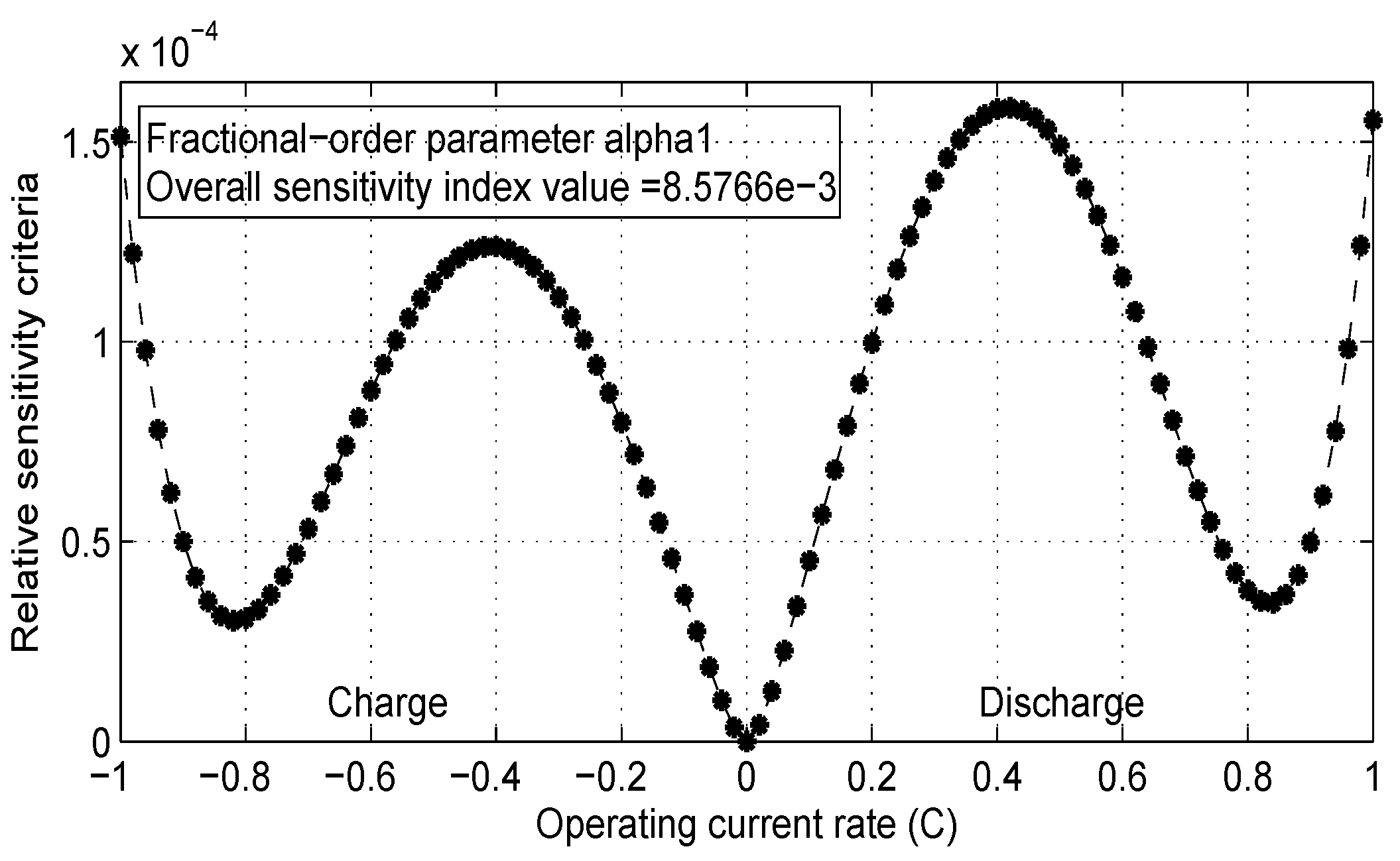
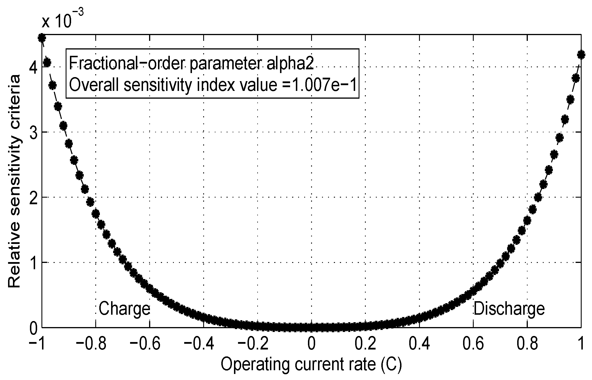
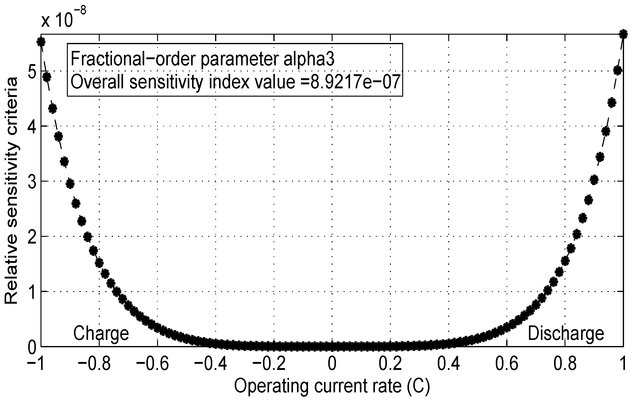
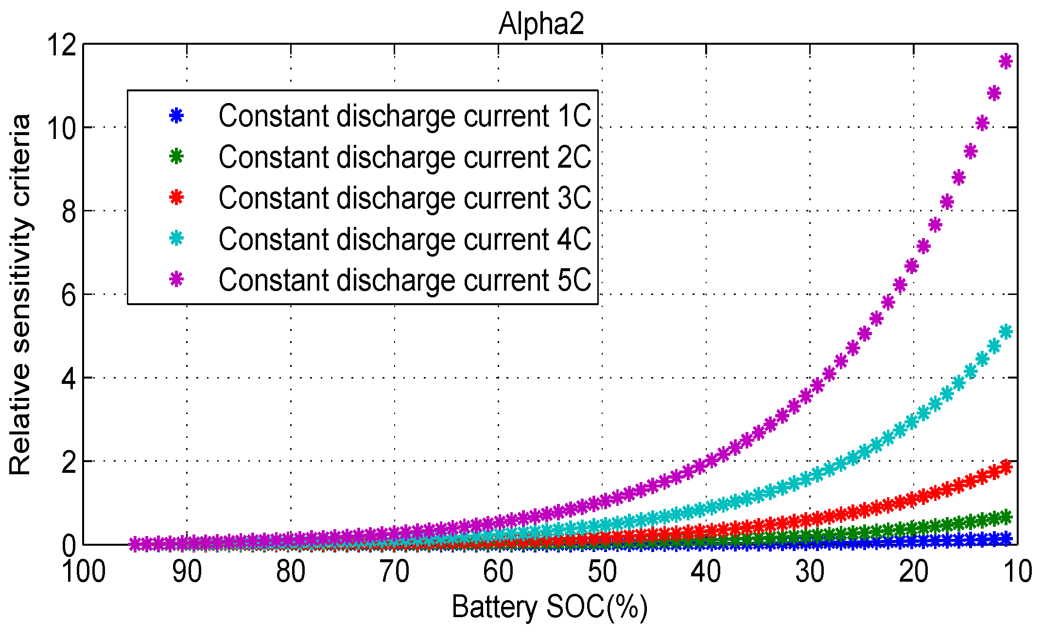
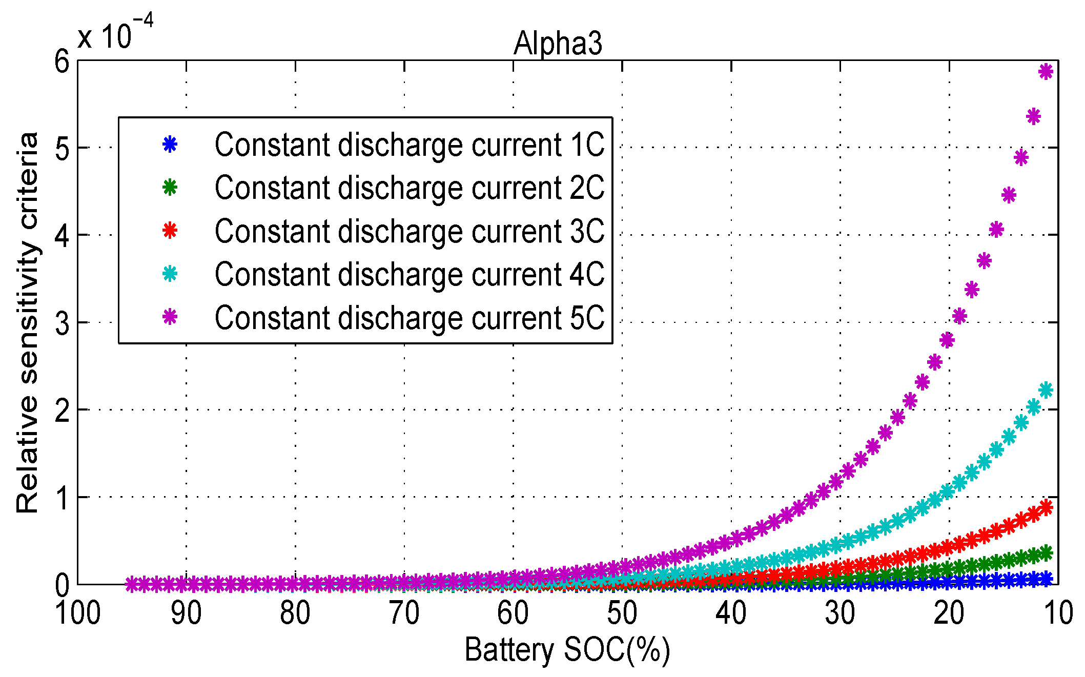
  • Run the fractional-order model using selected typical parameter values in order to get the model typical output voltage V t y p i c a l , i , where i is the operating current (positive for discharging, negative for charging); Run the fractional-order model using generated sets of 700 independent numbers for one parameter to get the model distribution output voltages V d i s t r i b u t i o n , i , n , where n is the generated numbers. Then the relative sensitivity criteria at different operating current values i of the selected parameter can be computed using the following equation:
    C i = n = 1 N = 700 ( V t y p i c a l , i V d i s t r i b u t i o n , i , n ) 2 / V d i s t r i b u t i o n , i , n
  • In order to calculate the overall parameter sensitivity over the whole battery operating current range, the parameter sensitivity index value S i can be defined as the sum of the relative sensitivity criteria at different battery operating current values:
    S i = i c h a r g e , m a x i d i s c h a r g e , m a x C i  

4.2. MPSA Method Results and Discussion

In the proposed fractional-order model, eight individual parameters have been selected for the sensitivity analysis. These parameters are: circuit component coefficients ( R s e i , R c t , C s e i , C d l , W d ) and fractional-order parameters ( α 1 , α 2 , α 3 ) . The typical values of these parameters have been chosen based on the GA-identified results, and variation range is set to ± 20 % of their typical value. By applying the previously described MPSA method, the sensitivity analysis results of fractional-order output voltage for each parameter over the experimental battery operating current rate range (from −1C to 1C) are summarized in Table 4.
It can be clearly seen from the Table 4 that, different parameters have different influence to the fractional-order model characteristics. Generally, they can be divided into three categories: highly sensitive parameters R s e i , α 2 (the index value is greater than 1.0 × 10 1 ), sensitive parameters C d l , α 1 , C s e i (the index value ranges from 1.0 × 10 4 to 1.0 × 10 1 ) and insensitive parameters R c t , α 3 , W d (the index value is less than 1.0 × 10 4 ).
The results indicate that, in the process of GA identification, the fractional-order model error between the output voltage and the experimentation could be effectively corrected by changing the values of highly sensitive and sensitive parameters. Thus, in order to improve the accuracy of fractional-order model and the efficiency of the identification process, the circuit element parameters ( R s e i , C s e i , C d l ) and fractional-order parameters ( α 1 , α 2 ) should be carefully chosen.
It should also be noted that, each parameters correspond different electrochemical dynamic behaviors as mentioned in Section 2.2. The parameter sensitivity analysis results further show that the lithium-ion migration through the SEI film layer (associated parameter R s e i ), and the double layer effects at the interface of electrolytes (associated parameters C d l , α 2 ) have an high impact on the battery terminal voltage. The capacitance of the SEI layer (associated parameters C s e i , α 1 ) have an medium impact on the battery terminal voltage. The activation kinetics in both negative and positive electrodes (associated parameter R c t ), and the lithium-ion diffusion processes in the active material of the electrodes (associated parameters W d , α 3 ) have an low impact on the battery terminal voltage. This meaningful information reveals that the battery internal dynamics have different degree influences on battery performance.
In addition to the analysis of index value for each parameter, the individual relative sensitivity criteria values of three fractional-order parameters at different operating current values are also presented. The relative sensitivity index value of fractional-order factors are presented in Figure 11. It can be seen from the Figure 11 that, fractional-order factor α 1 influences the battery output voltage over the entire current rate range, especially around ± 0.4 C point and at high current rate ( ± 1 C ).
The sensitivity criteria analysis results of fractional-order factors α 2 and α 3 are given in Figure 12 and Figure 13, respectively. It can be seen from the two figures that, the highly sensitive factor α 2 is the most sensitive parameter among the three fractional-order parameters. Furthermore, its value has a higher impact on the model output voltage at high current rate range. α 3 is an insensitive parameter to the fractional-order model, an increase of the current rate increases the relative sensitivity of the parameter α 3 also.
In order to give a comprehensive analysis of index value for each fractional-order parameter over the entire state of charge (SOC) range, the individual relative sensitivity criteria values of three fractional-order parameters at constant 1C to 5C discharge current are presented in Figure 14, Figure 15 and Figure 16.
It can be seen again from the three figures that the highly sensitive factor α 2 is the most sensitive parameter among the three fractional-order parameters. All the three fractional-order parameters relative sensitivity increase with the current rates. α 1 has the lowest impact on the model output voltage at 75% SOC. A decrease of the SOC increases the relative sensitivity of the parameters α 2 and α 3 .
The above sensitivity analysis results of these parameters can thus provide useful information during the parameter fitting process of the model.

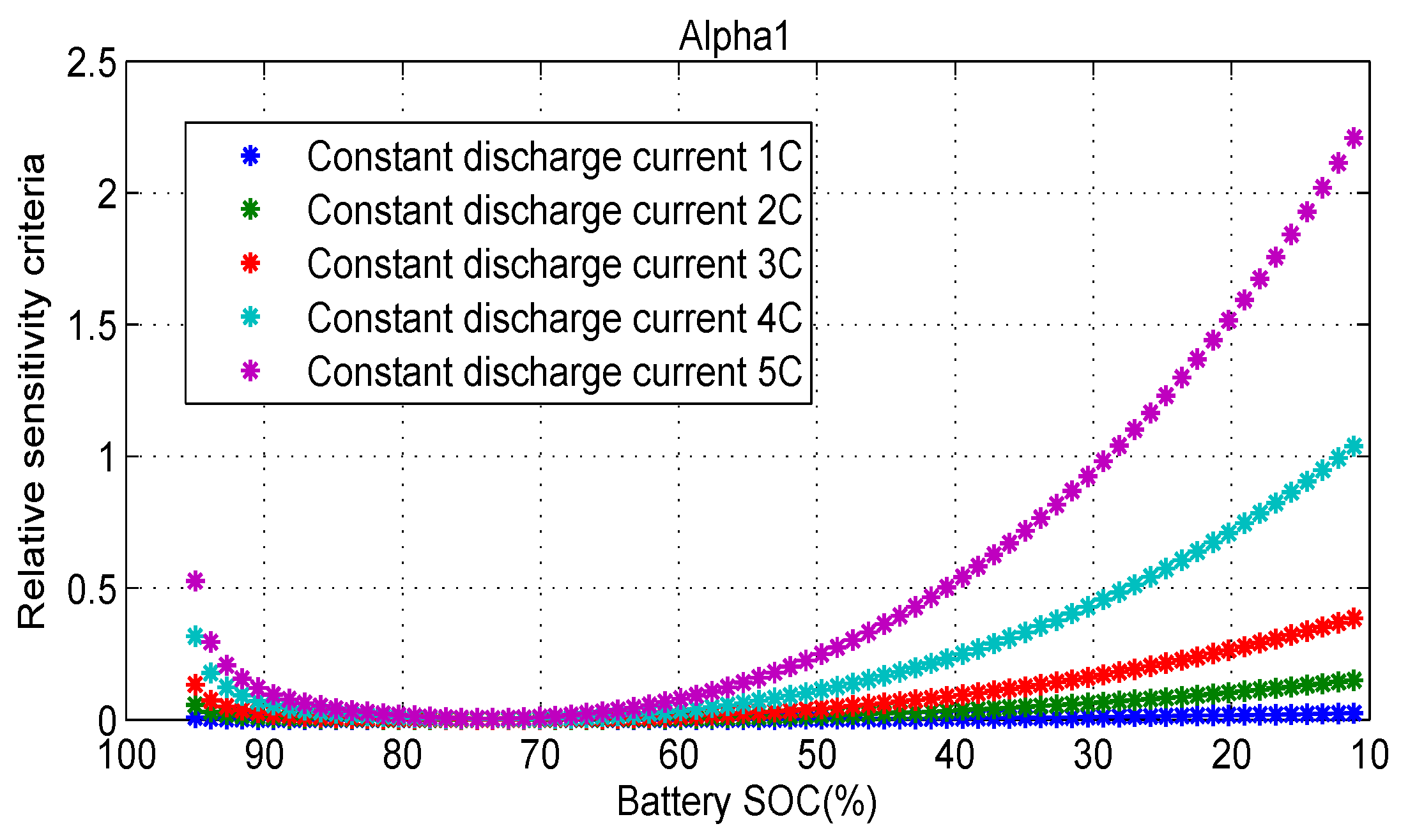
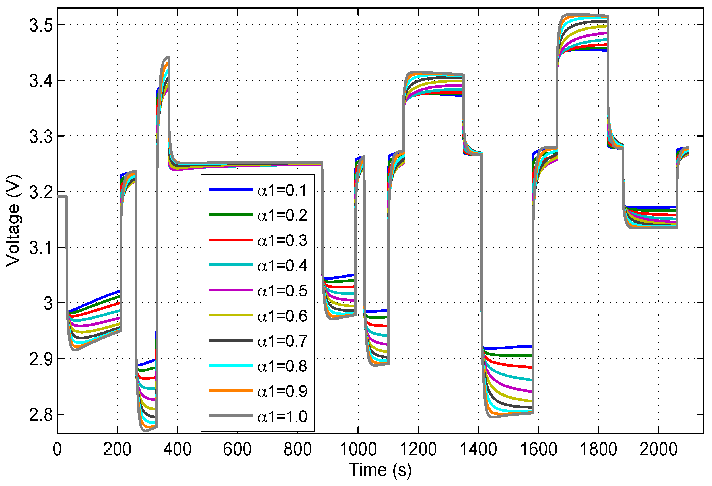
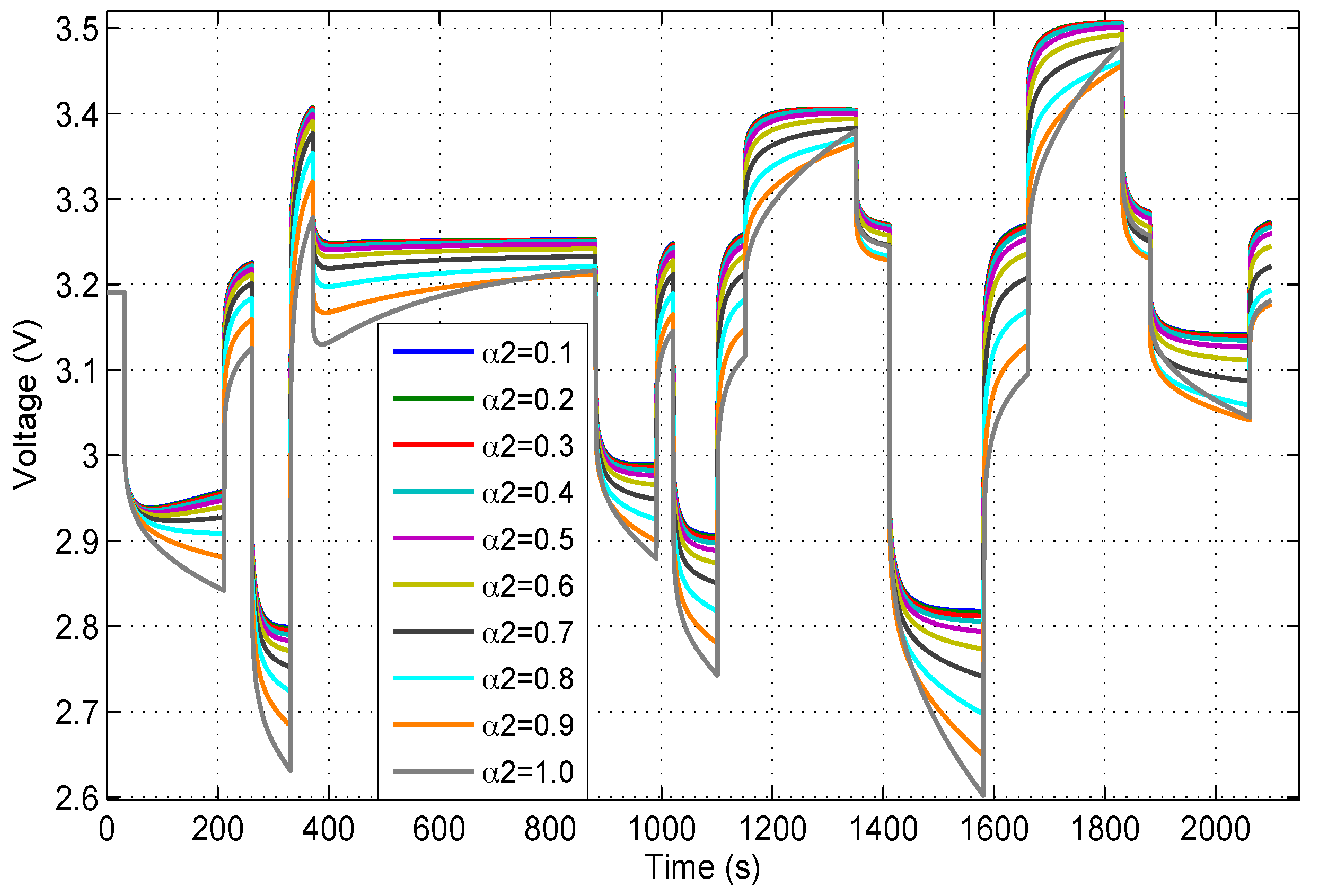
4.3. Dynamic Effect of Fractional-Order Parameters

According to the analysis results in the previous section, the proposed model output voltage is more sensitive to fractional-order parameters at medium and high current rate. For this reason, one single cycle in the hybrid pulse test (from Figure 4a), which includes various discharging /charging current rate pulses, is selected as the input for the proposed model to further investigate the influence of fractional-order parameters ( α 1 , α 2 , α 3 ) , on the model output dynamic behavior, as shown in Figure 17.
In this study, each fractional-order parameter changes its value from fractional values (0.1–0.9) to integer value of 1. The corresponding fractional-order model output voltages are then presented in Figure 18, Figure 19 and Figure 20.
From Figure 18, it is easy to observe that the sensitive fractional-order parameter α 1 have an important influence on the dynamic behavior of model output. Compared with classic integer-order models, the fractional-order model can effectively better describe the battery dynamic voltage responses with additional modeling degree of freedom.
The dynamic effect of the fractional-order for highly sensitive fractional-order parameter α 2 is shown in Figure 19. The variation of α 2 has indeed a stronger influence than α 1 , especially at high current. These results are in agreement with the previous analysis presented in Section 4.2. In addition, it can be clearly seen from the Figure 19 that, as the parameter α 2 increase from 0.1 to 1, the voltage dynamic transient time [36] gradually increases.
Figure 20 shows the different results of fractional-order model output voltage by changing value of parameter α 3 . In order to give a clearer show, the zoom-in at about 371 s and 1581 s for these ten curves are given. It can be seen clearly from figure that, the insensitive parameter α 3 has very small impact on the model output voltage. This results are also in agreement with the previous analysis presented in Section 4.2.
Summarizing the above analysis, it can be concluded that, the fractional-order parameters are more objective and original to reveal the nature of the dynamic physical phenomena.

5. Conclusions

In this paper, a novel fractional-order of lithium-ion battery has been developed in the first part. The fractional-order modeling approach, as well as the mathematical modeling equations, are introduced and explained based on an improved Oustaloup fractional-order approximation method. In this case, all the internal lithium-ion battery dynamic behaviors can be accurately captured by the proposed free fractional-orders elements. Compared to the classic integer-order equivalent circuit models in the literature, a fractional-order model has the advantage of higher modeling accuracy especially for the battery dynamic voltage behavior under transient operation conditions. The parameter identification of the proposed model is conducted using genetic algorithm, and the model has been validated experimentally with two different types of lithium-ion batteries. In order to evaluate its performance, one classical equivalent circuit second-order RC model is used for comparison purpose. The results show that the proposed model can achieve better accuracy over the entire battery SOC range, and the dynamic of charging/discharging voltages can be accurately reproduced by the fractional-order model.
Although parameter determination and identification are very important in the lithium-ion battery model development, especially for the fractional-order modelling which includes additional fractional-order parameters, very little information has been published so far in the literature on the analysis of sensitivity and dynamic effect of fractional-order parameters. This paper investigates in particular in the second part the sensitivities and dynamic effects of the parameters in the proposed fractional-order model. The parameter sensitivity analysis are performed using a statistical multi-parametric sensitivity analysis method. The effect of each parameter value deviation ( ± 20 % ) on the output voltages at different operating current values are presented and discussed. From the analysis results, the modelling parameters are divided into three categories based on their sensitivity index value: highly sensitive parameters ( R 1 and α 2 ), sensitive parameters ( C d l , 1 , C d l , 2 , α 1 ) and insensitive parameters ( R 2 , α 3 , W d ). These analysis results also reveal that the internal battery dynamics have different degrees of influence on battery performance. In addition, the influence of three fractional-order parameters value ( α 1 , α 2 , α 3 ) in proposed model on the output voltage are also shown and discussed. The analysis results can provide important modelling information for dynamic model development and parameter identification.

Appendix A

Fractional-order calculus is a mathematic expansion of classic integer-order calculus to fractional-order. As a more objective and original model to reveal the nature of the phenomenon, fractional-order model is particularly suitable for modeling dynamic physical systems including mass transport, diffusion and memory hysteresis. Its fundamental operator is expressed as t 0 D t α , where t 0 and t are the lower and upper bounds of integration, respectively. α is the order of derivative or integral ( α > 0 for derivative; α < 0 for integral).

A.1. Lacroix Definition

The first discussion of the fractional-order derivative appeared in a calculus was written by Lacroix definition, which expresses the nth derivative (for n m ) in terms of Euler gamma function Γ ( ) for the generalized factorial. The expression of well known Euler gamma function:
Γ ( μ ) = 0 t μ 1 e t d t
For the function y = x n , Lacroix definition expresses it as follows for all positive integers:
d m d x m x n = n ( n 1 ) ( n 2 ) ( n m + 1 ) x n m = n ! ( n m ) ! x n m = Γ ( n + 1 ) Γ ( n m + 1 ) x n m  
Let n be any positive integer, α > 0 , and x 0 , the Lacroix definition can be expressed by:
D α ( x n ) = Γ ( n + 1 ) Γ ( n α + 1 ) x n α  

A.2. Cauchy Definition

A popular definition used to describe fractional calculus is the Cauchy definition, which is recognized as one that preserves some important frequency properties, the Cauchy integral equation can be expressed as follows:
D α f ( x ) = Γ ( α + 1 ) 2 π j C f ( τ ) ( τ x ) α + 1 d α
where C is the smooth curve which surrounds single value and analytical domain of f ( x ) . From the definition of Cauchy integral equation definition, the fractional-order derivative of sine and cosine function can be expressed by:
d α d t α [ sin ( A t ) ] = A α sin ( A t + α π 2 )
d α d t α [ cos ( A t ) ] = A α cos ( A t + α π 2 )

A.3. Grünwald-Letnikov Definition

Another commonly used definition of fractional calculus is the Grünwald-Letnikov definition [37], which is expressed by:
t 0 D t α f ( t ) = l i m h 0 1 h α j = 0 [ t t 0 h ] ω j ( α ) f ( t j h )  
where h is the finite sampling interval. [ t t 0 h ] stands for the integer part of t t 0 h . ω j ( α ) represents the Newton binomial coefficient, can be expressed by:
ω j ( α ) = ( 1 ) j ( α j ) = ( 1 ) j α ! j ! ( α j ) ! = ( 1 ) j Γ ( α + 1 ) Γ ( j + 1 ) Γ ( α j + 1 )
The Grünwald-Letnikov definition is the most straightforward method for digital implementation of the fractional operator.

A.4. Riemann-Liouville Definition

In order to give the Riemann-Liouville definition, the fractional derivative of arbitrary order can be defined by using the Fourier transform of a function:
D α f ( x ) = 1 2 π ( i t ) α ( t ) e i x t d t
where stands for the Fourier transform of the function f . Based on Equation (A9), Liouville first definition states that any function f can be extended into a series n = 0 c n e a n x , where the real part of a n > 0 :
D α f ( x ) = n = 0 c n a n α e a n x
The Liouville second definition describes a fractional derivative of x n :
D α x n = ( 1 ) α Γ ( n + α ) Γ ( n ) x n α
for α > 0 and n > 0 .
The Riemann definition gives the integral form of the fractional derivative:
D β f ( x ) = 1 Γ ( β ) c x ( x t ) β 1 f ( t ) d t + Ψ ( x )
where Ψ ( x ) is a complementary function due to the ambiguity of the integration lower limit c .
Based on the above definitions, the fractional-order integral formula of Riemann-Liouville definition is expressed as follows:
t 0 D t β f ( t ) = d n d t n = 1 Γ ( β ) t 0 t ( t τ ) β 1 f ( τ ) d τ
and the fractional derivative equations of Riemann-Liouville definition is expressed as follow, for n 1 < α n :
t 0 D t α f ( t ) = d n d t n [ t 0 D t ( n α ) f ( t ) ] = 1 Γ ( n α ) d n d t n [ t 0 t f ( τ ) ( t τ ) α n + 1 d τ ]

A.5. Caputo Definition

The Caputo definition fractional-order derivative is expressed as follows:
0 D t α f ( t ) = 1 Γ ( m α ) 0 t f m ( τ ) ( t τ ) α m + 1 d τ
for m 1 < α < m .
It should be noted that, the difference between the Caputo and Riemann-Liouville definitions is mainly manifested in the constant derivative. The constant derivative of Caputo definition is bounded, another one is unbounded. The Caputo definition is more suitable to describe initial value problem of fractional-order differential equation.

A.6. Improved Oustaloup Recursive Approximation

This improved fractional calculus approach combines a boundary fitting optimization algorithm with traditional Oustaloup recursive approximation method [22,23], thus the calculation accuracy and efficiency are both satisfied. In this case, a satisfactory fitting result can be efficiently achieved in the whole pre-specified frequency range.

A.6.1. Traditional Oustaloup Recursive Approximation

The Oustaloup algorithm uses a set of integer-order filters for approximation of free fractional-order derivative in a certain frequency range [22]. For the approximation of fractional-order derivative s α in frequency range [ ω A , ω B ] , the term s / ω u can be substituted by frequency bounded differentiation transfer G f b d ( s ) :
G f b d ( s ) = C 0 1 + s / ω b 1 + s / ω h
where ω b ω h = ω u and C 0 = ω b / ω u = ω u / ω h , then the integer-order filter expression is given as:
G f ( s ) = ( ω u ω h ) α k = N N 1 + s / ω k * 1 + s / ω k
where the filter poles are defined by:
ω k * = ω b ( ω h ω b ) ( k + N ) + ( 1 α ) / 2 2 N + 1
and the filter zeros are defined by:
ω k = ω b ( ω h ω b ) ( k + N ) + ( 1 + α ) / 2 2 N + 1
It has been indicated that, in the Oustaloup algorithm, the numerical fitting accuracy is not satisfactory in the regions near the lower bound ω A and upper bound ω B .

A.6.2. Improved Oustaloup Recursive Approximation

To overcome the abovementioned drawback of boundary fitting in Oustaloup algorithm, an improved filter design is proposed in [23], which combines a boundary fitting optimization algorithm with traditional Oustaloup recursive approximation method, thus maintain simultaneously the calculation accuracy and efficiency. When the fitting frequency range specified at [ ω b , ω h ] , the fractional-order derivative s α can be approximated by:
K ( s ) = ( b s d ω b ) α ( 1 + d s 2 + d d s 2 + b ω h s ) α
where the b and d are constant coefficients. The first-order Taylor series approximation of Equation (A20) can be expressed by:
K ( s ) ( b s d ω b ) α [ 1 + α p ( s ) + α ( α 1 ) 2 p 2 ( s ) ]
where:
p ( s ) = d s 2 + d d s 2 + b ω h s
thus, the fractional-order derivative s α can be expressed by:
s α = ( d ω b b ) α ( d s 2 + b ω h s d ( 1 α ) s 2 + b ω h s + d α ) K ( s )
where the irrational fractional part of Equation (A23) can be approximated by a continuous-time rational model:
K ( s ) = lim N K N ( s ) = lim N k = N N ω k * + s ω k + s
where the poles of rank k are defined by:
ω k * = ( d ω b b ) α 2 k 2 N + 1
and the zeros of rank k are defined by:
ω k = ( b ω h d ) α + 2 k 2 N + 1

References

  1. Ravey, A.; Blunier, B.; Miraoui, A. Energy-Source-Sizing Methodology for Hybrid Fuel Cell Vehicles Based on Statistical Description of Driving Cycles. IEEE Trans. Veh. Technol. 2010, 61, 2452–2457. [Google Scholar] [CrossRef]
  2. Gao, F.; Blunier, B.; Miraoui, A.; El-Moudni, A. A multiphysic dynamic 1-d model of a proton-exchange-membrane fuel-cell stack for real-time simulation. IEEE Trans. Ind. Electron. 2010, 57, 1853–1864. [Google Scholar]
  3. Gao, F.; Blunier, B.; Miraoui, A. Proton Exchange Membrane Fuel Cell Modeling; Wiley: Hoboken, NJ, USA, 2012. [Google Scholar]
  4. Zhou, D.; Ravey, A.; Gao, F.; Paire, D.; Miraoui, A.; Zhang, K. On-line estimation of state-of-charge of Li-ion batteries using an Iterated Extended Kalman Particle Filter. In Proceedings of the IEEE Transportation Electrification Conference and Expo, Dearborn, MI, USA, 14–17 June 2015; pp. 1–5.
  5. Dai, H.; Wei, X.; Sun, Z.; Wang, J.; Gu, W. Online cell SOC estimation of Li-ion battery packs using a dual time-scale Kalman filtering for EV applications. Appl. Energy 2012, 95, 227–237. [Google Scholar]
  6. Ouyang, M.; Liu, G.; Lu, L.; Li, J.; Han, X. Enhancing the estimation accuracy in low state-of-charge area: A novel onboard battery model through surface state of charge determination. J. Power Sources 2014, 270, 221–237. [Google Scholar] [CrossRef]
  7. Plett, G.L. Extended Kalman filtering for battery management systems of LiPB-based HEV battery packs, Part2: Modeling and identification, Part3: State and parameter estimation. J. Power Sources 2004, 134, 252–292. [Google Scholar] [CrossRef]
  8. Hua, X.; Li, S.; Peng, H. A comparative study of equivalent circuit models for Li-ion batteries. J. Power Sources 2012, 198, 359–367. [Google Scholar] [CrossRef]
  9. Doyle, M.; Newman, J.; Gozdz, A.; Schmutz, C.; Tarascon, J. Comparison of Modeling Predictions with Experimental Data from Plastic Lithium-ion Cells. J. Electrochem. Soc. 1996, 143, 1890–1903. [Google Scholar] [CrossRef]
  10. Lee, J.L.; Chemistruck, A.; Plett, G.L. One-dimensional physics-based reduced-order model of lithium-ion dynamics. J. Power Sources 2012, 220, 430–448. [Google Scholar] [CrossRef]
  11. Guo, M.; Sikha, G.; White, R.E. Single-Particle Model for a Lithium-Ion Cell: Thermal Behavior. J. Electrochem. Soc. 2011, 158, 122–132. [Google Scholar] [CrossRef]
  12. Prada, E.; Domenico, D.D.; Creff, Y.; Bernard, J.; Sauvant-Moynot, V.; Huet, F. Simplified Electrochemical and Thermal Model of LiFePO4-Graphite Li-Ion Batteries for Fast Charge Applications. J. Electrochem. Soc. 2012, 159, 1508–1519. [Google Scholar] [CrossRef]
  13. Seaman, A.; Dao, T.; Mcphee, J. A survey of mathematics-based equivalent-circuit and electrochemical battery models for hybrid and electric vehicle simulation. J. Power Sources 2014, 256, 410–423. [Google Scholar] [CrossRef]
  14. Zhou, D.; Ravey, A.; Gao, F.; Miraoui, A.; Zhang, K. On-Line Estimation of Lithium Polymer Batteries State-of-Charge Using Particle Filter Based Data Fusion with Multi-Models Approach. In Proceedings of the IEEE Industry Applications Society Annual Meeting, Addison, TX, USA, 18–22 October 2015; pp. 1–8.
  15. Zhou, D.; Zhang, K.; Ravey, A.; Gao, F.; Miraoui, A. On-Line Estimation of Lithium Polymer Batteries State-of-Charge Using Particle Filter Based Data Fusion with Multi-Models Approach. IEEE Trans. Ind. Appl. 2015. [Google Scholar] [CrossRef]
  16. Debnath, L. Recent applications of fractional calculus to science and engineering. Int. J. Math. Math. Sci. 2003, 54, 3413–3442. [Google Scholar] [CrossRef]
  17. Zhong, F.; Li, H.; Zhong, S.; Zhong, Q.; Yin, C. An SOC estimation approach based on adaptive sliding mode observer and fractional order equivalent circuit model for lithium-ion batteries. Commun. Nonlinear Sci. Numer Simulat. 2015, 24, 127–144. [Google Scholar] [CrossRef]
  18. Cugnet, M.; Sabatier, J.; Laruelle, S.; Grugeon, S.; Sahut, B.; Oustaloup, A.; Tarascon, J. On Lead-Acid-Battery Resistance and Cranking-Capability Estimation. IEEE Trans. Ind. Electron. 2010, 57, 909–917. [Google Scholar] [CrossRef]
  19. Alavi, S.M.M.; Birkl, C.R.; Howey, D.A. Time-domain fitting of battery electrochemical impedance models. J. Power Sources 2015, 288, 345–352. [Google Scholar] [CrossRef]
  20. Wu, H.; Yuan, S.; Yin, C. A Lithium-Ion Battery Fractional Order State Space Model and its Time Domain System Identification. In Proceedings of the FISITA World Automotive Congress, Beijing, China, 27–30 November 2012; pp. 795–805.
  21. Sabatier, J.; Cugnet, M.; Laruelle, S.; Grugeon, S.; Sahut, B.; Oustaloup, A.; Tarascon, J. A fractional order model for lead-acid battery crankability estimation. Commun. Nonlinear Sci. Numer Simulat. 2010, 15, 1308–1317. [Google Scholar] [CrossRef]
  22. Oustaloup, A.; Levron, F.; Mathieu, B.; Nanot, F.M. Frequency-Band Complex Noninteger Differentiator: Characterization and Synthesis. IEEE Trans. Circuit Syst. 2000, 47, 25–39. [Google Scholar] [CrossRef]
  23. Xue, D.; Zhao, C.; Chen, Y. A Modified Approximation Method of Fractional Order System. In Proceedings of the International Conference on Mechatronics and Automation, Luoyang, China, 25–28 June 2006; pp. 1043–1048.
  24. Andre, D.; Meiler, M.; Steiner, K.; Wimmer, C.; Soczka-Guth, T.; Sauer, D.U. Characterization of high-power lithium-ion batteries by electrochemical impedance spectroscopy. I. Experimental investigation. J. Power Sources 2011, 196, 5334–5341. [Google Scholar] [CrossRef]
  25. Zhang, S.; Xu, K.; Jow, T. EIS study on the formation of solid electrolyte interface in Li-ion battery. Electrochim. Acta 2006, 51, 1636–1640. [Google Scholar] [CrossRef]
  26. Radvanyi, E.; Havenbergh, K.; Porcher, W.; Jouanneau, S.; Bridel, J.; Put, S.; Franger, S. Study and modeling of the Solid Electrolyte Interphase behavior on nano-silicon anodes by Electrochemical Impedance Spectroscopy. Electrochim. Acta 2014, 137, 751–757. [Google Scholar] [CrossRef]
  27. Forman, J.; Moura, S.; Stein, J.; Fathy, H. Genetic identification and fisher identifiability analysis of the Doyle–Fuller–Newman model from experimental cycling of a LiFePO4 cell. J. Power Sources 2012, 210, 263–275. [Google Scholar] [CrossRef]
  28. Singh, A.; Izadian, A.; Anwar, S. Model based condition monitoring in lithium-ion batteries. J. Power Sources 2014, 268, 459–468. [Google Scholar] [CrossRef]
  29. He, H.; Xiong, R.; Fan, J. Evaluation of Lithium-Ion Battery Equivalent Circuit Models for State of Charge Estimation by an Experimental Approach. Energies 2011, 4, 582–598. [Google Scholar] [CrossRef]
  30. Chen, M.; Rincon-Mora, G. Accurate electrical battery model capable of predicting runtime and IV performance. IEEE Trans. Energy Convers. 2006, 21, 504–511. [Google Scholar] [CrossRef]
  31. Fares, R.L.; Webber, M.E. Combining a dynamic battery model with high-resolution smart grid data to assess microgrid islanding lifetime. Appl. Energy 2015, 137, 482–489. [Google Scholar] [CrossRef]
  32. Fares, R.L.; Webber, M.E. A flexible model for economic operational management of grid battery energy storage. Energy 2014, 78, 768–776. [Google Scholar] [CrossRef]
  33. Fridholm, B.; Wik, T.; Nilsson, M. Robust recursive impedance estimation for automotive lithium-ion batteries. J. Power Sources 2016, 304, 33–41. [Google Scholar] [CrossRef]
  34. Choi, J.; Harvey, J.; Conklin, M. Use of Multi-Parameter Sensitivity Analysis to Determine Relative Importance of Factors Influencing Natural Attenuation of Mining Contaminants. In US geological survey toxic substances hydrology program; Proceedings of the Technical Meeting, Charleston, SC, USA, 8–12 March 1999; pp. 185–192.
  35. Zhao, D.; Gao, F.; Massonnat, P.; Dou, M.; Miraoui, A. Parameter Sensitivity Analysis and Local Temperature Distribution Effect for a PEMFC System. IEEE Trans. Energy Convers. 2015, 30, 1008–1018. [Google Scholar] [CrossRef]
  36. Gao, F.; Blunier, B.; Miraoui, A.; El-Moudni, A. Proton exchange membrane fuel cell multi-physical dynamics and stack spatial non-homogeneity analyses. J. Power Sources 2010, 195, 7609–7626. [Google Scholar] [CrossRef]
  37. Petras, I. Fractional-Order Nonlinear Systems: Modeling. Analysis and Simulation; Springer: Berlin, Germany, 2011. [Google Scholar]
Figure 1. Schematic diagram of the lithium-ion battery internal dynamic phenomena, the corresponding EIS Nyquist curve and equivalent fractional-order impedance circuit.
Energies 09 00123 g001
Figure 2. GA-based parameters identification framework design for fractional-order model.
Energies 09 00123 g002
Figure 3. Battery test bench architecture.
Energies 09 00123 g003
Figure 4. (a) Dataset of hybrid pulse test on WB-LYP40AHA: current; (b) Dataset of hybrid pulse test on WB-LYP40AHA: voltage and SOC.
Energies 09 00123 g004
Figure 5. (a) Dataset of dynamic stress test (DST) on WB-LYP40AHA: current; (b) Dataset of DST on WB-LYP40AHA: voltage and SOC.
Energies 09 00123 g005aEnergies 09 00123 g005b
Figure 6. (a) Experimental and identification results of hybrid pulse test: WB-LYP40AHA; (b) Experimental and identification results of hybrid pulse test: LiFePO4.
Energies 09 00123 g006aEnergies 09 00123 g006b
Figure 7. Classical equivalent circuit second-order RC model
Energies 09 00123 g007
Figure 8. (a) Comparison of actual voltages of hybrid pulse test, 2-RC model output voltages and fractional-order model output voltages for WB-LYP40AHA: all SOC range; (b) zoom-in at Section 1; (c) zoom-in at Section 2.
Energies 09 00123 g008
Figure 9. (a) Comparison of actual voltages of hybrid pulse test, 2-RC model output voltages and fractional-order model output voltages for LiFePO4: all SOC range; (b) zoom-in at Section 1; (c) zoom-in at Section 2.
Energies 09 00123 g009
Figure 10. (a) Comparison of actual voltages for the one single in cycle DST, 2-RC model output voltages and fractional-order model output voltages: WB-LYP40AHA; (b) Comparison of actual voltages for the one single in cycle DST, 2-RC model output voltages and fractional-order model output voltages: LiFePO4.
Energies 09 00123 g010
Figure 11. Sensitivity index values of sensitive parameter fractional-order factor α 1 at different operating current values.
Energies 09 00123 g011
Figure 12. Sensitivity index values of highly sensitive parameter fractional-order factor α 2 at different operating current values.
Energies 09 00123 g012
Figure 13. Sensitivity index values of insensitive parameter fractional-order factor α 3 at different operating current values.
Energies 09 00123 g013
Figure 14. Analysis of index values under different current rates discharge test: the sensitivity index values of sensitive parameter fractional-order factor α 1 .
Energies 09 00123 g014
Figure 15. Analysis of index values under different current rates discharge test: the sensitivity index values of highly sensitive parameter fractional-order factor α 2 .
Energies 09 00123 g015
Figure 16. Analysis of index values under different current rates discharge test: the sensitivity index values of insensitive parameter fractional-order factor α 3 .
Energies 09 00123 g016
Figure 17. Different discharging/charging current rate pulses of one single cycle in hybrid pulse test.
Energies 09 00123 g017
Figure 18. Differences of fractional-order model output voltage by changing value of α 1 .
Energies 09 00123 g018
Figure 19. Differences of fractional-order model output voltage by changing value of α 2 .
Energies 09 00123 g019
Figure 20. Differences of fractional-order model output voltage by changing value of α 3 .
Energies 09 00123 g020
Table 1. Specifications of the batteries.
BatteryNominal capacity (Ah)Nominal voltage (V)Max voltage (V)Operating temperature (℃)
WB-LYP40AHA40.03.44.0−45~85
LiFePO415.03.24.3−45~70
Table 2. Parameter identification results.
ParameterWB-LYP40AHALiFePO4
R o 7.40 × 10 3 6.69 × 10 2
R s e i 4.30 × 10 3 4.32 × 10 2
R c t 5.43 × 10 2 2.7829 × 10 0
C s e i 5.19 × 10 2 2.25548 × 10 1
C d l 4.77 × 10 3 2.65 × 10 3
W d 9.91 × 10 3 9.06 × 10 3
α 1 3.656 × 10 1 8.539 × 10 1
α 2 3.155 × 10 1 6.074 × 10 1
α 3 8.927 × 10 1 5.527 × 10 1
Table 3. RMSEs and MAEs for WB-LYP40AHA and LiFePO4 battery.
BatteryTest2-RC ModelFractional-Order Model
RMSE (%)MAE (V)RMSE (%)MAE (V)
WB-LYP40AHAHybrid pulse test2.25820.18601.31000.1307
DST0.74300.03070.36400.0125
LiFePO4Hybrid pulse test5.05040.79913.56210.4052
DST5.03100.44381.22030.0386
Table 4. Fractional-order model parameters sensitivity results.
ParameterTypical valueVariation rangeIndex valueSensitivity
R s e i 4.30 × 10 3 ± 20 % 1.0594 × 10 0 Highly sensitive
α 2 3.155 × 10 1 ± 20 % 1.0007 × 10 1 Highly sensitive
C d l 4.77 × 10 3 ± 20 % 1.2227 × 10 2 Sensitive
α 1 3.656 × 10 1 ± 20 % 8.5766 × 10 3 Sensitive
C s e i 5.19 × 10 2 ± 20 % 8.5792 × 10 4 Sensitive
R c t 5.43 × 10 2 ± 20 % 1.3383 × 10 5 Insensitive
α 3 8.927 × 10 1 ± 20 % 8.9217 × 10 7 Insensitive
W d 9.91 × 10 3 ± 20 % 1.4851 × 10 7 Insensitive

