1. Introduction
Advances in wireless power transmission (WPT) technology have remarkably facilitated the rapid development of mobile electronic devices, biomedical devices, industrial, automotive and space satellite applications. In general WPT techniques are classified into three types [
1] based on the transmission techniques: (1) the electromagnetic (EM) radiation technique, which transmits microwave energy over long distances and is used for space satellite applications [
1]; (2) the inductive coupling technique, which allows the transfer of energy over very short distances and is used in wireless charging applications, such as laptops, mobile phones and biomedical implants [
1,
2,
3,
4,
5]. For energy harvesting applications, the work presented in [
6] depicted long-range energy transfer based on inductive coupling for a distance of 6 m, but the power received was confined to 10.9 mW for a 246-W DC power input. Further, in [
7], a designed and fabricated inductive power transfer system displayed higher efficiency of 77% at a distance of 30 cm. The work showed effective improvement in achieving power transfer efficiency for a longer range, but beyond 30 cm, the efficiency decreased gradually. Therefore, for short-range power transfer, the inductive coupling method is usually employed. However, as the distance range increases, the inductive coupling method becomes unsuitable as the power transfer efficiency rapidly decreases. (3) To increase the power transmission range, magnetically-coupled resonance power transfer is proposed in [
8,
9], which effectively increased the transfer range in comparison to the inductive coupling method. This technique is based on the concept that two resonators with a similar resonance frequency effectively exchange power, and it is widely used in consumer electronics and automotive applications [
10,
11,
12]. However, in practical systems, power transfer efficiency drops rapidly, when the distance between the coils increases or the coils are misaligned [
11,
13]. As all of the applications demand a highly efficient end-to-end wireless power delivery system, it is essentially important to consider techniques to achieve optimal efficiency.
To obtain maximum efficiency for a WPT system, several methods have been proposed and studied in prior works [
11,
12,
13,
14,
15,
16,
17,
18,
19,
20,
21]. These methods consist of adaptive circuits to optimize efficiency based on frequency control, impedance matching control, Q-factor tuning control and adjusting the coupling coefficient. The work in [
11] reports a frequency tuning technique to mitigate the effect of frequency splitting and to improve the efficiency of the WPT system. However, the technique violates the frequency standards (Industrial Scientific Medical (ISM) Band) of wireless power transmission as it requires a wide frequency bandwidth. In [
12,
14,
15,
16,
17,
22], adaptive impedance matching-based efficiency improvement is proposed. However, the range of tuning to obtain optimal efficiency was limited by the varactors employed in the circuit, and additionally, varactor losses reduced the total efficiency of the system. The work in [
13,
18,
19,
20,
21] details optimizing the efficiency based on varying the coupling between the coils. However, [
13,
18,
19,
20] describes the method based on manually changing the distance between the coils to vary the coupling coefficient and obtain the optimal efficiency, whereas [
21] suggests manually misaligning the source coil to vary the coupling coefficient to obtain maximum power transfer efficiency. However, in practical cases, the manual adjustment of the coils is not a viable option to obtain maximum power transfer efficiency.
In this paper, we propose a WPT system based on a controlled switching technique with multiple loop coils to optimize the power transfer efficiency over a wide operational range. This method involves several loop coils with different sizes at the transmitter side and receiver side. The loop coils are adequately selected to adjust the coupling coefficient, so as to obtain the optimum coupling coefficient for achieving maximum power transfer efficiency with varying distance between the transmitter side and receiver side over a wide distance range. The detailed analysis of the system is provided in the following sections. The paper is organized as follows:
Section 2 details the analysis of the four-coil WPT system based on a circuit model.
Section 3 analyzes the optimization strategy for maximum power transmission efficiency, and the proposed efficiency optimization method is described in
Section 4. The simulation and experimental results are discussed in
Section 5, followed by the conclusion in
Section 6.
3. Optimization of Power Transfer Efficiency
The designed WPT system has to be optimized to achieve maximum power transfer efficiency for a particular range with fixed resonating frequency (13.56-MHz ISM band frequency for our experimental purposes). The Equation (
13) implies that the power transfer efficiency is influenced by the coupling factors
,
and
for a given
,
,
and
. Further, the coupling coefficient is a strong function of the distance between the coils. For symmetric coils, Tx and Rx, with
n turns and radius
r (
r <<
), the mutual inductance is calculated based on the Neumann formula and is given by:
where
is the permeability of free space. Hence, for symmetric coils from Equations (1) and (15),
is evaluated as:
where
is the self-inductance of each coil. Equation (
1) implies that
is directly proportional to
, which indicates the dramatic decrease in the efficiency with distance between the coils.
The efficiency can be maximized for a given distance
and particular resonance frequency, by choosing the optimum value of coupling coefficients
and
, as efficiency is a dependent parameter of the coupling coefficients, stated in Equation (
13). Two case studies are taken into consideration for the evaluation of the efficiency for a particular distance (
) between the Tx and Rx with fixed resonant frequency (13.56 MHz). The Tx and Rx coils are assumed to be identical for the analysis. Hence the quality factors of Tx and Rx are equal (
=
).
Case 1: ≠
The efficiency can be maximized for given
(or
) and
by optimizing
, such that:
From Equation (
17), the optimal value of
is computed as given in Equation (
18).
Equation (
18) is substituted in Equation (
13) to obtain optimum
for a given distance.
Case 2: =
For a given
(or
) with symmetrical coils, the coupling coefficients
=
, and the quality factors
=
and
=
. Based on these conditions, Equation (
13) is further simplified, and the magnitude of
is given as:
To obtain the optimum
to maximize the efficiency for a given distance, the procedure in Equation (
17) is repeated, and the optimum value
is obtained from Equation (
21).
Equation (
21) is substituted in Equation (
20) to obtain optimum
for a given distance and is given by:
5. Simulation and Experimental Results
The proposed power transfer efficiency enhancement technique for the WPT system is validated based on simulation and experimental results. From Equations (13), (14) and (16), it is noted that the power transfer efficiency is a strong function of the distance between the Tx and Rx (
). However, for our design considerations that involve optimization of the power transfer efficiency for various
at a fixed frequency, Cases 1 and 2 in
Section 4 are considered. The proposed work aims at optimizing
for achieving high efficiency for a particular
(
). Since, Equation (
16) is an approximated Neumann formula for
r≪
, the original Neumann formula is employed to predict
for a particular
, as reported in [
26,
27,
28]. The mutual inductance between the Tx and Rx is computed initially for two single turn loops
x and
y as given in Equation (
23).
where
is the permittivity of free space and
r is the distance between the incremental lines
and
. For the computation of the mutual inductance of multiple turn coils, with
and
turns, the Equation in (
23) is decomposed into sets of
and
closed loops and approximated for
as in Equation (
24) [
26,
27,
28]. The coupling coefficient is further calculated based on the Equation in (1).
In Case 1, for varying
, the power supply at the source end is switched to one of the three loops, such that
in Equation (
18) is satisfied.
in Equation (
18) is calculated as a dependable parameter of
.
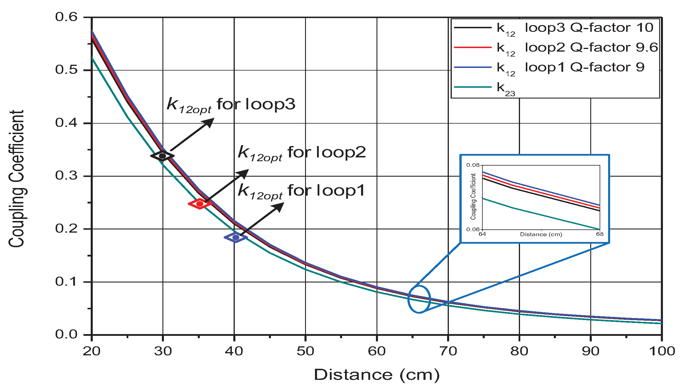
Figure 4 shows the computed results for a Case 1-type system. The computed
as a function of
based on Equations (1), (23) and (24) is represented in
Figure 4 using the measured value of coil parameters as given in the
Table 2. Furthermore, the optimal
for varying
, derived from Equation (
18) for three different loops at the source end (loop1, loop2, loop3) with loop4 as the load coil, is depicted in
Figure 4. The obtained
for each loop is indicated in
Figure 4. Loop1 in the system is targeted for
= 30 cm, loop2 for
= 35 cm and loop 4
= 40 cm.
Figure 4 validates that the proposed technique can be used to obtain optimal
(
) for varying
.
In Case 2, with respect to varying
, the power supply is switched to one of the three loops at the source end simultaneously with the identical loops at the receiver end, such that
in Equation (
21) is satisfied.
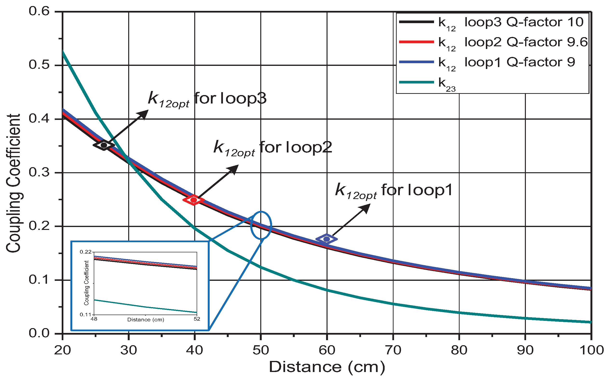
The computed
with reference to
is depicted in
Figure 5. The different loop coil parameters, as in
Table 2, are substituted in Equation (
20) and the obtained
with respect to
is plotted. Furthermore, the obtained
for each loop is illustrated in
Figure 5. Loop1 is intended for
= 25 cm, loop2 for
= 35 cm and loop 4
= 60 cm. Thus,
Figure 5 validates that the proposed Case 2 technique can be used to obtain
for a wider range of distances in comparison to Case 1.
The system is simulated with the Agilent ADS (Advanced Design System) tool for the theoretical verification. The circuit simulation is performed with the extracted parameters from the measurement
Table 2 and the computed
and
parameters.
Figure 6 and
Figure 7 illustrate the
magnitude of the system for Case 1 at a 13.56-MHz input frequency, with respect to coupling coefficient
and distance
. The
Figure 6 and
Figure 7 indicate that one of the three loops is chosen to achieve maximum
for a particular distance. From Equation (
14) and
Figure 7, for the maximum efficiency up to
= 31 cm, loop3 is connected to the supply; for
> 31 cm and
≤ 36 cm, loop2 is connected to the supply; and for
> 36 cm, loop1 is connected to the supply. This validates that the proposed loop switching technique aids obtaining the maximum efficiency for variable distances between the transmitter and receiver.
The simulated
of the system for Case 2 with respect to
and
is depicted in
Figure 8 and
Figure 9, respectively. From Equation (
14) and the graph in
Figure 9, maximum efficiency is derived for
≤ 33 cm when loop3 is connected to the supply; for maximum efficiency in the range
> 33 cm and
≤ 52 cm, loop2 is connected to the supply; and for
> 52 cm, loop1 is connected to the supply. The plot in
Figure 9 referring to Case 2 in comparison to
Figure 7 referring to Case 1 exhibits higher efficiency over a wider range of
, which validates the Case 2 system to be more effective for implementation. The resultant high efficiency can be correlated to the
plotted in
Figure 4 and
Figure 5. It is observed that the obtained
for the three loops closely follows
computed in
Figure 5 in comparison to the computed
in
Figure 4. The closer the computed
to the obtained
, the better the efficiency obtained.
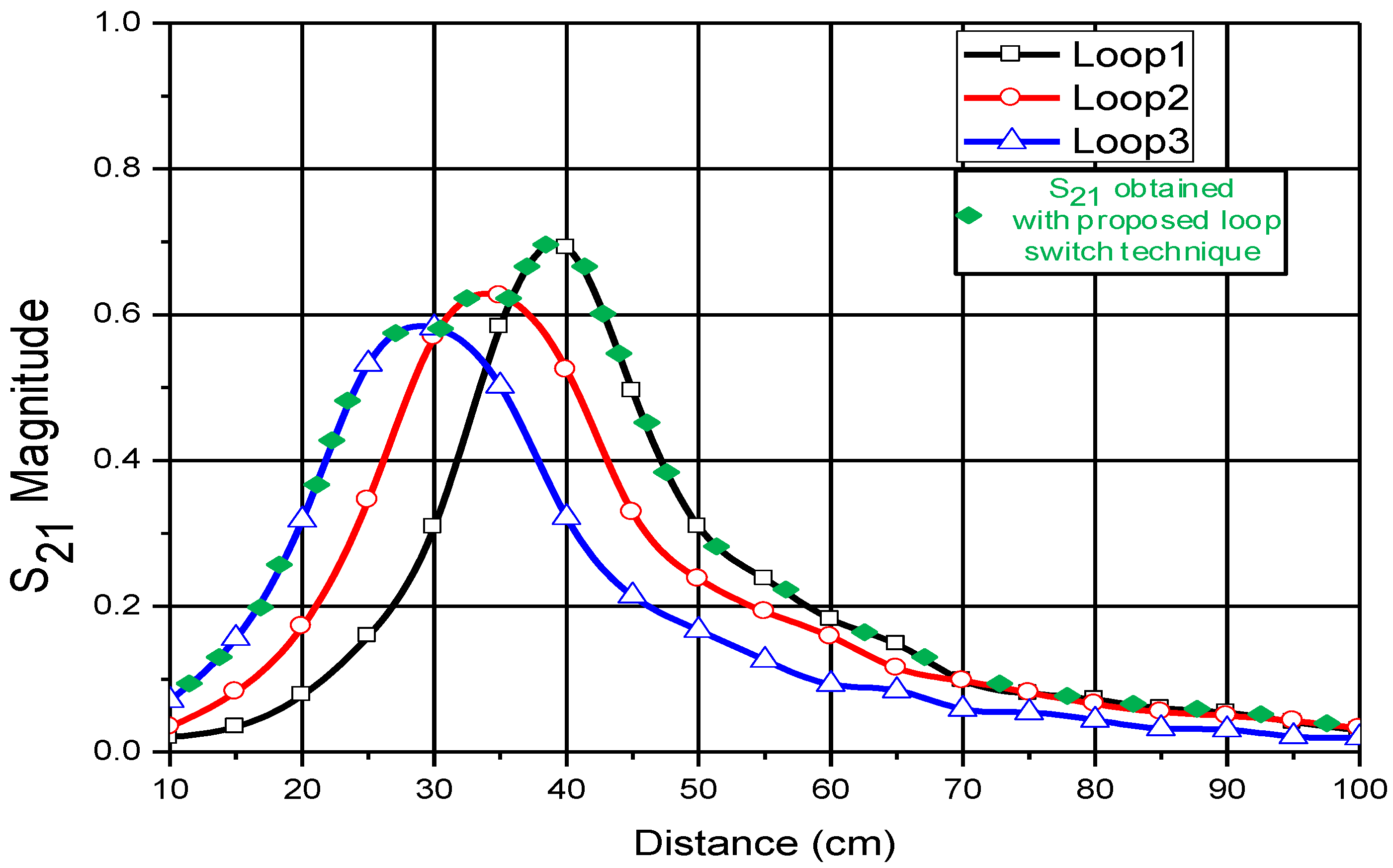
To verify the theoretical conclusions and simulation results, the fabricated system is tested with the aid of a VNA. The S-parameter curves are measured for various
, for Case 1 and Case 2, and the measured efficiency is plotted in
Figure 10 and
Figure 11, respectively. The results indicate that the experimental results closely follow the simulation results for the
curve for varying
. The
Figure 10 and
Figure 11 validate experimentally that the switched loop technique can be effectively used for obtaining maximum power transfer efficiency for varying distances between the transmitter and receiver.
Figure 12 and
Figure 13 show the measured plot of transfer efficiency
versus distance at a fixed frequency of 13.56 MHz for the Case 1 and Case 2 conditions as in
Section 4. The individual loop coil efficiency is plotted along with the transfer efficiency obtained based on the switching loop technique (diamond blocks in green color) for varying
. It can be observed from the plots in
Figure 12 and
Figure 13 that the measured transfer efficiency follows a similar pattern to that of the measured
magnitude depicted in
Figure 10 and
Figure 11. The experimental verification is done in the same manner as the VNA measurements. The receiver side is incrementally moved away from the transmitter side along the WPT systems’ common axis to record the values. An RF power generator with a 50-Ω source resistance supplied 10 Watts of power to the transmitter, which was collected at the receiver equipped with an RF power meter with a 50-Ω load resistance.
For the Case 1 system, from
Figure 12, it is noted that the maximum efficiency (62.6%) is obtained at
= 45 cm, when loop1 is connected to the supply. At
= 20 cm, the maximum efficiency obtained is 16.2 % when loop3 is connected to the supply. For
= 35 cm, loop2 is connected to achieve the maximum efficiency of 49.8%. The power supply is switched to loop1 to obtain high power efficiency for
>37 cm. The experimental results from
Figure 12 indicate that the loop coil switching technique effectively increases the efficiency of the system in comparison to the WPT system consisting of only a single source coil for varying
.
For measurement results in the Case 20-type system, the results from
Figure 13 indicate that higher efficiency for a wide range of
can be obtained. The plot illustrates that a maximum efficiency of 93.3% is obtained for
= 25 cm, when loop3 is switched to the power supply. For
>32 cm and
≤49 cm, the supply source is switched to loop2 to achieve maximum efficiency. For
>52 cm, loop1 is connected to the power source to obtain high efficiency. It is evident from
Figure 12 and
Figure 13 (reference points
= 20 cm: Case 1 efficiency is 16.2%, Case 2 efficiency is 68.4%;
= 60 cm: Case 1 efficiency is 12.8%, Case 2 efficiency is 62.1%) that the two side multiple loop coil switching technique achieves higher transfer efficiency over a wide distance range, in comparison to single-sided multiple loop coil switch technique.
Figure 14 shows the fabricated system for the test.
In the proposed system, loop3 is considered to be more effective for short distances (
Figure 12 and
Figure 13). However, efficiency decreases rapidly after a particular distance (for
>30 cm in
Figure 12 and
>25 cm in
Figure 13) as
deviates from the critical coupling point [
11]. The efficiency also decreases for very short-range distances due to the occurrence of frequency splitting phenomena, as explained in [
11,
21]. The efficiency drops can be minimized by either employing a greater number of loops or utilizing a variable impedance matching network. However, employing an impedance matching network contributes to bulkier systems. Another technique to compensate for the efficiency loss is to adjust the supply frequency at a distance closer than the critical coupling point, so as to restrict the frequency splitting phenomena [
11]. However, this technique is not suitable for implementation in standard systems, as it violates the ISM frequency band. Furthermore, a technique based on varying the
by adjusting the
and
reported in [
13,
18,
19,
20,
21] improved efficiency, but the physical movement of the source and load coils is not feasible for implementation. Accounting for all of these factors, the proposed system proves to be more effective for improvising the efficiency in WPT systems. The implementation of switches in the system is mainly to demonstrate the effectiveness of the system when the system is built for adaptively switching the power to different coils as the distance between the Tx and Rx is varied. In our system, the automatic/adaptive switching algorithm has yet to be implemented.


