Article

Experiment on Bidirectional Single Phase Converter Applying Model Predictive Current Controller

1
Politecnico di Milano, 20156 Milano, Italy
2
Studio Progettazione Informatica Bugliesi (SpiB.it), 20877 Roncello, Italy
*
Author to whom correspondence should be addressed.
Energies 2016, 9(4), 233; https://doi.org/10.3390/en9040233
Submission received: 14 January 2016 / Revised: 4 March 2016 / Accepted: 14 March 2016 / Published: 24 March 2016

Abstract

:
A bidirectional converter able to manage storage is a basic power electronics device, and it is a major component of renewable energy sources, micro grid and also the smart grid concept. In this paper, single-phase bidirectional converter topology is discussed. The state space model has been derived, and a simple model based predictive current controller has been utilized to control the inverter. Control block diagrams have been designed with MATLAB and simulation results are presented and compared with experimental ones, giving credibility to the derived model and the designed control method.

1. Introduction

Increasing global warming and energy consumption demand made it unavoidable to look for new energy sources as alternative to conventional fossil energies [1]. Green and Renewable Energy Sources (RES) have attracted considerable attention in recent decades due to their clean and sustainable nature, in which power electronics play an important role in this road [1]. However, RESs spread around and are available locally. Thus, these Distributed energy Resources (DRs) should be tackled locally wherever those are available by utilizing the proper device. Thus far, DRs and Micro Grids (MG) have come into the picture and are desirable for smart grid functions [2,3]. These applications mostly need proper integration of RES into the grid.
The main concept of integrating RES into the grid and implementing within smart grid systems is to use a bidirectional converter that is able to manage a storage system [3,4]. However, because of intrinsic characteristics of inverters, like low-impedance and quick response [5], their current and voltage profile changes, rapidly, therefore, within a fraction of cycle, those may overload, exceed the current limit and cause failure of the system [5,6]. Thus, capability of the systems is affected by the control and performance of the inverter.
The control of the inverter is an important issue in these kinds of applications because high quality power is desired [7]. Bidirectional inverters are the main parts of applications like Distributed Generation (DG), energy-storage systems, standalone application based on RES and Uninterruptible Power Supplies (UPSs) [8,9].
Several reliable and effective control methods based on classical control algorithms with Pulse Width Modulation (PWM), like conventional Voltage Oriented Control (VOC), Direct Power Control (DPC) [10,11], deadbeat control [12,13], multiloop feedback control [14,15], adaptive control based on bank resonant filters [16], and repetitive-based controllers [17] have been introduced and implemented to industrial applications.
Recent fast development in Microprocessors, Digital Signal Processors (DSP) and Field-Programmable Gate Array (FPGA) has affected power electronics devices deeply. Researchers are continuously looking for fast and more reliable control schemes for complex power electronic devices. Model Predictive Control (MPC) has now roughly three decades of development [10,18], and it is considered one of the biggest advances in converter controls recently [10,19].
Conceptually, MPC can be any control method that predicts the future state of the system by using a model of it, and selection criteria can be involved in optimization functions or not [19]. It appears as an attractive alternative for power electronics applications due to its fast dynamic response.
MPC offers many superior features and can be used in a wide range of applications and process control. It is highly compatible to be implemented in multivariable systems and has been considered one of the best solutions for the nonlinear processes [11,20]. MPC is a very flexible control method for nonlinear systems, and it is highly compatible to include in system constraints [7].
It has been implemented in multilevel cascade H-Bridge Inverter [21,22], Matrix Converter [23,24], UPS [7], and many other wide range power electronic applications [20]. However, it has some drawbacks that should be addressed and compensated [20,25,26].
As reported in several recent works, although MPC has superior performance in transient response, decoupled control and flexibility, it has some drawbacks such as variable switching frequency and wide spectrum. Control methods based on classic Proportional Integral (PI) controllers with PWM have mostly presented a better steady-state performance. Thus, a number of recent works have aimed to deal with these drawbacks and improve the control strategy [20]. However, most works have used discrete model (often for three phase system) with optimization cost function [7,11,15,20,21,22,23]. Due to the nature of MPC, its integration into other types of controllers like PI to improve the inverter performance is difficult.
This paper presents a continuous model and a novel Model based Predictive Current Controller (MPCC) as a current controller a for bidirectional single-phase converter, which is able to manage a storage system. In the voltage source mode, a combination of PI and MPCC (PI-MPCC) is proposed, and advantages of both conventional PI controller and MPCC are utilized to enhance performance and reliability of the system. Simulation and experimental results are presented and compared.
The rest of the paper is organized as follows: Section 2 shows the state space model, Section 3 presents control block diagrams, in Section 4, simulation and experimental results are shown, and, finally, conclusions have been made in Section 5.

2. System Model

Schematic of the implemented bidirectional single phase converter is shown in Figure 1a, and the experimental prototype is shown in Figure 1b. The schematic from top to down, includes the AC side inductance ①; the full bridge Voltage Source Inverter (VSI) with four controlled switches as DC to ac interface ②; the DC bus capacitor ③; the DC chopper leg with two controlled switches in order to manage storage ④; the DC side inductance ⑤ and the storage system ⑥. In order to derive a state space model, controlled variables are shown in the Figure 1a where:
-
X1 stands for output voltage, or grid voltage while it is connected to the grid;
-
X2 represents the inverter current;
-
X3 is the common DC capacitor voltage;
-
X4 is the DC storage current;
-
VB is the storage system voltage, to derive the model for simplicity, and it is considered constant;
-
s1 and s2 are complementary gate signals to derive the IGBT bridge, and those are either zero or one;
-
DBuck and DBoost are not complementary gate signals; to derive the chopper leg, those are either zero or one.
Controlled switches gate signals, according to [27], are modeled by continuous functions and the corresponding variable will be shown by ŝ1, ŝ2, D ^ B u c k and D ^ B o o s t . Thus, to derive the equations and the model, instead of discontinuous zero and one function, the continuous function will be used.
The inverter side model can be driven by Kirchhoff’s Voltage Law (KVL) in loop I and Kirchhoff’s Current Law (KCL) on the DC bus capacitor current Equations (1) and (2).
V s + V L a c s ^ 1 X 3 + s ^ 2 X 3 = 0
i c s ^ 1 X 2 + s ^ 2 X 2 = 0
which, using state space parameters and rewriting the equations, lead to
X 1 + S L a c X 2 = s ^ 1 X 3 s ^ 2 X 3
S C T X 3 = s ^ 1 X 2 s ^ 2 X 2
S stands for Laplace transform parameter, and the complementary properties of ŝ1 and ŝ2 necessitates that: ŝ1 + ŝ2 = 1. Using this property, the inverter model can be simplified.
The DC chopper leg during charge mode works as Buck converter and during the discharge mode as Boost one. Thus, in the model, both modes of operations have been considered, and, for each operation, mode specific equations have to be used. Using the same notation, we can write the KVL of loop II for chopper leg Equation (5).
V B V L d c V s w = 0
where Vsw is defined as switch side equivalent voltage for either Boost and Buck conditions. Replacing the Boost and Buck voltage, Equations (5) and (6) can be rewritten for two different operation modes as reported in Equation (7). Using Laplace transform for inductance voltage, Equation (7) leads to Equation (8) and applying Boost and Buck converter equation, the current balance can be written as reported in Equation (9), where iC is the current through the DC link capacitor. Therefore, voltage and current equations for Boost and Buck converters result in:
BoostBuck
V s w = ( 1 D ^ B o o s t ) X 3 V s w = D ^ B u c k X 3 (6)
V B V L d c ( 1 D ^ B o o s t ) X 3 = 0 V B V L d c D ^ B u c k X 3 = 0 (7)
V B S L D C X 4 ( 1 D ^ B o o s t ) X 3 = 0 V B S L D C X 4 D ^ B u c k X 3 = 0 (8)
i C = S C T X 3 = ( 1 D ^ B o o s t ) i D C S C T X 3 = D ^ B u c k i D C (9)
By Equations (3), (4), (8) and (9), the state space model of the bidirectional converter can be driven. Due to multiplication of time varying switching functions and duty cycles to state variables, it can be considered as Linear Time Varying (LTV) system, and the model can be solved by the proper iteration method. There are two main operation modes for these converters, charging the storage only if it is connected to the grid, and, in this case, the model output is X2 (the inverter current). Discharging the storage supplying loads by using energy stored in the storage where the X1 (the inverter output voltage) is considered as model output. In each case, all independent state variables are computed by duty cycles, D ^ B u c k or D ^ B o o s t and continuous switching functions ŝ1 and ŝ2. The model is shown to understand the converter behavior better, and some equations are used for controller design purpose. The complete model analysis will be addressed in another publication.

3. Control Method

The converter control, as presented in Figure 1a, has two separate parts—chopper leg control and inverter control. These two parts practically are linked together through DC bus capacitor. Two controllers are presented here separately. Chopper and inverter control are based on a modified standard method introducing an MPCC, and the designed control logics are described in subsections that follow. For controller design, some equation from a derived model is adopted for digital implementation.

3.1. Chopper Control

Chopper leg can be managed either to charge the storage or to discharge the storage in order to supply the load.

3.1.1. Charging the Storage

As it is seen from Figure 1a, the battery management leg has two IGBTs, where the midpoint is connected to the batteries’ positive terminal through an inductance. Considering antiparallel diodes of the IGBTs by blocking the low-side switch and controlling the high-side switch, it becomes Buck converter, which can charge the batteries using voltage through DC bus capacitor. Standard battery charging is applied in order to charge the batteries, which is called the Constant Current Constant Voltage (CCCV) method. This technique of battery charging has two modes of charging that depend on batteries’ state of charges—constant current and constant voltage [28]. It charges the batteries until near nominal voltage by inserting constant current. Then, it uses constant voltage, charges the batteries keeping the voltage constant, meanwhile the current goes to zero slowly [28].
For the constant current mode by using the basic principle of Buck converter operation [29], considering the equation (8-Buck) part and using Euler first order approximation instead of Laplace transfer function for the derivative, the voltage balance on inductance for one switching period can be achived by rewriting (8-Buck). Therefore, the duty cycle can be evaluated by the Equation (10).
D B u c k = ( Δ i L D C × L D C T s + V B ) V D C = ( ( i L D C ( k ) i L D C ( k 1 ) ) × L D C T s + V B ) V D C
where iLDC is the DC side inductance current in ampere; k is the number related to time step; LDC is the DC side inductance value in Henry; VB is the instantaneous overall battery voltage in volt; VDC is the inverter DC bus voltage; Ts is the controller sampling time in second, and DBuck is the calculated duty cycle in p.u. Considering the predictive controller, ΔiLDC has to be replaced with the difference between reference current (in our case, the batteries’ nominal current equal to 3A) and measured current. In so doing, Equation (10) changes to Equation (11). The generated duty cycle runs the high-side switch of the chopper leg:
D B u c k = ( ( i r e f i L D C ( k ) ) × L D C T s + V B ) V D C
For constant voltage charging control, since the batteries’ voltage is near nominal, the duty cycle can be considered as Buck converter voltage Equation (6); however, in order to have better control on the absorbed current, a cascade controller is used. The controller schema is shown in Figure 2.
The difference between nominal voltage value and measured voltage is fed to a PI controller, and the output is considered as the current reference, which is used as reference to the constant current controller of Equation (10). In order to have control over the absorbed current, PI (VB) output is limited with upper and lower limits. It is considered as batteries’ charging current, so the max is cut to the batteries nominal charging current. Switching and sampling time of charging mode for DC chopper leg IGBTs are the same as the inverter ones (20 kHz).

3.1.2. Discharging Mode

In the discharge mode, the high-side switch of the DC chopper leg is blocked, and by running the lower switch and means of the antiparallel diode, it works as a Boost converter. During discharging mode, the batteries’ voltage is boosted to a higher value and keeps DC bus voltage constant for inverter functioning to supply the load. During discharging mode, in order to decrease losses and keep the converter at Discontinuous Current operation Mode (DCM), the switching frequency is considered much lower than the inverter one. Control approach is based on cascade PI controller with outer voltage control and inner current controller. The schema is shown in Figure 3.
The second PI output is considered as the duty cycle to run the corresponding switch. First PI, PI (VDC) output is the reference DC current for battery discharging mode. During discharge mode, the battery current can be high and the limit is set corresponding to DC inductance rated value to avoid inductance saturation. PI (IDC) output is the duty cycle for the PWM module, so it is limited to stay below one.

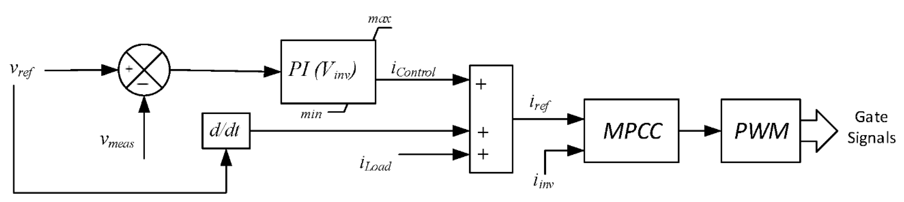
3.2. Inverter Control Method

Inverter control also has two states. When the inverter is connected in parallel to the grid, the inverter terminal voltage is imposed by the grid so the inverter needs to work as the current source. Instead, when the inverter is disconnected from the grid, it should be able to keep its terminal voltage with constant frequency and magnitude under wide load variation. Both states will be discussed below in detail. Indeed, both controllers use a current controller as the latest controller in their loop and this paper used a Model Predictive Current Controller (MPCC) as current controller. Therefore, the MPCC is described before presenting two operational modes controllers. The focus of this study is to manage the inverter properly, so it will be able to follow any current and voltage reference.

3.2.1. Model Predictive Current Controller (MPCC)

The implemented digital MPCC is based on an inverter model, KVL of loop I in Figure 1b. The MPCC is designed based on Equation (1). The Vs and X3 are network voltage and DC bus voltages respectively. Inside the controller, these two variables are real measurments. The VLac and ŝ1 and ŝ2 are unknown so, to calculate switching functions, ŝ1 and ŝ2, it is necessary to estimate VLac. The traditional method to estimate voltage drop on the inductance is using Euler first order approximation for derivative. Therefore, it can be written in the discrete domain as:
v L = Δ i L × L a c T s = ( i L ( k ) i L ( k 1 ) ) × L a c T s
where k is the iteration order, iL(k) and iL(k-1) are inductance currents at corresponding iterations. Lac is the coupling inductance value in Henry and Ts is the iteration step (in this work, it is equal to 50 µs both in simulation and experiment). All the variables in Equation (12) are presented in discrete time domain. In order to control the current in the coupling inductance, it is assumed that the inverter works in a stable condition, and it follows the reference current properly. With this assumption, it is possible to consider the reference current as a prediction for the next iteration step of the inverter current and update Equation (12). Therefore, the current deviation on the inductance can be represented as the difference of reference current and measured current.
Δ i L = i L ( k ) i L ( k 1 ) = i r e f i L ( k )
where the iref is the instantaneous reference current. With this estimation, the voltage drop on the inductance can be predicted by adopting Equation (14) instead of Equation (12). Equation (14) can be replaced in Equation (1) for digital implementation. Rewriting Equation (1) using Equation (14) and using a complimentary property of the inverter continues switching functions, and the continuous inverter switching function can be computed by Equation (15):
v L = ( i r e f i L ( k ) ) × L a c T s
s ^ 1 = ( v s + v D C + v L ) 2 × v D C
The switching function evaluated by Equation (15) ŝ1 and ŝ2 = 1 − ŝ1 are fed to the PWM signal generator to run the IGBT drivers of inverter legs. This MPCC has a fast and reliable response of the model predictive controller, and it also has constant switching frequency due to the PWM technique integration into the control loop. This controller is used in both grid connected and island operation mode controllers.

3.2.2. Grid Connected Mode

During grid connected mode, the full bridge inverter should manage to keep capacitor DC voltage constant to charge the storage, if it is necessary. Depending on the application, the inverter can also be responsible for several tasks like reactive power compensation, harmonic elimination, load sharing, and so on. All control methods, in order to manage reactive current, harmonics and voltage issues, calculate reference current or voltage that the inverter should follow. During the grid connected mode, the device has to work as current source and needs to properly follow a reference current. Figure 4 shows the grid connected operation mode controller block diagram, which is the described MPCC fed to the PWM module of microcontroller.
In this mode, DC bus voltage has been kept constant by using a PI controller. The difference between reference value and measured voltage fed to a PI controller as the error. The output added up to the inverter reference current.

3.2.3. Island Mode

During Island operation mode, the inverter terminal voltage should be controlled as well. Therefore, the inverter voltage PI controller is added in the front end of the described MPCC to design the proposed PI-MPCC. Since inverter current measurement is used for the MPCC inverter current controller, the same measure can therefore be used in the island voltage controller. A control method, based on cascade controller with load current feedback, is implemented in order to avoid voltage drop under load variation for island operation mode [30]. The implemented controller is illustrated in Figure 5.
An ideal sinusoidal waveform with nominal frequency and peak value is considered as the voltage reference, it is compared instantaneously with inverter AC terminal voltage, and the error is fed to a PI controller. The PI (Vinv) output is considered as the control current, and iControl is added to the current reference for the inverter current controller. The limit is set according to AC side inductance current ratio. iControl is added to the load current feedback and the estimated output filter capacitor current, which uses the reference voltage and basic capacitor equation in order to estimate capacitor current. The sum is considered as the reference current. The generated reference current is fed to the inverter MPCC that is explained in Subsection 3.2.1.

4. Results

In order to validate the control method, the derived model and the introduced control method has been implemented and some computer simulations have been developed and compared with the experimental results. To observe inverter stability and performance, the system has been tested under different scenarios.

4.1. System Description

The model has been simulated by using MATLAB SimPowerSystems toolbox. Ideal IGBTs with antiparallel diodes are used to build full bridge inverters. The MPCC explained in Section 3 is used to run the inverter. The inverter rated power is chosen as 3 kW for the experimental setup. Simulated and experimental prototype parameters are listed in Table 1. In order to control the gate signal of IGBTs and run the system in the experimental prototype, Texas Instruments (TI) TMS320F28335 based DSP controller board is used for gate signals, and it is fed through the IGBT driver board. Using TMS320F28335 PWM output signals and also implementing the driver board to run IGBTs inserts proper dead time in order to avoid short circuit on DC bus. The driver board by means of a transformer, guarantees metallic isolation between the power circuit and control board.
The controllers’ set up is reported in Table 2. Controller nomenclatures are as shown in Figure 2, Figure 3 and Figure 5. The saturation limit of controllers are also reported in Table 2.
The performance of the system has been tested under several scenarios both in simulations and experiments, and results are presented together—first, the grid connected mode charging the batteries, and second, island mode, using energy stored in batteries to supply the load. In the grid connected mode, the inverter works as a current source. In Island operation mode, it works as an ideal voltage source using stored energy inside the batteries.

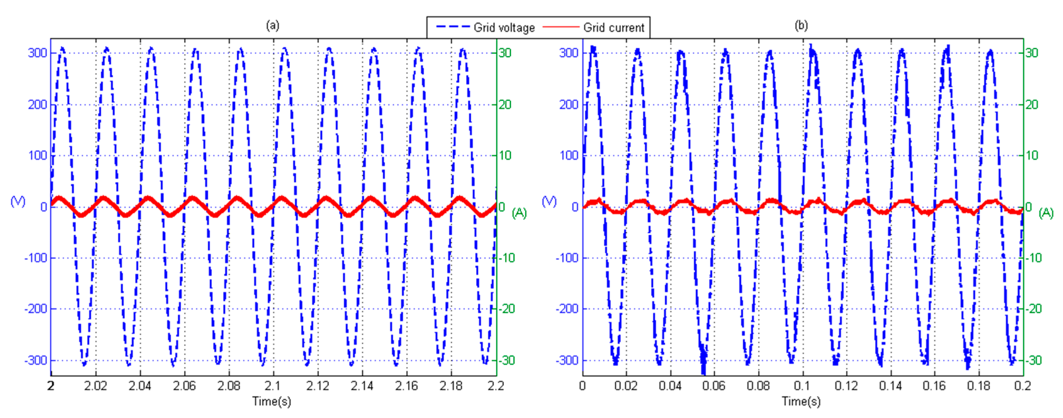
4.2. Scenario I: Grid Connected, No Load

In this configuration, the device is connected in parallel to the grid and it can work as a parallel connected power quality conditioner giving services to the grid and load. Here, the device performance to work in grid connected mode, with no load, is presented. The device just tries to keep the inverter DC bus voltage constant, compensating its losses and supporting the chopper leg to charge the batteries. The chopper leg charges the batteries with constant 3 A at around 80 V so, the inverter absorbs about 1.6 A ac current from network. Simulation results for the grid voltage and grid side current are shown in Figure 6a.
Figure 6b shows the experimental results with no load. The system just manages to charge the batteries. The system absorbs current around 1.7 A rms from the networks, which is equal to batteries nominal charging current at DC 80 V voltage plus the current required to compensate system losses. There is a 0.1 A difference between simulation and experimental results, which could be because of acquisition noises or measurement tool adjustment. Reported experimental data are recorded with differential probes and THD of the voltage is 1.59%, and for the current is equal to 11.80%. The THD analysis for simulation study is much better because, for simulation, the grid voltage is considered as the ideal voltage source (THD = 0), and the control method is also not affected by acquisition noises so the THD of the current from simulation is equal to 4.81%.

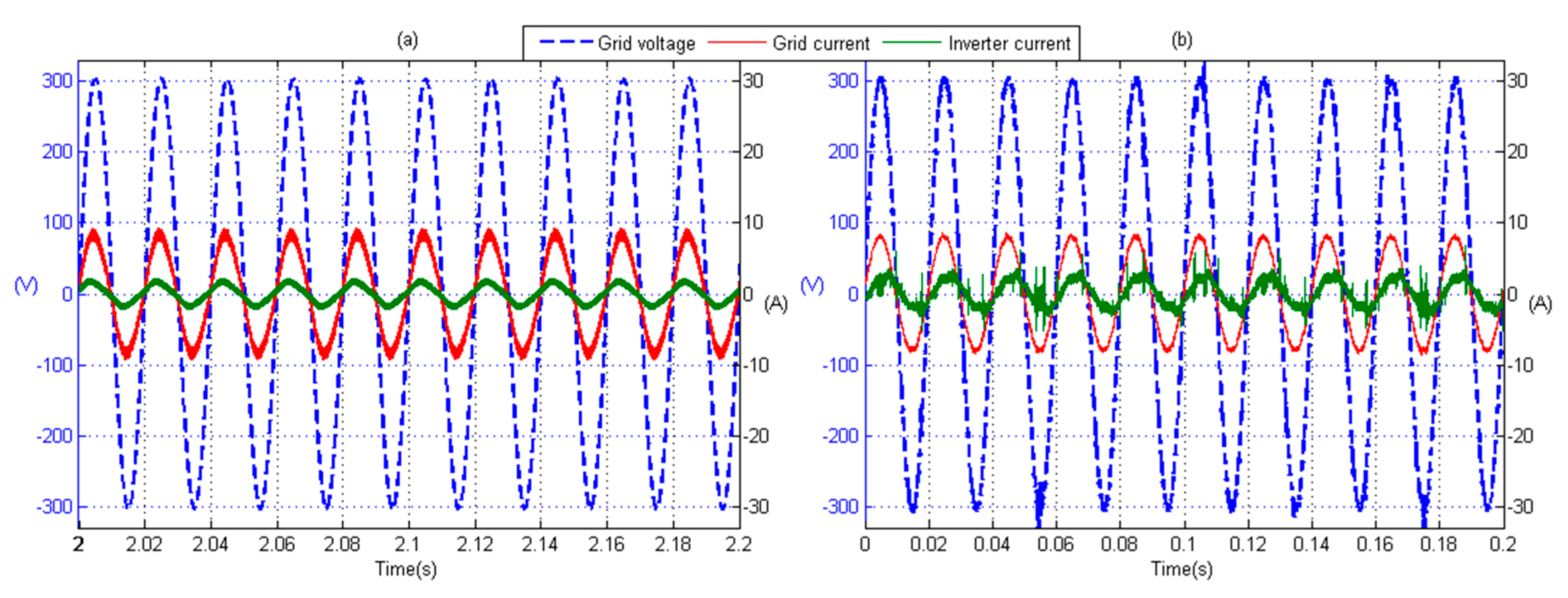
4.3. Scenario II: Grid Connected, 1 kW Resistive Load

As the second illustration, the device is connected to a linear 1 kW resistive load (five 200 W incandescent lamps in experimental test). The grid side current, inverter current and grid voltage from simulation are shown in Figure 7a. At this operation mode, the device can give several services to the load and grid [4]. In this mode, the inverter keeps the DC bus capacitor voltage constant and charges the batteries. In simulation, the grid voltage is considered 215 V to compare with experimental results (during the experimental tests, the grid voltage was 215 V). Thus, the grid absorbs about 5.8 A current. It is the summation of load current and the inverter current. THD results of the simulation are 4.81% and 2.17% for inverter current and grid current, respectively.
Figure 7b shows the experiment’s results. The grid supplies are around 5.7 A rms current, which is the summation of load current and also batteries’ charging current. In this case, experimental results’ THD analysis is 1.48%, 24.52% and 3.01% for grid voltage, inverter current and grid current, respectively. Although the inverter current has a high THD factor, on the grid side, the current and voltage THDs are within standard range.
The difference between simulation and experimental results is again due to acquisition noises, which are apparent in grid voltage and inverter current at Figure 7b and also measurement tools. It can especially be noticed from Figure 7b that the grid current measurement clamp bandwidth is not wide enough to catch switching ripples.

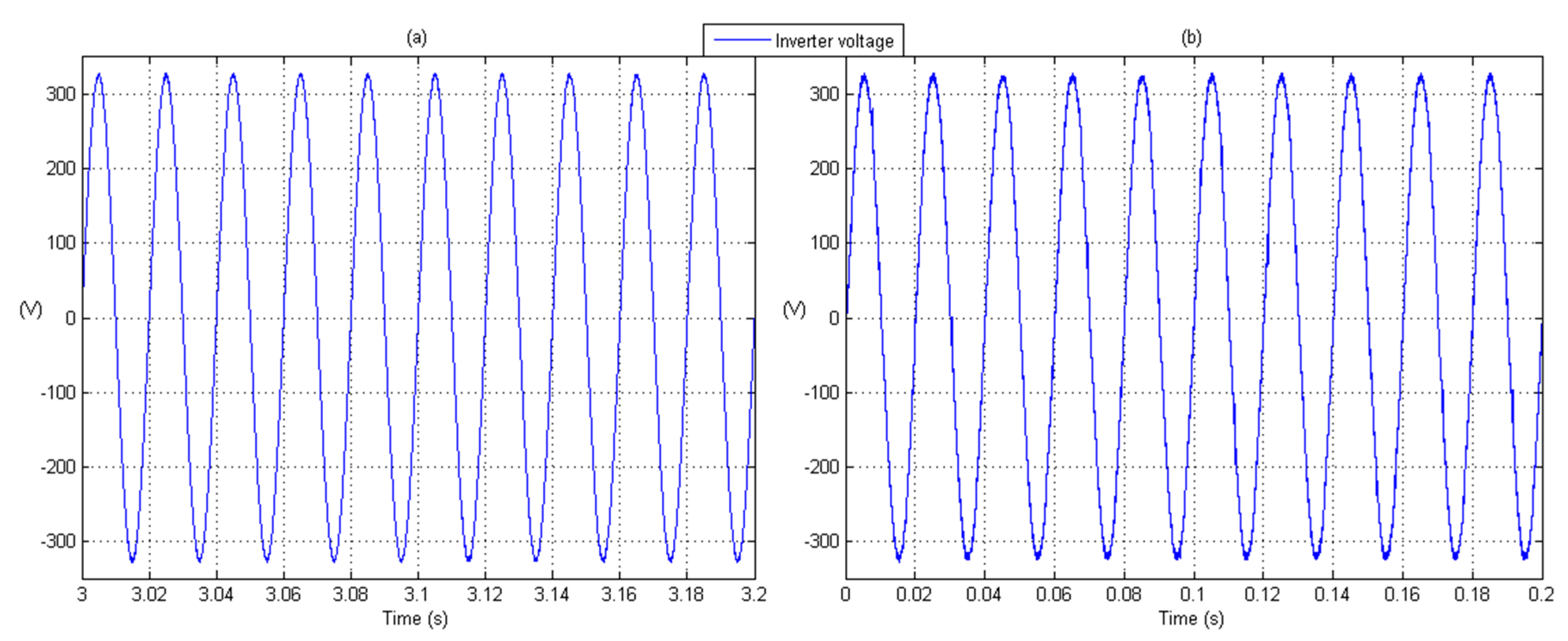
4.4. Scenario III: Island Mode, No Load

The transition from online operation mode to island operation mode is out of the scope of this paper. It is addressed in previous publications [31,32], so it is assumed that the system is working with no load at island operation mode at the steady state. The controllers set up are as reported in Table 2. Simulation results for the voltage at the inverter terminals are shown in Figure 8a. In this operation mode, the inverter uses energy stored in batteries to work as an ideal voltage source. Inverter voltage THD for simulation is 0.46%.
The experimental testbed is also tested in Island operation mode. With no load, the voltage profile is shown in Figure 8b. The inverter keeps output voltage constant with 230 V rms at 50 Hz. THD analysis results for output voltage are equal to 2.29%. Simulation and experimental results are well matched, although, again, the experimental THD is higher than the simulation one due to the reasons that are already addressed.

4.5. Scenario IV: Island Mode, 1 kW Resistive Load

Figure 9b shows the simulated system response in island operation mode under the same 1 kW load. It shows the inverter output voltage and current in steady state condition. The inverter supplies 4.3 A current. The THD analysis of simulation results for the inverter voltage and current are 0.43% and 3.81%, respectively.
The experimental setup is also run in Island mode, supplying 1 kW resistive load (five 200 W incandescent lamps). The results are shown in Figure 9b. The inverter keeps load voltage at a constant 230 V rms, supplying around 4.3 A rms current (same as simulation result). There is phase displacement between load current and voltage because the inverter output passive filter needs reactive power. THD analysis results are 2.28% for inverter voltage and 6.52% for inverter current. It should be noted that voltage differential probes and current clamps are used to record the experimental data. The inverter current is recorded by a DC clamp with low bandwidth (20 kHz) so, the inverter current switching ripples could not be recorded. This is the reason why in Figure 9 the experimental results outperform the simulation ones
Figure 10 shows the transient behavior on DC bus voltage when the load changes from zero to 1 kW. In Figure 10a, the system was working in island mode with no load until t = 3.7 s. At t = 3.7 s, the 1 kW load is connected as the load. As can be seen, there are the voltage drops by a few volts with DC bus voltage. The system is able to recover this voltage drop within less than half a second. This transient response can be much faster, however, the DC battery current absorption is limited inside the controller to avoid any battery damage.
Figure 10b illustrates the experimental setup DC bus voltage response once the 1 kW load is connected to the system. It shows that the system’s response is fast enough to keep DC bus voltage at a set point. The voltage oscillation during the transient compared to simulation results is higher because the simulation is considered an ideal system where there is no acquisition problem and noises. However, in practice, as it can be noticed from Figure 10b, the DC bus has much more noise and oscillation with respect to the simulation one. It is possible to notice the difference between simulation and experimental results in Figure 10b, because, in this case, the voltage probe has higher 30–40 MHz bandwidth. The results are meant to show steady state performance, and the transient behavior was not focused on in this paper.

5. Conclusions

Simple MPCC, utilizing advantages of the conventional PI controller, has been designed for a single phase bidirectional converter. With the proposed PI-MPCC controller variable, the switching function of the original MPC is improved. Moreover, the optimization cost function can be easily adopted to the controller based on the application. The converter is the basic component of most renewable energy types and a major part of the micro grid and smart grid concept. The control method has been tested both in MATLAB simulation environment and with a 3 kW experimental prototype. Results show that the inverter has very good transient and steady state performance. The system has been tested both in grid connected and island operation mode. The inverter simulation model matches very well to the prototype performance.

Acknowledgments

The research leading to these results has received funding from the Italian Ministry of Economic Development (project Smart Domo Grid).

Author Contributions

In this research activity, all the authors were equally involved in the system analysis and design, simulation, results analysis and discussion, and manuscript preparation. All authors have approved the submitted manuscript.

Conflicts of Interest

The authors declare no conflict of interest.

Abbreviations

The following abbreviations are used in this manuscript:
RES
Renewable Energy Sources
DR
Distributed Resources
MG
Micro Grids
DG
Distributed Generation
UPS
Uninterruptible Power Supplies
PWM
Pulse Width Modulation
VOC
Voltage Oriented Control
DPC
Direct Power Control
DSP
Digital Signal Processors
FPGA
Field-Programmable Gate Array
MPC
Model Predictive Control
PI
Proportional Integral
MPCC
Model Predictive Current Controller
PI-MPCC
PI and MPCC
KVL
Kirchhoff’s Voltage Law
KCL
Kirchhoff’s Current Law
VSI
Voltage Source Inverter
CCCV
Constant Current Constant Voltage
DCM
Discontinuous Current operation Mode
TI
Texas Instruments
LTV
Linear Time Varying

References

  1. Bose, B.K. Global warming: Energy, environmental pollution, and the impact of power electronics. IEEE Ind. Electron. Mag. 2010, 4, 6–17. [Google Scholar] [CrossRef]
  2. Karimi-Ghartemani, M. Universal integrated synchronization and control for single-phase DC/AC converters. IEEE Trans. Power Electron. 2015, 30, 1544–1557. [Google Scholar] [CrossRef]
  3. Accetta, G.; Della Giustina, D.; D’Antona, G.; Faranda, R.; Zanini, S. SmartDomoGrid: Reference architecture and use case analyses for a grid-customer interaction. In Proceedings of the 4th IEEE European Innovative Smart Grid Technologies (ISGT) Conference, Copenhagen, Danmark, 6–9 October 2013; pp. 1–4.
  4. Accetta, G.; D’Antona, G.; Della Giustina, D.; Hafezi, H.; Faranda, R. Open UPQC: A possible solution for customer power quality improvement. Shunt unit analysis. In Proceedings of the 16th IEEE International Confrence on Harmonics and Quality of Power, ICHQP, Bucharest, Romania, 25–28 May 2014; pp. 596–600.
  5. Kawabata, T.; Higashino, S. Parallel operation of voltage source inverters. IEEE Trans. Ind. Appl. 1988, 24, 281–287. [Google Scholar] [CrossRef]
  6. Walling, R.A.; Saint, R.; Dugan, R.C.; Burke, J.; Kojovic, L.A. Summary of distributed resources impact on power delivery systems. IEEE Trans. Power Del. 2008, 23, 1636–1644. [Google Scholar] [CrossRef]
  7. Cortes, P.; Ortiz, G.; Yuz, J.I.; Rodriguez, J.; Vazquez, S.; Franquelo, L.G. Model predictive control of an inverter with output LC filter for UPS applications. IEEE Trans. Ind. Electron. 2009, 56, 1875–1883. [Google Scholar] [CrossRef]
  8. Carrasco, J.M.; Franquelo, L.G.; Bialasiewicz, J.T.; Galvan, E.; PortilloGuisado, R.C.; Prats, M.A.M.; Leon, J.I.; Moreno-Alfonso, N. Power-electronic systems for the grid integration of renewable energy sources: A survey. IEEE Trans. Ind. Electron. 2006, 53, 1002–1016. [Google Scholar] [CrossRef]
  9. Blaabjerg, F.; Teodorescu, R.; Liserre, M.; Timbus, A.V. Overview of control and grid synchronization for distributed power generation systems. IEEE Trans. Ind. Electron. 2006, 53, 1398–1409. [Google Scholar] [CrossRef]
  10. Parvez Akter, M.D.; Mekhilef, S.; Nadia, M.L.T.; Akagi, H. Model predictive control of bidirectional AC-DC converter for energy storage system. J. Electr. Eng. Technol. 2015, 10, 165–175. [Google Scholar] [CrossRef]
  11. Kouro, S.; Cortés, P.; Vargas, R.; Ammann, U.; Rodríguez, J. Model predictive control—A simple and powerful method to control power converters. IEEE Trans. Ind. Appl. 2009, 56, 1826–1838. [Google Scholar] [CrossRef]
  12. Kojima, M.; Hirabayashi, K.; Kawabata, Y.; Ejiogu, E.C.; Kawabata, T. Novel vector control system using deadbeat-controlled PWM inverter with output LC filter. IEEE Trans. Ind. Appl. 2004, 40, 162–169. [Google Scholar] [CrossRef]
  13. Mattavelli, P. An improved deadbeat control for UPS using disturbance observers. IEEE Trans. Ind. Electron. 2005, 52, 206–212. [Google Scholar] [CrossRef]
  14. Loh, P.C.; Newman, M.J.; Zmood, D.N.; Holmes, D.G. A comparative analysis of multiloop voltage regulation strategies for single and three-phase UPS systems. IEEE Trans. Power Electron. 2003, 18, 1176–1185. [Google Scholar]
  15. Buso, S.; Fasolo, S.; Mattavelli, P. Uninterruptible power supply multiloop control employing digital predictive voltage and current regulators. IEEE Trans. Ind. Appl. 2001, 37, 1846–1854. [Google Scholar] [CrossRef]
  16. Marwali, M.N.; Keyhani, A. Control of distributed generation systems—Part I: Voltages and currents control. IEEE Trans. Power Electron. 2004, 19, 1541–1550. [Google Scholar] [CrossRef]
  17. Escobar, G.; Mattavelli, P.; Stankovic, A.M.; Valdez, A.A.; Leyva-Ramos, J. An adaptive control for UPS to compensate unbalance and harmonic distortion using a combined capacitor/load current sensing. IEEE Trans. Ind. Electron. 2007, 54, 839–847. [Google Scholar] [CrossRef]
  18. Lee, J.H. Model predictive control: Review of the three decades of development. Int. J. Control Autom. Syst. 2011, 9, 415–424. [Google Scholar] [CrossRef]
  19. D’Antona, G.; Faranda, R.; Hafezi, H.; Bugliesi, M. Experiment on bidirectional single phase converter applying simple model predictive control. In Proceedings of the 2015 IEEE 15th International Conference on Environment and Electrical Engineering (EEEIC), Rome, Italy, 10–13 June 2015; pp. 1019–1024.
  20. Rodriguez, J.; Kazmierkowski, M.; Espinoza, J.; Zanchetta, P.; Abu-Rub, H.; Young, H.; Rojas, C.A. State of the art of finite control set model predictive control in power electronics. IEEE Trans. Power Electron. 2013, 9, 1003–1016. [Google Scholar] [CrossRef]
  21. Cortes, P.; Wilson, A.; Kouro, S.; Rodriguez, J.; Abu-Rub, H. Model predictive control of multilevel cascaded H-bridge inverters. IEEE Trans. Ind. Electron. 2010, 57, 2691–2699. [Google Scholar] [CrossRef]
  22. Vahedi, H.; Al-Haddad, K.; Labbe, P.-A.; Rahmani, S. Cascaded multilevel inverter with multicarrier PWM technique and voltage balancing feature. In Proceedings of the IEEE 23rd International Symposium on Industrial Electronics (ISIE), Istanbul, Turkey, 1–4 June 2014; pp. 2155–2160.
  23. Rivera, M.; Wilson, A.; Rojas, C.A.; Rodriguez, J.; Espinoza, J.R.; Wheeler, P.W.; Empringham, L. A comparative assessment of model predictive current control and space vector modulation in a direct matrix converter. IEEE Trans. Ind. Electron. 2013, 60, 578–588. [Google Scholar] [CrossRef]
  24. Rmili, L.; Rahmani, S.; Vahedi, H.; Al-Haddad, K. A comprehensive analysis of matrix converters: Bidirectional switch, direct topology, modeling and control. In Proceedings of the IEEE 23rd International Symposium on Industrial Electronics (ISIE), Istanbul, Turkey, 1–4 June 2014; pp. 313–318.
  25. Cortes, P.; Rodriguez, J.; Silva, C.; Flores, A. Delay compensation in model predictive current control of a three-phase inverter. IEEE Trans. Ind. Electron. 2012, 59, 1323–1325. [Google Scholar] [CrossRef]
  26. Xia, C.; Wang, M.; Song, Z.; Liu, T. Robust model predictive current control of three-phase voltage source PWM rectifier with online disturbance observation. IEEE Trans. Ind. Inf. 2012, 8, 459–471. [Google Scholar] [CrossRef]
  27. Hafezi, H.; Akpinar, E.; Balikci, A. Cascade PI Controller for Single-phase STATCOM. In Proceedings of the 16th International Power Electronics and Motion Control Confrence and Exposition, PEMC, Antalya, Turkey, 21–24 September 2014; pp. 127–132.
  28. Carmeli, M.S.; Castelli Dezza, F.; Faranda, R.; Marchegiani, G.; Mauri, M. Universal digital controller for power quality and distributed generation systems. In Proceedings of the International Symposium on Power Electronics, Electrical Drives, Automation and Motion, SPEEDAM, Taormina, Italy, 23–26 May 2006; pp. 508–513.
  29. Mohan, N.; Undeland, T.M.; Robbins, W.P. Power Electronics: Converters, Applications, and Design, 2nd ed.; Wiley: New York, NY, USA, 1995. [Google Scholar]
  30. Ho, W.-J.; Lio, J.-B.; Feng, W.-S. Economic UPS structure with phase-controlled battery charger and input-power-factor improvement. IEE Proc. Electr. Power Appl. 1997, 144, 221–226. [Google Scholar] [CrossRef]
  31. Castelli Dezza, F.; Faranda, R.; Mazzucco, I.; Redi, P.; Tironi, E. An interface converter for DG/storage system able to improve Power Quality of the load. In Proceedings of the IEEE Power Engineering Society General Meeting PES, Montreal, QB, Canada, 18–22 June 2006.
  32. D’Antona, G.; Della Giustina, D.; Faranda, R.; Hafezi, H. Open UPQC Power Quality Manager within Distributed Generation Systems. In Proceedings of the IEEE 10th International Symposium on Diagnostics for Electrical Machines, Power Electronics and Drives (SDEMPED), Guarda, Portugal, 1–4 September 2015; pp. 501–507.
Figure 1. Bidirectional converter (a) schematic and (b) prototype.
Energies 09 00233 g001
Figure 2. Constant voltage chopper charging controller—PI-MPCC, chopper.
Energies 09 00233 g002
Figure 3. Chopper Discharging controller.
Energies 09 00233 g003
Figure 4. Grid connected mode controller block diagram.
Energies 09 00233 g004
Figure 5. Island mode controller block diagram—PI-MPCC, inverter.
Energies 09 00233 g005
Figure 6. Grid connected inverter response—no load, (a) Simulation; (b) Experiment.
Energies 09 00233 g006
Figure 7. Grid connected inverter response—1 kW resistive load, (a) Simulation; (b) Experiment.
Energies 09 00233 g007
Figure 8. Island operation mode—no load, (a) Simulation; (b) Experiment.
Energies 09 00233 g008
Figure 9. Island operation mode, inverter response—1 kW resistive load, (a) Simulation; (b) Experiment.
Energies 09 00233 g009
Figure 10. Island operation mode, DC bus transient response—1 kW resistive load, (a) Simulation; (b) Experiment.
Energies 09 00233 g010
Table 1. Single phase bidirectional converter parameters.
Grid Nominal Voltage230 V rms
Nominal frequency50 Hz
Storage voltage80 V
DC bus voltage450 V
DC bus capacitor C3 parallel 6800 µF
DC side switching inductance L1 mH
ac side switching inductance L1 mH
Inverter output filter10 µF
Max power switches (IGBT)195 A
Batteries12 V, 12 Ah, Sealed Lead-Acid
Sampling time10 µs
Table 2. Bidirectional converter controller set up.
kpkiOutput Saturation
ItemMaxMin
PI (VB)0.535IDC_ref3 A0 A
PI (VDC)325IDC_ref45 A0 A
PI (IDC)1250Duty cycle0.950
PI (Vinv)0.743000IControl35 A−35 A

