Article

New Scheme for Seamless Operation for Stand-Alone Power Systems

Department of Electrical Engineering, Myong-ji University, 116 Myongji-ro, Yongin-si, Gyeonggi-do 449-728, Korea
*
Author to whom correspondence should be addressed.
Energies 2016, 9(6), 457; https://doi.org/10.3390/en9060457
Submission received: 21 April 2016 / Revised: 31 May 2016 / Accepted: 1 June 2016 / Published: 15 June 2016
(This article belongs to the Collection Smart Grid)

Abstract

:
On remote islands photovoltaic (PV) panels with battery energy storage systems (BESSs) supply electric power to customers in parallel operation with engine generators (EGs) to reduce fuel consumption and environmental burden. A BESS operates in voltage control mode when it supplies power to loads alone, while it operates in current control mode when it supplies power to loads in parallel with the EG. This paper proposes a smooth mode change of the BESS from current control to voltage control by using initial value at the output of integral part in the voltage controller, and a smooth mode change from voltage control to current control by tracking the EG output voltage to the BESS output voltage using a phase-locked loop (PLL). The feasibility of the proposed scheme was verified through computer simulations and experiments with a scaled prototype.

1. Introduction

Recently, many projects to install photovoltaic (PV) panels and battery energy storage systems (BESSs) on remote islands have been implemented in many countries to save fuel and to reduce environmental burden by primarily supplying electric power using PV panels and BESSs, and supplying additionally required electric power through complementary operation of engine generators (EGs) connected in parallel.
In this system, the electric power obtained from PV panels is generally charged in the BESS and the charged electric power is supplied to loads first to save the EG operation. If the electric power supplied by the BESS is less than the electric power required by the loads, then the EG connected in parallel is operated to cover the electric power shortage. If the electric power required by the loads decreases and can be supplied by the BESS alone, then the EG will be separated from the network. When the EG has been connected in parallel with a BESS, the EG operates to control the voltage and frequency of the system and the BESS operates in the current control mode. However, when the EG has been separated, the BESS operates in the voltage control mode to control the voltage and frequency of the system [1,2].
Therefore, if the EG that has been operated in parallel with the BESS is separated because of load reduction, the mode of BESS operation should be quickly changed from current control to voltage control. If the load increases, the EG should be activated again and begin to control the voltage and frequency after achieving synchronization with the BESS, and the latter should quickly change the operation from voltage control to current control. The operation changes from voltage control to current control and from current control to voltage control should be carried out without excessive transient phenomena, so that no interruption in the electric power supply to the loads occurs [3,4,5].
To carry out stable mode changes, indirect current control techniques have been studied recently [6,7]. However, this technique brings about severe transients in the case of single-phase currents because instantaneous current cannot be controlled, and control models cannot be easily obtained in the case of three-phase currents, because nonlinear functions are involved in creating voltage command values and the amount of calculations is large because the control structure is more complicated.
A capacitor voltage controller that was defied in [8] was designed using existing control theory by tracking the sine and cosine tables in the control block. However, the magnitude and phase angle of capacitor voltage can be tracked by using the generator inductance, so accurate inductance values must be known and dynamic characteristics are highly dependent on the inductance variation.
In [9] an accurate control model was proposed, in which power quality improvement was achieved by indirect current control. However, this method has the disadvantage of needing to know the accurate coupling inductance to the power system. A simple change of reference voltage was proposed in [10] which only focused on the voltage control issue of the grid-tied single-phase inverter.
In [11,12] a seamless transition sequence was precisely expressed. However, inverter voltage and grid current could experience unstable situations because the grid current has a value unequal to the voltage control output. A cascaded current-voltage control was proposed in [13] for improving the power quality of loads. However, this method was concentrated on reducing the total harmonic distortion (THD) of load voltage and current, and not concentrated on the seamless operation.
In addition, mode change methods using droop control have also been proposed [14,15]. However, these methods have drawbacks such as their slow dynamic characteristics due to the droop operation and limited maximum output due to the inability of achieving discrete current control.
A multi-loop voltage controller that includes a capacitor differential voltage feedback loop and an internal reference voltage feed-forward path was proposed in [16] for maintaining the operation voltage and reducing the transient response time. However, this method brings about an output voltage distortion regardless of any sudden voltage changes due to mode transition.
Both the current controller and the feed-forward voltage controller for a seamless mode transfer from grid-connected to islanding modes under an overvoltage condition are proposed in [17]. However, the seamless transfer strategy from the islanding to grid-connected mode is not described, and the active and reactive load powers are required when a reference grid current is calculated from the reference output voltage.
To supplement the drawbacks of the existing mode change schemes, this paper presents a new scheme to add initial values to the output of integral control in the voltage controller to enable smooth mode changes from current control to voltage control. The proposed scheme has the following advantages over the previously proposed schemes: first, it does not require complicated equations to achieve seamless operation; second, unlike indirect current control, the proposed scheme has stable and fast dynamic characteristics by using a conventional cascade control method without an additional controller. In addition, the output voltage of the EG was made to follow the output voltage of the BESS and to match the level and phase for smooth mode change when the EG is reconnected.

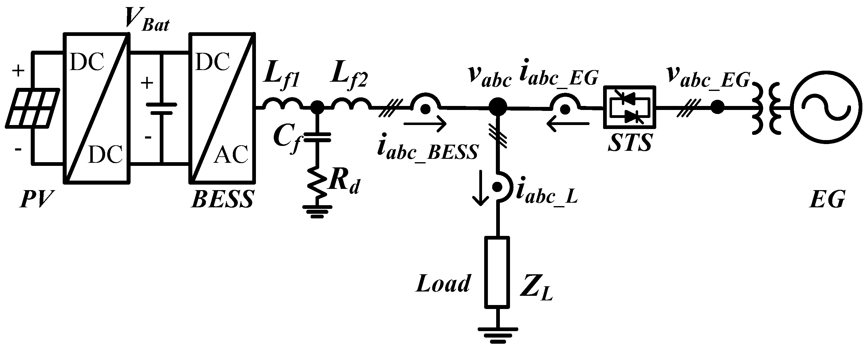
2. System Configuration and Control Scheme

Figure 1 shows a basic configuration of a stand-alone electric power system installed on a remote island. During the daytime on sunny days, the electric power produced by PV panels is charged to the BESS through a direct current to direct current (DC-DC) converter and supplied to loads through a direct current to alternating current (DC-AC) inverter. The EG is connected to the BESS in parallel and operates only when the remaining charged capacity of the BESS is not sufficient. Therefore, this system has the advantage of minimizing the use of the EG to save fuel and mitigate the environmental burden.
Because the inverter’s alternating current (AC) output voltage contains some harmonics, an output filter is installed between the inverter and the load. The EG is connected through a transformer and a solid-state transfer switch (STS) that is composed of back-to-back connected thyristor switches.
To implement the proposed seamless operation, the output voltage and current of the BESS, the voltage and current of the load, and the voltage and current of the EG at the STS were measured.

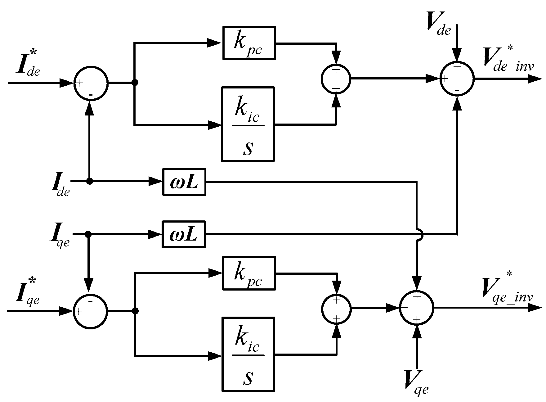
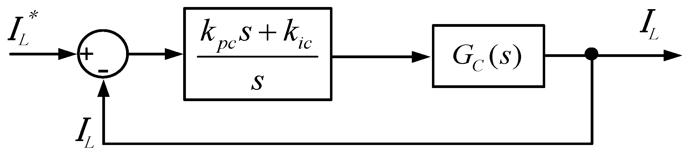
2.1. Current Control during Parallel Operation

The current and voltage of the BESS are controlled on the synchronous reference frame. The three-phase voltage and current measured through the sensors are converted into direct current components through the static and rotating reference frame transformations described in Equations (1) and (2), respectively:
[ f d s f q s ] = 2 3 [ 1 1 2 1 2 0 3 2 3 2 ] [ f a f b f c ]
[ f d e f q e ] = [ cos θ sin θ sin θ cos θ ] [ f d s f q s ]
Figure 2 shows the current controller of the BESS using a PI control. To remove the coupled components between the d-axis current and the q-axis current, the mutually coupled components were compensated in the control output. The load voltages V d e and V q e were separately compensated to improve the dynamic characteristics of the system [18]. The reference voltages V d e _ i n v * and V q e _ i n v * of the BESS outputted through current control are expressed by Equation (3):
V d e _ i n v * = ( k p c + k i c s ) ( I d e * I d e ) ω L I q e + V d e V q e _ i n v * = ( k p c + k i c s ) ( I q e * I q e ) + ω L I d e + V q e
The current controller has function of controlling active power P and reactive power Q. The active power and the reactive power can be expressed with respect to the current and voltage on the rotating reference frame as shown by Equation (4):
P = 1.5 ( V d e I d e + V q e I q e ) Q = 1.5 ( V d e I q e V q e I d e )
where V d e and V q e represent three-phase voltages on the synchronous reference frame, I d e and I q e represent three-phase currents on the synchronous reference frame.
If the PLL of the load voltage operates in normal condition, the active power can be expressed by the d-axis component current and the reactive power can be expressed by the q-axis component current. Therefore, the reference value for current control can be obtained from the base power:
I d e * = P r e f 1.5 V d e , I q e * = Q r e f 1.5 V q e

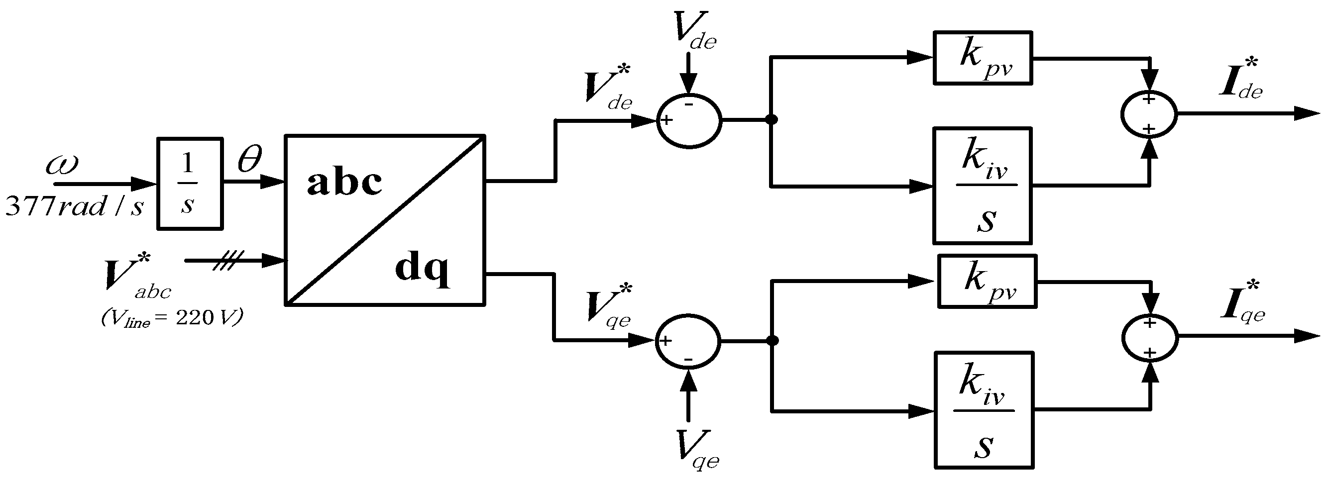
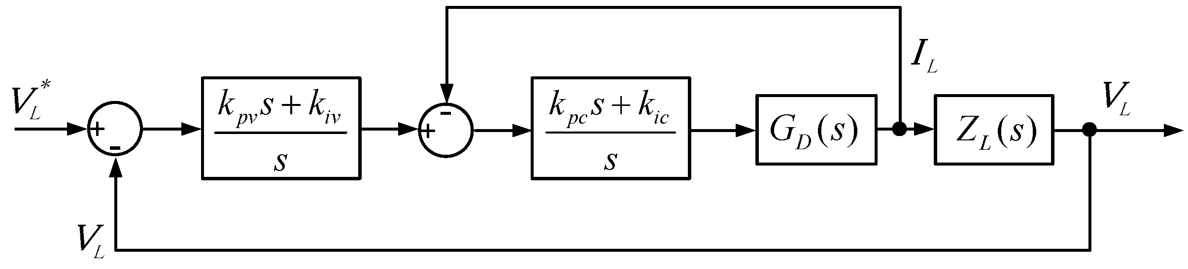
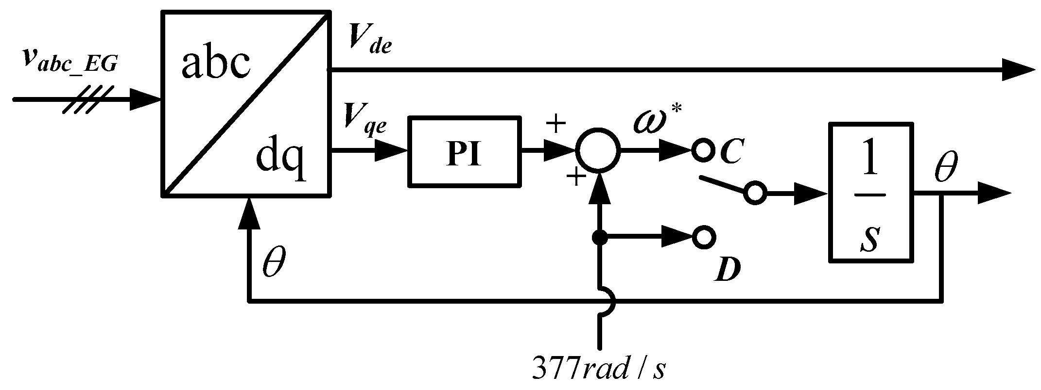
2.2. Voltage Control during Separate Operation

If the EG that has been operated in parallel is separated, the load voltage cannot be maintained constant. Therefore, the BESS will perform voltage control on behalf of the EG. The BESS will constantly control the frequency at 60 Hz and the line-to-line voltage at 220 V. Since the phase-A voltage should be outputted at 180 V to generate the line-to-line voltage constantly at 220 V, the reference voltage V d e * is set to 180 V and the reference voltage V q e * is set to 0 V.
Figure 3 shows the configuration of the voltage controller. The d-axis and q-axis components of the reference voltage are compared with the actually measured values and the differences are entered into the proportional integral (PI) controller to obtain the reference currents I d e * and I d e * .
The reference current generated as the output of the voltage controller is supplied as the input of the current controller shown in Figure 2. Therefore, the voltage controller operates in a double loop control mode. In this double loop control method, not only is the voltage controlled but also the current is controlled indirectly so that sudden changes in the current do not occur and the system can operate stably.

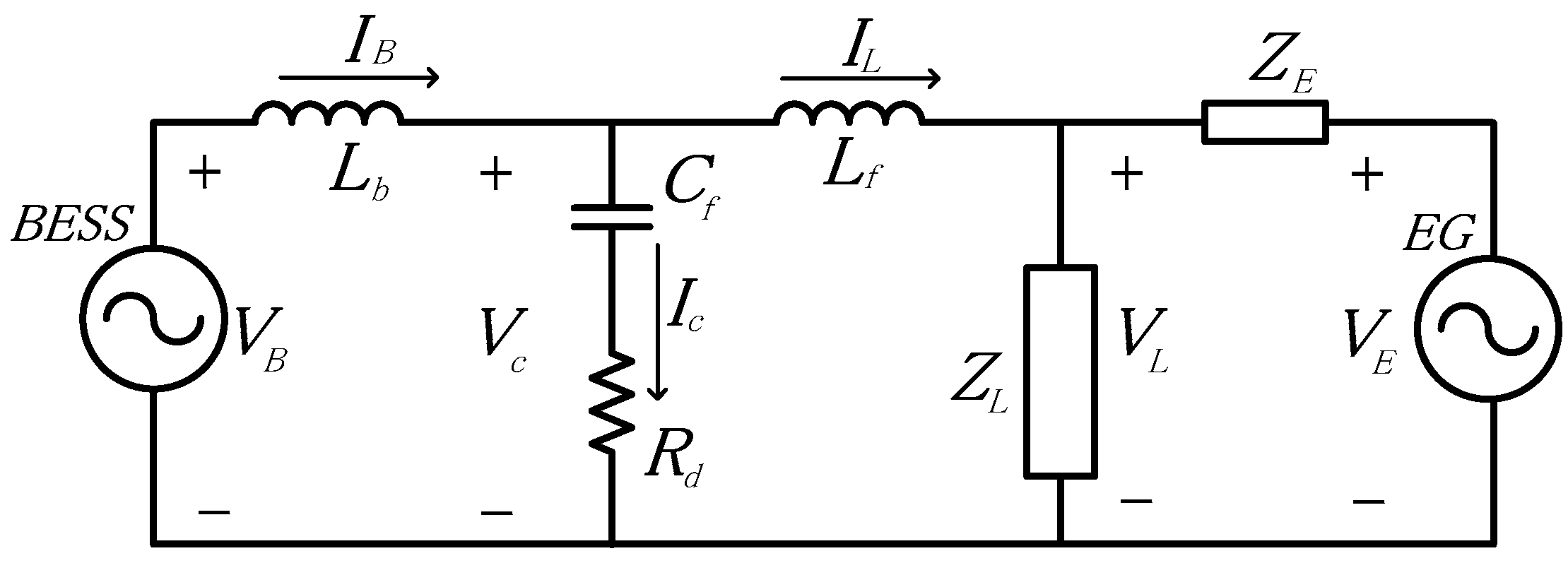
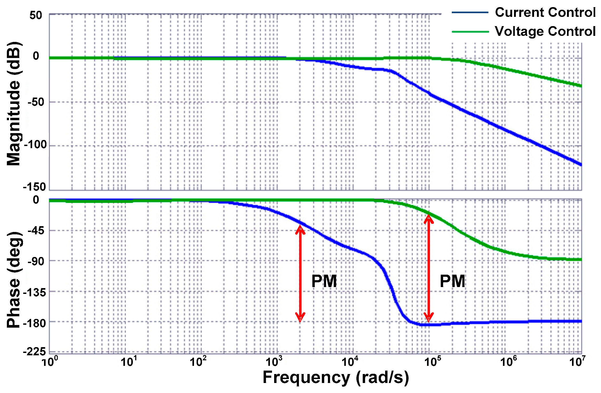
3. Operation Stability Analysis
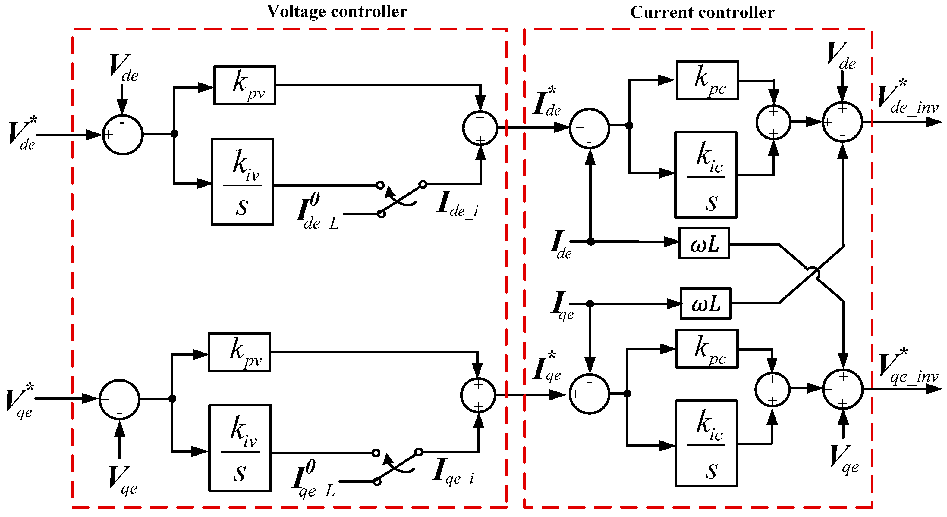
Figure 4 shows the equivalent circuit for the entire system including the BESS, LCL filter, load, and EG. To analyze the stability of the control system for the EG’s connected mode and disconnected mode, transfer functions were derived for both voltage control and current control. Since normally the BESS supplies electric power to loads and the EG operates as a backup power supply, it was assumed that no reverse current would flow to the EG in any event. In addition, the EG was assumed to be connected to loads through a transformer with leakage inductance.
The circuit parameters that are used in the equivalent circuit are defined as follows:
  • V B , BESS output voltage; I B , BESS output current; L b , BESS inverter reactor; V C , Filter capacitor voltage; I C , Filter capacitor current; C f , Filter capacitor; R d , Damping resistor; L f , Filter reactor; V L , Load voltage; I L , Load current; Z L , Load impedance; V E , Engine generator voltage; Z E , Engine generator impedance.
In connected operation, if Kirchhoff’s voltage and current laws are applied, Equations (6)–(8) will be derived, as described in [19]:
I B = 1 L b s ( V B V C )
V C = 1 + C f R d s C f s ( I B I L )
I L = V C V L s L f
In order to derive the current control scheme, it is assumed that Z E is much smaller than Z L . Then I L can be expressed as follows:
I L V C s L f
If the above three Equations (6), (7) and (9) are solved simultaneously and organized into a transfer function G C ( s ) with respect to I L and V B , Equation (10) can be derived:
G C ( s ) = C f R d s + 1 L b L f C f s 3 + ( L b + L f ) C f R d s 2 + ( L b + L f ) s
The block diagram for closed-loop current controller using Equation (10) can be shown in Figure 5. In this block diagram, k p c is the proportional gain of the current controller and k i c is the integral gain of the current controller.
In disconnected operation, the EG is separated from the load and the BESS carries out voltage control. Since the load voltage V L is controlled by the BESS, not by the EG, it will affect the transfer function. Thus a transfer function for I L can be derived again as shown in Equation (11):
I L = 1 L f s ( V C V L )
Using Equations (6), (7) and (11), a transfer function GD(s) in the disconnected operation can be derived by Equation (12):
G D ( s ) = C f R d s + 1 L b L f C f s 3 + C f ( L b + L b R d + L f R d ) s 2 + ( C f R d + L b + L f ) s + 1
The block diagram for closed-loop voltage controller using Equation (12) can be shown using double loop control as presented in Figure 6. In Figure 6, k p v is the proportional gain of the voltage controller and k i v is the integral gain of the voltage controller. In addition, Z L ( s ) represents the load impedance and V L represents the load voltage. Since the BESS performs load voltage control, the final output is the load voltage V L .
Figure 7 shows the Bode diagrams for the current control transfer function and voltage control transfer function. The gains of current control are k p c = 10, k i c = 800 and the gains of voltage control are k p v = 1 and k i c = 5. Assuming that the load had a constant capacity, an R L (R = 10 Ω, L = 3 mH) circuit was used. On reviewing these Bode diagrams, it can be seen that the current controller and the voltage controller have sufficient phase margins so that the control is stable.

4. Proposed Seamless Operation

4.1. Mode Change into Separate Operation

Since the BESS is only operated in current control mode during the connected operation, the integral value of the voltage controller is always 0 and that the individual phases of the three-phase load voltage are balanced, the load current can be expressed by the DC components of d-axis and q-axis I d e _ L and I q e _ L on the synchronous reference frame.
The load currents I d e _ L , I q e _ L expressed on the synchronous reference frame are respectively the sum of the d-axis and q-axis currents I d e _ E G , I q e _ E G and the d-axis and q-axis currents I d e _ B E S S , I q e _ B E S S as shown in Equation (13):
I d e _ L = I d e _ E G + I d e _ B E S S I q e _ L = I q e _ E G + I q e _ B E S S
Since I d e _ E G , I q e _ E G are equal to 0 immediately after the separation of the EG, the load currents I d e _ L , I q e _ L will decrease and the load voltages will also decrease accordingly. Therefore, to recover the load voltage, the amount of electric power supplied from the EG to the load should be additionally supplied by the BESS. For the BESS to recover the normal load voltage through voltage control, a certain amount of transient time is taken immediately after the mode change. Since this transient time is determined by the accumulated value of the integral gains in the voltage controller, the transient time can be reduced by appropriately adjusting the integral gains. However, if the integral gains are not accurately set, the operation of the entire system can become unstable.
In this paper, a scheme to reduce transient time without changing the controller’s gains was proposed. When the voltage control of the BESS has reached the normal state, the voltage controller’s integral values I d e _ i and I q e _ i become same as the current control’s inputs I d e * and I q e * . If the current control is operated in normal, the values will also become same as the load currents I d e _ L 0 and I q e _ L 0 as shown in Equation (14):
I d e * = I d e _ i = I d e _ L I q e * = I q e _ i = I q e _ L
Consequently, the normal state integral value of the voltage controller is the same as the load current. Therefore, the load current is used to predict the normal state integral value. The predicted value is used as an initial value for the integrator immediately after mode change. If these integral values are assumed as I d e _ L 0 and I q e _ L 0 , these values will be expressed as shown by Equation (15):
I d e _ L 0 = I d e _ E G | t = t 0 + I d e _ B E S S | t = t 0 I q e _ L 0 = I q e _ E G | t = t 0 + I q e _ B E S S | t = t 0
Initial integral values I d e _ L 0 and I q e _ L 0 are expressed as the sums of EG currents Ide_EG and Iqe_EG and BESS currents I d e _ B E S S and I q e _ B E S S before mode change.
Figure 8 shows a configuration of the BESS’s controller applied with the above initial values that are added to the integrator. Immediately after mode change, the switches in the integrator part are turned on to add I d e _ L 0 and I q e _ L 0 to the integrator as shown in Equation (16):
I d e * = ( V d e * V d e ) k p v + I d e _ L 0 I q e * = ( V q e * V q e ) k p v + I q e _ L 0
The switch of the integrator turns off in the next control cycle so that the initial value is not added in the next control cycle.
Through starting control with the initial values of I d e _ L 0 and I q e _ L 0 , the voltage controller’s output currents I d e * and I q e * can immediately output the normal state values. Consequently, differences between the reference voltage and the measured voltage will also decrease so that the voltage and current supplied to the load are maintained at the same levels as those before failure, even after mode change.
In order to determine the initial integral values, the load currents I d e _ L , I q e _ L and the EG currents I d e _ E G , I q e _ E G are necessarily measured or estimated. To estimate these currents, initial integral values I d e _ L 0 and I q e _ L 0 should be determined in advance before the mode change. The BESS current can be easily obtained to control the inverter output current. The EG current can be presumed through the droop characteristics of EG. If the droop characteristics of EG does not exist, the EG current can be easily measured with an additional current sensor.

4.2. Mode Change into Connected Operation

Since the load voltage is controlled by the BESS in a separate operation, the load voltage has a phase difference from the EG voltage when it is reconnected. If the EG is reconnected without removing this phase difference, a large transient current will flow and may adversely affect the load and the BESS. Therefore, for stable reconnection without large transient, the phases of load voltage V a b c and EG voltage V a b c _ E G should be synchronized and the voltage levels should be matched. Since the EG is a rotating machine, the level and phase of the output voltage cannot be quickly adjusted. Therefore, the EG voltage V a b c _ E G should be measured to obtain information on the level and phase, and the level and phase of the load voltage controlled by the BESS should be adjusted to follow the EG voltage.
Figure 9 shows the configuration of the PLL used to follow the phase during mode changes into a connected operation. If the selection switch is connected to C or D, phase angle control for a connected operation or a separate operation will be performed respectively.
In phase synchronization using a PLL, q-axis component voltage V q e is used as an input of the PI controller. Three-phase voltages V a b c are expressed as V d s and V q s by a static reference frame transform as shown in Equation (17) and Vqe can be expressed as shown by Equation (18) using a synchronous reference frame transform:
V d s = V m cos θ V q s = V m sin θ
V q e = V m ( cos θ sin θ + sin θ cos θ )
Since sinθ is almost equal to θ for sufficiently small phase angle, V q e is expressed as shown by Equation (19):
V q e = V m sin ( θ θ ) = V m ( θ θ )
where output θ is the phase angle of the BESS and θ’ is the phase angle of the EG voltage to be followed.
Through Equation (19), it can be seen that V q e indicates a phase angle error. Therefore, if the cutoff frequency of the closed-loop transfer function is sufficiently high, the PLL system can be modeled as a feedback control loop as shown in Figure 9. The BESS receives a fixed voltage as the command voltage in the voltage controller to replace the EG voltages V d e _ E G and V q e _ E G on the synchronous reference frame with the reference voltage to perform voltage control.

5. Simulation and Analysis

To verify the validity of the proposed seamless operation, computer simulations were conducted using the Power System Computer Aided Design / Electromagnetic Transients including Direct Current (PSCAD/EMTDC). The circuit configuration used in the simulations is exactly same as shown in Figure 1 and individual circuit parameters are shown in Table 1.

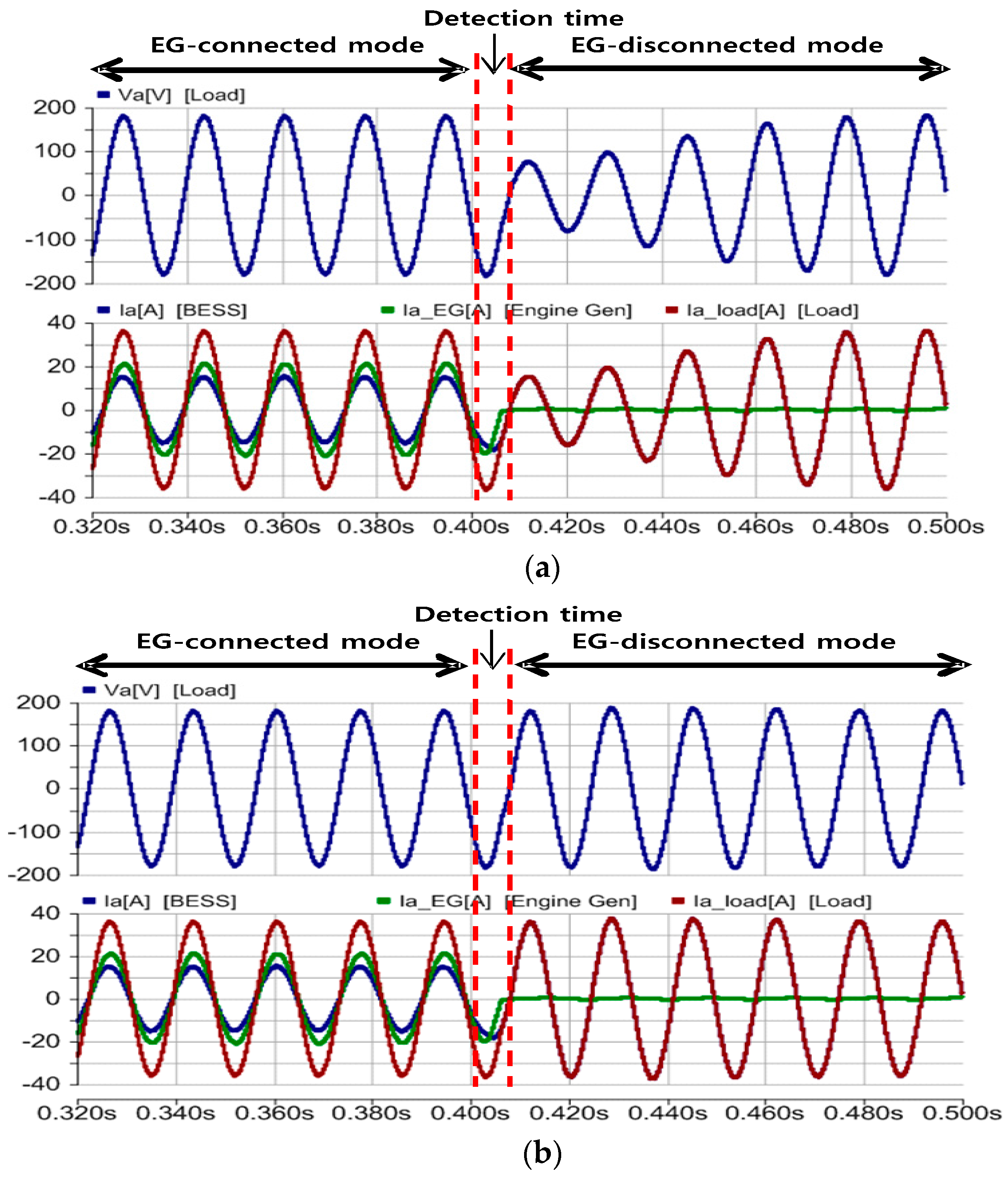
5.1. Mode Change into Separate Operation

In the mode change to separate operation, the case without initial value compensation to the voltage controller and the case with initial value compensation to the voltage controller were compared to each other. Figure 10 shows the mode change simulation results. It was assumed that the EG disconnection would occur at 0.4 s and the failure would be detected within 8 ms so that the controller would begin mode change at 0.408 s.
Figure 10a shows the simulation results without initial value compensation to the voltage controller. The BESS performs current control even after 0.4 s when the EG is disconnected until 0.408 s before the detection, and performs voltage control from 0.408 s. Immediately after the mode change into voltage control, it can be seen that the load voltage V a and load current I a _ l o a d have dropped below the values before the failure. In this case, it can be seen that approximately 60 ms is taken as transient time for the load voltage and current to be returned to the normal state by the voltage controller.
Figure 10b shows the results with initial integral value compensation to the voltage controller. The BESS performs current control until 0.408 s at which point the failure is detected and performs voltage control thereafter. Unlike Figure 10a, it can be seen that the transient time up to the normal state is approximately 4 ms. In addition, it can be seen that the load voltage and current did not change very much, except at the instant near the detection time.

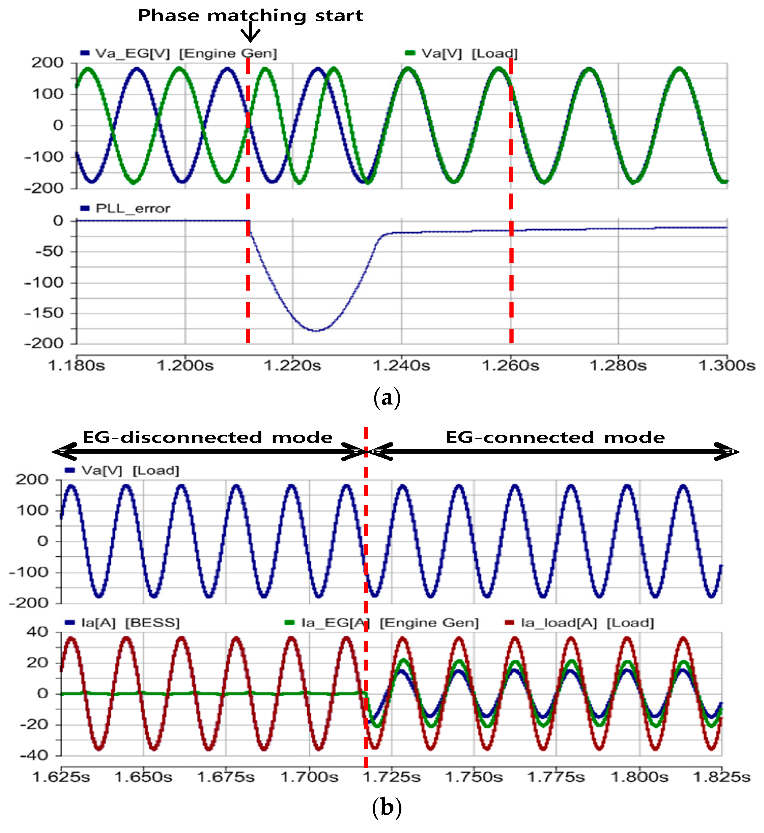
5.2. Mode Change into Reconnected Operation

Figure 11a shows the application of PLL for synchronization of the phase angle of the BESS voltage with that of the EG voltage while the BESS was supplying electric power. When the PLL synchronization begins at approximately 1.21 s, the phase angle of the load voltage V a begins to be matched with that of the EG voltage V a _ E G . If the level of the load voltage is controlled after performing phase synchronization, the EG voltage will be fixed at the DC value on the synchronous reference frame so that the voltage can be matched without any large transients.
When the phase of the load voltage and that of the EG voltage have been matched through phase synchronization and voltage level control, the STS will be closed and the mode of the BESS will be changed from voltage control to current control.
Figure 11b presents the simulation results that show the process through which the EG were reconnected to operate in parallel. After performing the synchronization described in the above, the connecting operation begins at 1.72 s. It can be seen that the EG were connected without any transient currents because the EG voltage V a b c _ E G is synchronized with the load voltage V a b c .

6. Hardware Experiment

To confirm the implementation feasibility of the proposed mode change, a hardware prototype was constructed in the laboratory based on the circuit configuration shown in Figure 1. The circuit parameters are exactly same as those shown in Table 1. The proposed mode change algorithm was programmed in C-code and loaded on a digital signal processor (DSP) control board based on TMS320F28335 which was fabricated in the laboratory. The experimental conditions were set identically to the simulation conditions and the detection time was set identical to 8 ms to compare with the simulation results. In addition, the on/off operation of STS was remotely controlled in the DSP control board.

6.1. Mode Change into Separate Operation

Figure 12 shows the experimental results where the mode was changed from a connected operation to a separate operation. Figure 12a shows the experimental results of the load voltage and current, the BESS current, and the EG current, in which the initial values were not applied. When the EG has been separated, the BESS changes the mode from current control to voltage control. The load voltage decreases during the detection time because the BESS is performing current control during that time. The load current decreases while the BESS current increases slowly. The operation mode of the BESS is changed into the voltage control approximately 8 ms later, so the load voltage slowly increases up to the nominal voltage approximately 5 cycles later. The load voltage and current reach their nominal values about 80 ms later.
Figure 12b shows the experimental results in which the initial values were applied to the voltage controller. As with the case where the initial values were not applied, the BESS performs current control until the detection and after then it performs voltage control. However, unlike Figure 12a, the load voltage rapidly increases up to the nominal voltage approximately one cycle later. The load voltage and current reach the nominal values about 16.7 ms later.

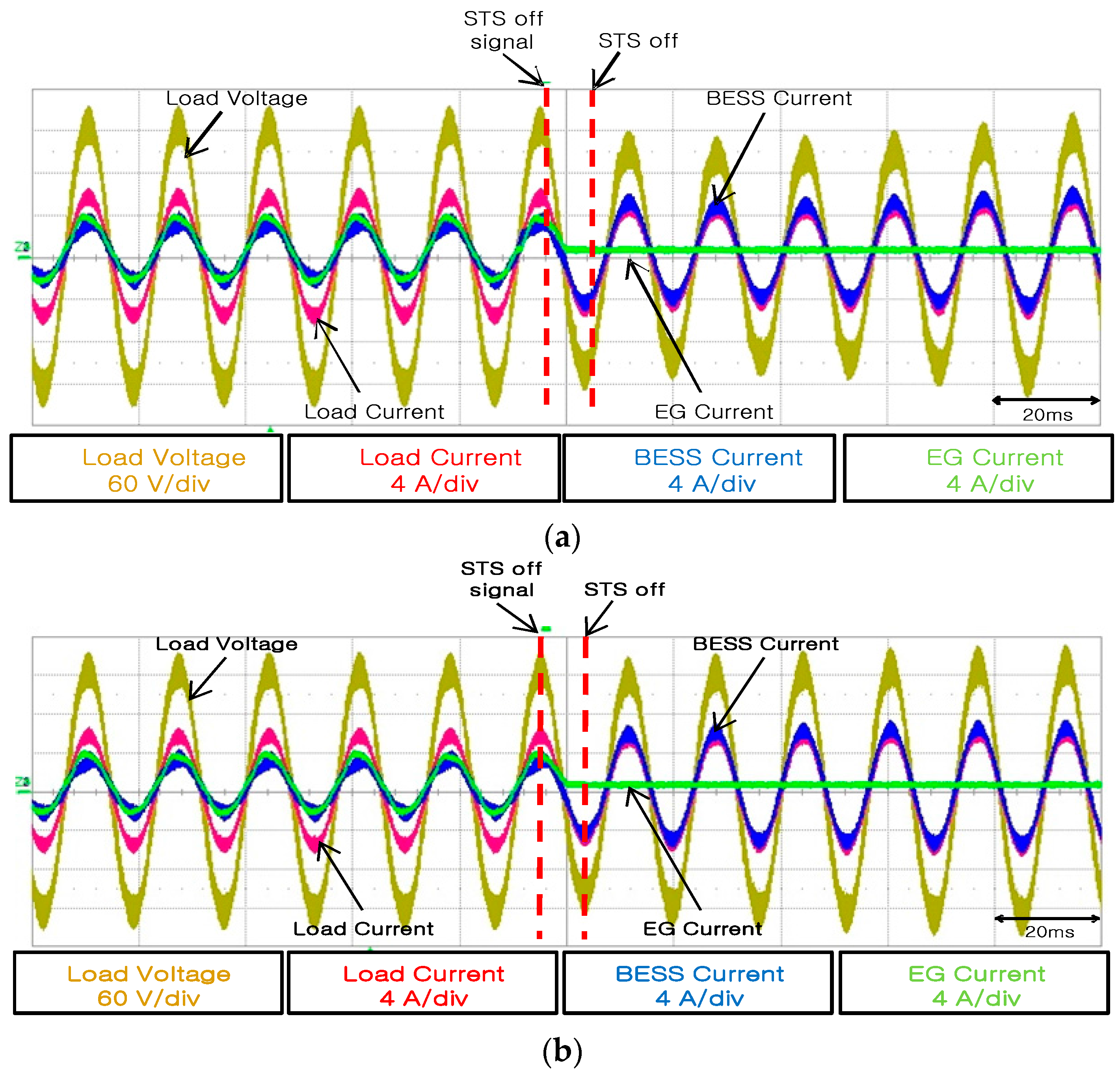
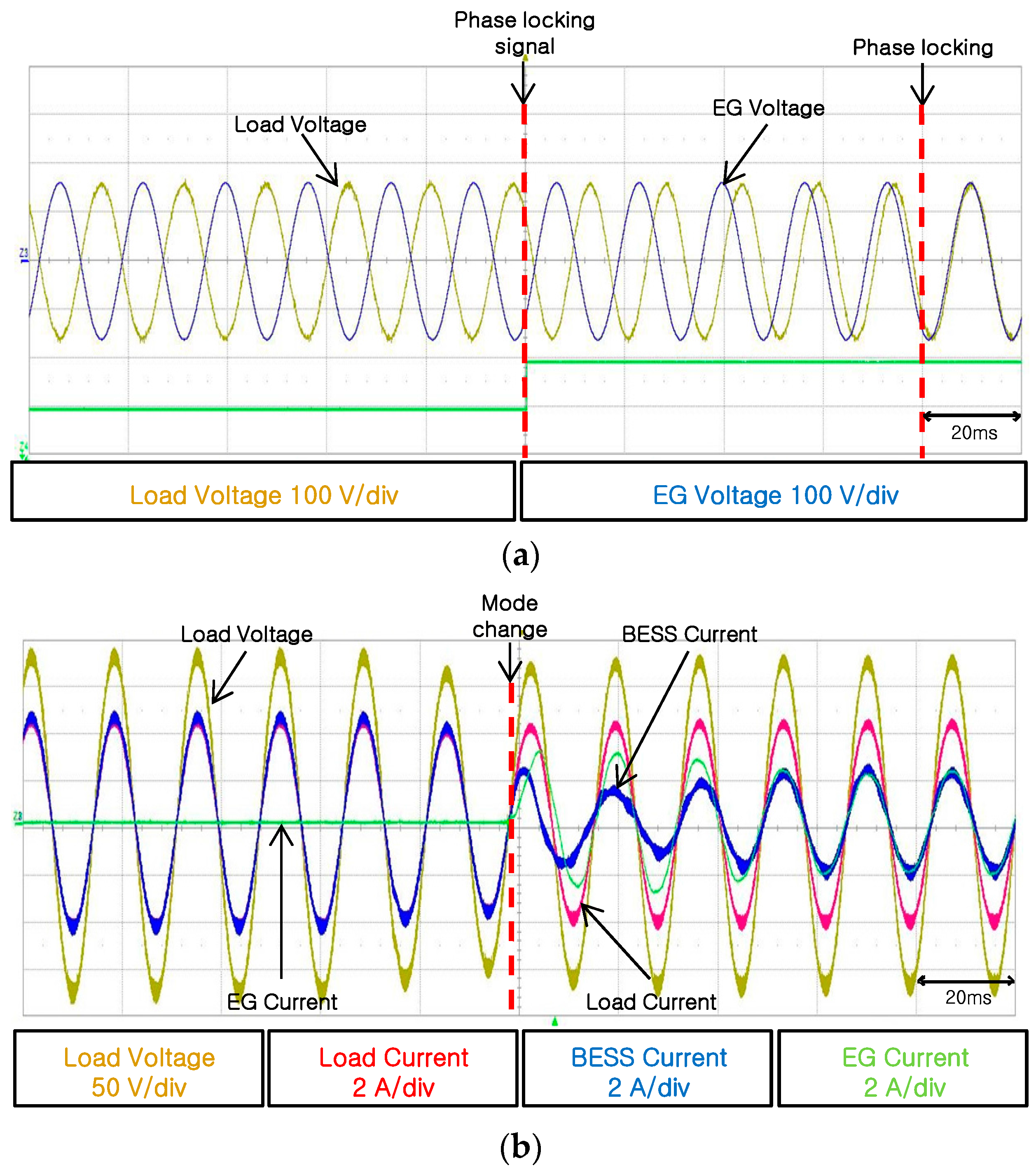
6.2. Mode Change into Connected Operation

Figure 13 shows experimental results when the mode was changed from a separate operation to a connected operation. Figure 13a shows that the load voltage is smoothly synchronized with the EG voltage through the PLL shown in Figure 9. It takes about 6 cycles in phase locking. When the phase angle of the load voltage has become the same as that of the EG voltage, the STS is closed and the operation is changed into the connected operation.
Figure 13b shows the experimental results of the load voltage and current, the EG current, and the BESS current when the mode has been changed into a connected operation after the phase synchronization. Since the load voltage accurately followed the EG voltage, the connection could be made without any transients.
When the mode was changed into a connected operation, the control mode of the BESS was changed into current control so that the EG current increased and the BESS current decreased to share the load current.

7. Conclusions

In this paper, a seamless mode change to reduce transient time during stand-alone operations was proposed. By adding appropriate initial values to the voltage controller, the proposed scheme can implement fast and stable mode changes by reducing the transient time during a mode change.
The initial values of the proposed scheme can be set as the sum of the BESS current and the EG current found out through communication or the frequency of the load voltage and can be applied in a simple manner. In addition, a method was applied to obtain information on the phase of the EG voltage when the mode is changed from a separate operation back to a connected operation and make the BESS voltage follow the phase angle of the EG voltage. The fact that mode changes were implemented smoothly without the large transients seen with the former method was identified through simulations. Through this method, the phases of two voltages can be smoothly matched so that stable connections can be made without any transient phenomena.

Acknowledgments

This work was supported by “Human Resources Development Program in Energy Technology” and “Power Generation & Electricity Delivery Core Technology Program” of the Korea Institute of Energy Technology Evaluation and Planning (KETEP), granted financial resource from the Ministry of Trade, Industry & Energy, Republic of Korea (No. 20134030200310) and (No. 20151210200080).

Author Contributions

Hyun-Jun Kim proposed the original idea and carried out the main research tasks. Yoon-Seok Lee helped to carry out computer simulations and experiments. Byung-Moon Han wrote the full manuscript and supervised the simulations and experiments. Young-Doo Yoon checked the proposed idea and the analysis results.

Conflicts of Interest

The authors declare no conflict of interest.

References

  1. Parlak, K.S.; Ozdemir, M.; Aydemir, M.T. Active and reactive power sharing and frequency restoration in a distributed power system consisting of two UPS units. Electr. Power Energy Syst. 2009, 31, 220–226. [Google Scholar] [CrossRef]
  2. Meegahapola, L.; Robinson, D.; Agalgaonkar, A.; Perera, S.; Ciufo, P. Microgrids of commercial buildings: Strategies to manage mode transfer from grid connected to islanded mode. IEEE Trans. Smart Grid 2014, 5, 1337–1347. [Google Scholar] [CrossRef]
  3. Tran, T.V.; Chun, T.W.; Lee, H.H.; Kim, H.G.; Nho, E.C. PLL-Based Seamless Transfer Control between Grid-Connected and Islanding Modes in Grid-Connected Inverters. IEEE Trans. Power Electron. 2014, 29, 5218–5228. [Google Scholar] [CrossRef]
  4. Lin, M.C.; Lu, L.Y.; Chu, C.C. Implementations of seamless transfer and active islanding detections for microgrid applications. In Proceedings of the IEEE International Symposium on Industrial Electronics (ISIE), Taipei, Taiwan, 28–31 May 2013; pp. 1–6.
  5. Balaguer, I.J.; Lei, Q.; Yang, S.; Supatti, U.; Peng, F.Z. Control for Grid-Connected and Intentional Islanding Operations of Distributed Power Generation. IEEE Trans. Ind. Electron. 2011, 58, 147–157. [Google Scholar] [CrossRef]
  6. Kim, H.; Yu, T.; Choi, S. Indirect Current Control Algorithm for Utility Interactive Inverters in Distributed Generation Systems. IEEE Trans. Power Electron. 2008, 23, 1342–1347. [Google Scholar]
  7. Yoon, S.; Kwon, J.; Park, J.; Choi, S. Indirect current control for seamless transfer of three-phase utility interactive inverters. In Proceedings of the Twenty-Sixth Annual IEEE Applied Power Electronics Conference and Exposition (APEC), Fort Worth, TX, USA, 6–11 March 2011; pp. 625–632.
  8. Yoon, S.; Oh, H.; Choi, S. Controller Design and Implementation of Indirect Current Control Based Utility-Interactive Inverter System. IEEE Trans. Power Electron. 2013, 28, 26–30. [Google Scholar] [CrossRef]
  9. Liu, Z.; Liu, J. Indirect current control based seamless transfer of three-phase inverter in distributed generation. IEEE Trans. Smart Grid 2014, 29, 3368–3383. [Google Scholar] [CrossRef]
  10. Yao, Z.; Xiao, L.; Yan, Y. Seamless Transfer of Single-Phase Grid-Interactive Inverters between Grid-Connected and Stand-Alone Modes. IEEE Trans. Power Electron. 2010, 25, 1597–1603. [Google Scholar]
  11. Tirumala, R.; Mohan, N.; Henze, C. Seamless transfer of grid-connected PWM inverters between utility-interactive and stand-alone modes. In Proceedings of the Seventeenth Annual IEEE Applied Power Electronics Conference and Exposition, Dallas, TX, USA, 10–14 March 2002; Volume 2, pp. 1081–1086.
  12. Jung, S.; Bae, Y.; Choi, S.; Kim, H. A Low Cost Utility Interactive Inverter for Residential Fuel Cell Generation. IEEE Trans. Power Electron. 2007, 22, 2293–2298. [Google Scholar] [CrossRef]
  13. Zhong, Q.C.; Hornik, T. Cascaded Current-Voltage Control to Improve the Power Quality for a Grid-Connected Inverter with a Local Load. IEEE Trans. Ind. Electron. 2013, 60, 1344–1355. [Google Scholar] [CrossRef]
  14. Mohamed, Y.A.R.I.; Radwan, A.A. Hierarchical Control System for Robust Microgrid Operation and Seamless Mode Transfer in Active Distribution Systems. IEEE Trans. Smart Grid 2011, 2, 352–362. [Google Scholar] [CrossRef]
  15. De Brabandere, K.; Bolsens, B.; van den Keybus, J.; Woyte, A.; Driesen, J.; Belmans, R. A Voltage and Frequency Droop Control Method for Parallel Inverters. IEEE Trans. Power Electron. 2007, 22, 1107–1115. [Google Scholar] [CrossRef]
  16. Lei, Q.; Yang, S.; Peng, F.Z. Multi-loop control algorithms for seamless transition of grid-connected inverter. In Proceedings of the Twenty-Fifth Annual IEEE Applied Power Electronics Conference and Exposition (APEC), Palm Springs, CA, USA, 21–25 February 2010; pp. 844–848.
  17. Hwang, T.S.; Park, S.Y. A seamless control strategy of a distributed generation inverter for the critical load safety under strict grid disturbances. IEEE Trans. Power Electron. 2013, 28, 4780–4790. [Google Scholar] [CrossRef]
  18. Ochs, D.S.; Mirafzal, B.; Sotoodeh, P. A Method of Seamless Transitions between Grid-Tied and Stand-Alone Modes of Operation for Utility-Interactive Three-Phase Inverters. IEEE Trans. Ind. Appl. 2014, 50, 1934–1941. [Google Scholar] [CrossRef]
  19. Liserre, M.; Blaabjerg, F.; Hansen, S. Design and control of an LCL-filter-based three-phase active rectifier. IEEE Trans. Ind. Appl. 2005, 41, 1281–1291. [Google Scholar] [CrossRef]
Figure 1. System configuration of a battery energy storage system (BESS) connected to a load generator.
Energies 09 00457 g001
Figure 2. Current control block diagram.
Energies 09 00457 g002
Figure 3. Voltage control block diagram.
Energies 09 00457 g003
Figure 4. Equivalent circuit of the entire system.
Energies 09 00457 g004
Figure 5. Current controller closed-loop block diagram.
Energies 09 00457 g005
Figure 6. Voltage controller closed-loop block diagram.
Energies 09 00457 g006
Figure 7. Bode diagram of closed-loop transfer function.
Energies 09 00457 g007
Figure 8. Proposed control block diagram for BESS.
Energies 09 00457 g008
Figure 9. Phase-locked loop (PLL) for EG phase angle tracking.
Energies 09 00457 g009
Figure 10. Mode change from current control to voltage control: (a) Without initial values; (b) With initial values. Fix mistakes in figure labels: EG-connected.
Energies 09 00457 g010
Figure 11. Mode change from voltage control to current control: (a) Phase angle tracking; (b) Voltage and current variations. Fix mistake in figure label: EG-connected
Energies 09 00457 g011
Figure 12. Mode change from current control to voltage control: (a) Without initial values; (b) With initial values.
Energies 09 00457 g012
Figure 13. Mode change from voltage control to current control: (a) Phase angle tracking; (b) Voltage and current variations.
Energies 09 00457 g013
Table 1. Circuit parameters for stand-alone power system.
ParameterValue
Line-to-line voltage220 V
Battery voltage450 V
Switching frequency10 kHz
Filter inductor Lf13 mH
Filter inductor Lf20.2 mH
Filter capacitor Cf5 uF
Filter damping resistor Rd1 Ω

