Article

A Study on a Linear Magnetic-Geared Interior Permanent Magnet Generator for Direct-Drive Wave Energy Conversion

1
School of Electrical Engineering, Southeast University, Nanjing 210096, China
2
College of Mechanical and Electrical Engineering, Jiaxing University, Jiaxing 314000, China
*
Author to whom correspondence should be addressed.
Energies 2016, 9(7), 487; https://doi.org/10.3390/en9070487
Submission received: 1 April 2016 / Revised: 24 May 2016 / Accepted: 17 June 2016 / Published: 24 June 2016

Abstract

:
The conventional linear permanent magnet generator (CLPMG) for direct-drive wave energy conversion (WEC) has experienced many drawbacks that are difficult to overcome such as low power density and bulky system volume. To improve power density, this paper proposes a linear magnetic-geared interior permanent magnet generator (LMGIPMG) with tubular topology, which artfully incorporates a linear magnetic gear into a linear permanent magnet generator. The operating principle of the LMGIPMG is introduced, and a detailed analysis of air gap flux density, thrust force characteristics, and no-load and load performances are presented and discussed by using finite element method. The CLPMG, which produces the same power as the LMGIPMG, has about four times the volume of the latter. A prototype CLPMG is manufactured to verify simulation results against experimental tests. The design method and the operation conditions of LMGIPMG and CLPMG are both consistent; thus, the performance of LMGIPMG meets the operation requirements of the direct-drive WEC.

1. Introduction

At present, solutions to the energy crisis need to be explored through alternative, renewable, and clean energy sources. An extremely abundant and promising source of energy exists in oceans. Among these forms of ocean energy, significant opportunities and benefits have been identified in the area of ocean wave energy extraction [1,2]. Since the 1970s, researchers from all over the world have studied wave energy conversion (WEC) systems that can harness the motion of ocean waves and convert it into electrical energy [3].
Historically, WEC systems use a conventional rotary generator that requires hydraulic or pneumatic equipment. Linear generators, such as linear switched reluctance generators or linear permanent magnet generators, have been used in several full-scale technologies because their mechanical simplicity makes them more reliable than other generators [4,5]. Linear generators are compatible with low-speed waves, namely, the direct-drive WEC, which directly transmits the wave energy into electrical energy without complex gearing systems and improves the efficiency of the entire system [6].
Wave energy is concentrated at low frequencies and at low, alternating velocities, thereby causing difficulty in efficient conversion and transmission to a grid and limiting the options for efficient power takeoff technology. In particular, a conventional linear permanent magnet (PM) generator reciprocates at such low-speed wave motions and requires a large amount of iron, which makes the generator considerably heavy. When operating in high-speed mode, linear generators would have high power density and low cost. Potentially, magnetic gear technology becomes a good candidate for accelerating the speed of linear PM generators.
The concept of a magnetic gear using PMs was first proposed in 1987 [7]. The magnetic gear shows several distinct advantages, such as minimum acoustic noise, maintenance-free performance, inherent overload capability, and improved reliability [8,9]. This device is becoming increasingly attractive for various applications such as renewable power generation. Magnetic-geared PM machines have been investigated by researchers in recent years. Jian presents a magnetic-geared outer-rotor permanent-magnet brushless machine, integrating a high-speed PM brushless generator with a coaxial magnetic gear for wind power generation [10]. Atallah proposes a “pseudo” direct-drive machine by combining a magnetic gear and electrical machine with high torque density and power factor [11]. The machine proposed by Li consists of a linear magnetic gear cascaded with a linear PM generator for oceanic wave energy harvesting [12]. However, its elongated structure is complex and difficult to process. A double-stator single-rotor magnetic-geared machine that achieves low-speed high-torque merit is presented by Liu [13]. Niu proposes a tubular linear magnetic-geared machine that aims to improve thrust force density and enhance efficiency [14]. Although the magnetic-geared generator has high transmission force between the translators, the force generated by the windings is low because the PMs are placed at the tip of the teeth of the stator and hinder the magnetic flux generated by the windings. Therefore, we propose a magnetic-geared generator that adopts a simple structure and fewer PMs; the PMs are placed in the stator slots and half of the PMs are saved. This proposed model is called linear magnetic-geared interior PM generator (LMGIPMG).
We present the LMGIPMG, which artfully integrates a linear high-speed PM generator with a linear magnetic gear mechanically and magnetically. The purpose of this proposal is to achieve high power density, high efficiency, and reduced costs in WEC. The slow reciprocating wave motion is directly harnessed by the low-speed translator of the proposed generator. Then, the high-speed translator is accelerated by the gearing effect to actuate the generator, thereby producing higher output voltage. The study compares the linear magnetic-geared interior PM generator with the conventional linear PM generator (CLPMG). We analyze and compare the performance of the two generators by finite element analysis (FEA) and experimental tests. The results confirm that the LMGIPMG with a smaller volume can offer higher power density than the CLPMG. Therefore, a direct-drive WEC system mainly composed of LMGIPMG is feasible and effective and can be used to supply electric power for oceanographic observation instruments in isolated islands.

2. System Configuration and Operation Principle

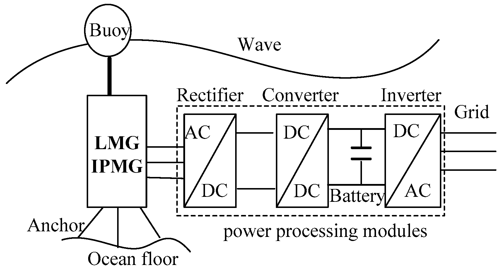
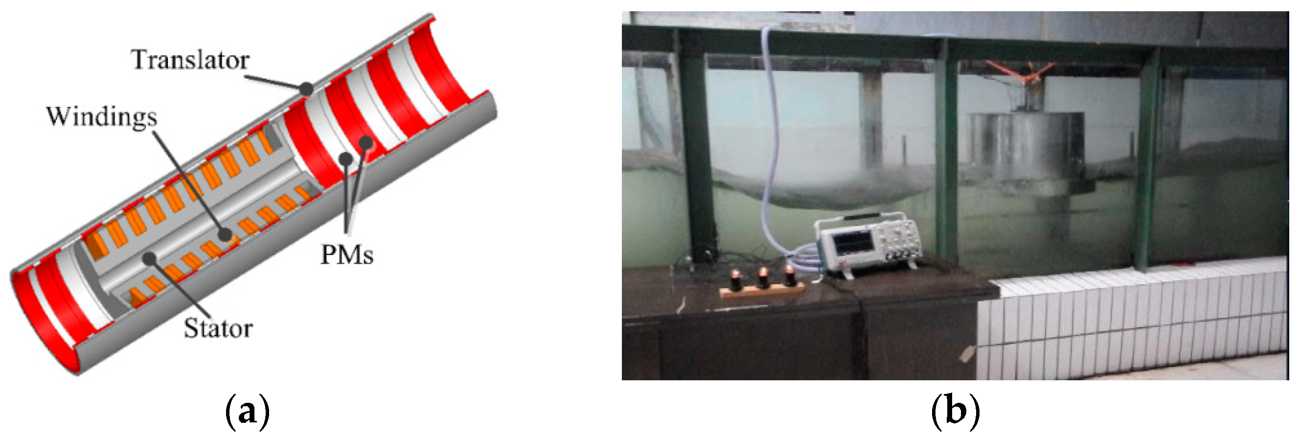
2.1. System Description

Figure 1 shows the direct-drive WEC system that consists of the LMGIPMG, buoy, mooring system, and power processing modules. A buoyant float, when excited by the heave motion of the waves, moves relative to a spar anchored to the ocean floor. The LMGIPMG, which combines a linear magnetic gear and a linear high-speed PM generator, achieves good power density and low cost. The output voltages are irregular because of the alternating speed of waves. Therefore, power modules are applied to conduct the electricity to the grid.

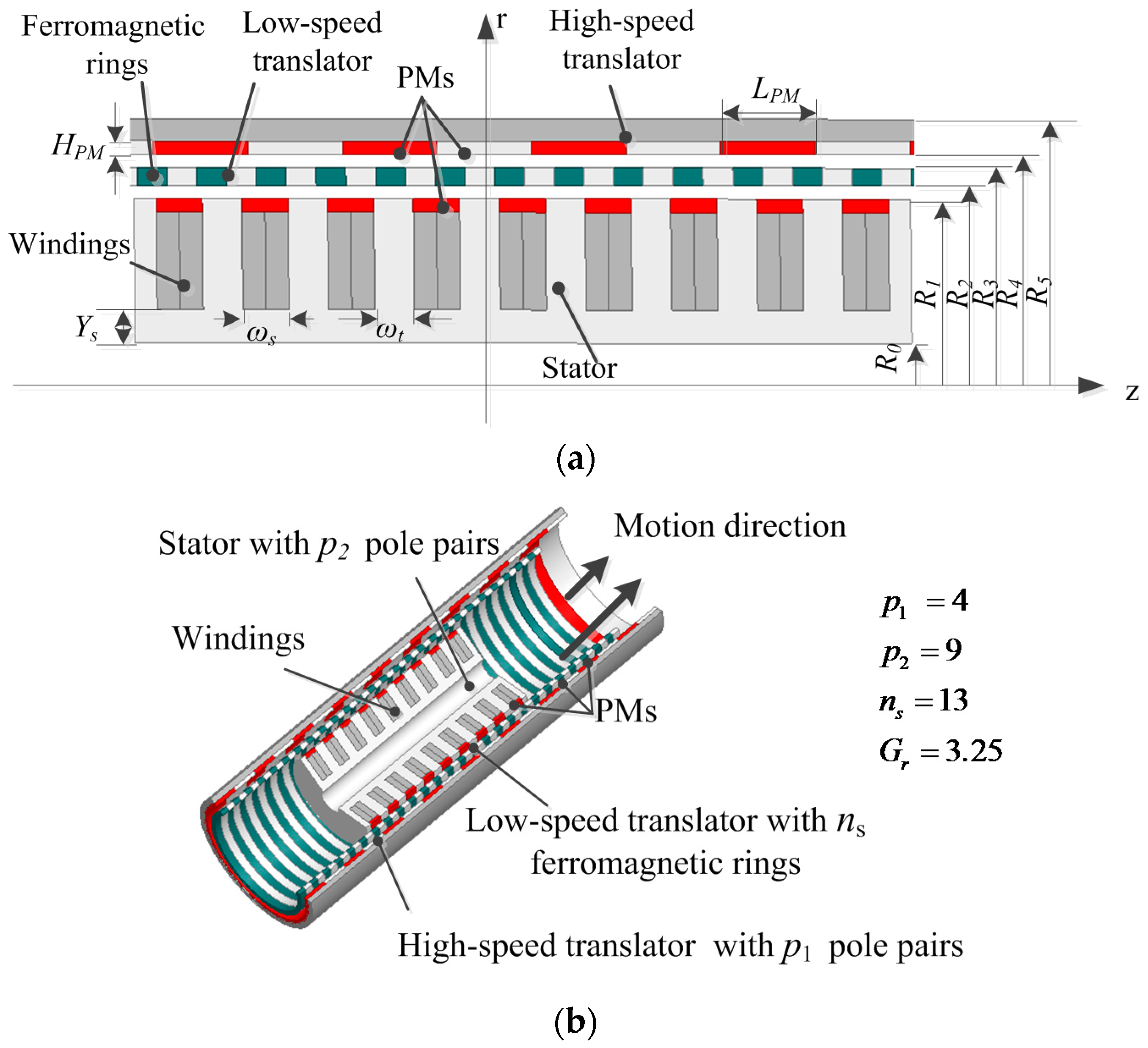
2.2. Operational Principle of LMGIPMG

Figure 2 shows that the LMGIPMG comprises the stator and the high-speed translator carrying PM arrays with different numbers of poles and an intermediate low-speed translator that possesses a set of annular ferromagnetic rings. The force and speed transformation between the two translators can be transmitted by the modulation effect of magnetic field of the ferromagnetic rings to generate an appropriate space harmonic with the same pole pairs as the other PM armature [8,9]. The corresponding relationships should be satisfied.
p 1 + p 2 = n s
where p1 is the number of PM pole pairs in the high-speed translator, p2 is the number of PM pole pairs in the stator, and ns is the number of ferromagnetic rings in the low-speed translator.
The number of pole pairs in the space harmonic flux density distribution produced by either PM armature is given by:
p m , k = | m p + k n s |
where m = 1 , 3 , 5 , , , k = 0, ± 1 ,   ± 2 , ,   ± , and p is the PM pole-pair number of the high-speed translator or the stator.
The linear velocity of the space harmonics of the air gap magnetic field is given by:
v m , k = m p m p + k n s v r + k n s m p + k n s v s
where   v s , v r   are the linear velocities of the ferromagnetic rings and the PM armature under consideration, respectively. When   m = 1 ,   k = 1 , and the largest space harmonic component is obtained.
The gear ratio of the high- and low-speed translator is governed by:
G r = n s / p 1
The basic operational principle of the LMGIPMG is described as follows: the low-speed translator connected to the buoy moves up and down with a slow reciprocating wave motion. The high-speed translator accelerated by the gearing effect simultaneously operates at a high speed to actuate the generator. The windings of the generator cut the high-speed magnetic field expedited by the predetermined gear ratio and produce a higher output voltage than the conventional low-speed PM generator at the same operation conditions. The proposed generator can match the low-speed wave motion and adopt high-speed design; thus, it is an economical and technological choice for direct-drive WEC.

2.3. Machine Design and Parameters

The LMGIPMG structure includes the high-speed translator with PMs of four pole pairs, the stator with nine pieces of PMs inserted in the slots, as well as the low-speed translator composed of ferromagnetic segments and polyester segments. The ferromagnetic segments can be made of laminated irons, which are adhered later together by polyester material to provide mechanical strength for force transmission. In addition, the gear ratio of the high-speed translator to the low-speed translator is set at 3.25.
In the design, the high-speed translator is shared by the magnetic gear and the linear PM generator, and PMs on the stator are inserted in the slots; thus, a small volume of the proposed generator can be achieved by electromagnetic and mechanical coupling. To investigate the electromagnetic characteristics and the unique advantages of the proposed generator, the CLPMG was compared with the LMGIPMG. The key parameters of the LMGIPMG and CLPMG are listed in Table 1.

3. Performance Analysis

The analysis of magnetic flux density in the air gaps, thrust force, and no-load and load operations are calculated with the FEM to assess the performance of the proposed machine.

3.1. Magnetic Field Distribution

The magnetic field distribution under no-load operation is depicted in Figure 3. The air gap flux densities of the machine are analyzed when PMs on the high-speed translator and the stator both serve as field excitations. Figure 4 shows the radial flux densities in the air gaps adjacent to the stator and the high-speed translator, respectively, and the corresponding space harmonic spectra. The 4th and 9th space harmonic components are the most dominant ones. The ferromagnetic rings modulate the appropriate harmonic components that possess the same number of pole pairs as the PMs of the other armature.

3.2. Force Characteristics

Figure 5a depicts the variation of the static thrust force with time when the low-speed translator travels incrementally and the high-speed translator remains stationary. The maximum thrust forces developed by the low-speed and high-speed translators are 633 N and 196 N, respectively. The steady force waveforms when the low-speed and high-speed translators travel at 0.4 m/s and 1.3 m/s, respectively, are shown in Figure 5b. The ratio of force on the low-speed translator to the force on the high-speed translator is about 3.23, which is close to the gear ratio and is consistent with the fundamental principle of magnetic gears.

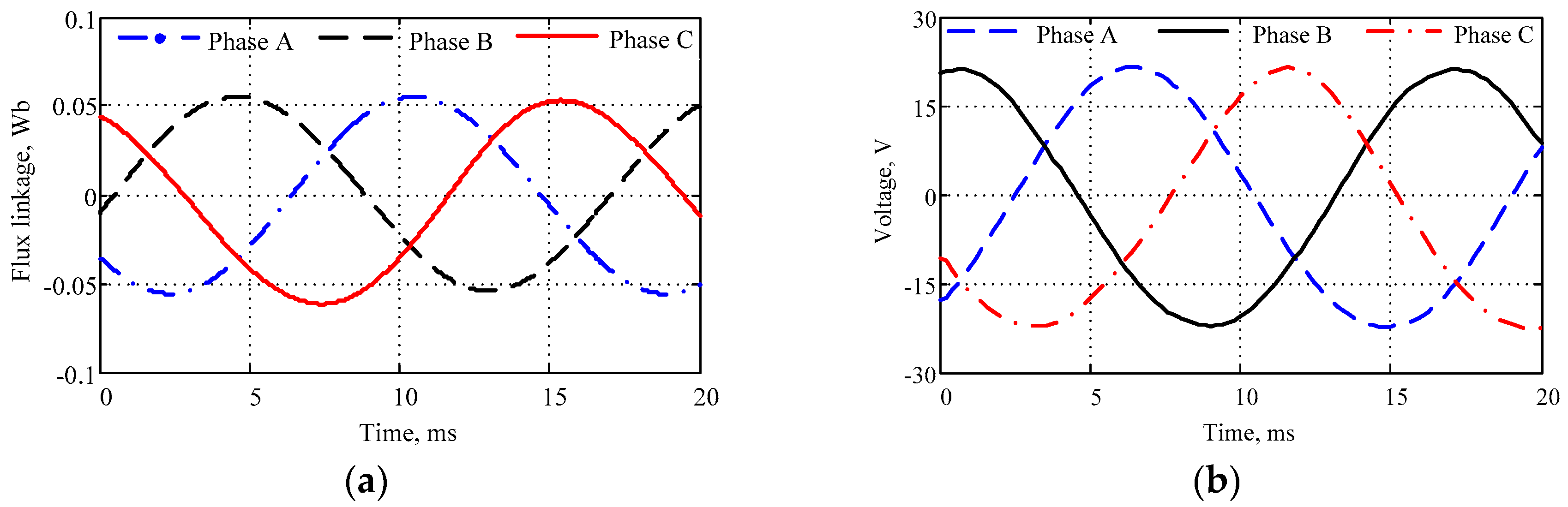
3.3. Performance Analysis at a Constant Speed

For a direct-drive WEC system, the speed will not be a constant value. To facilitate the analysis, the velocity of the low-speed translator of the LMGIPMG is assumed to be a constant value, i.e., 0.4 m/s. According to the gear ratio, the corresponding velocity of the high-speed translator is 1.3 m/s. The no-load performance of the LMGIPMG is investigated by using FEA. As shown in Figure 6, the flux linkage and no-load electromotive force (EMF) of the LMGIPMG vary sinusoidally with time. The no-load EMF can achieve a peak value of 21.7 V at a constant speed of 0.4 m/s for the low-speed translator and 1.3 m/s for the high-speed translator. The symmetrical flux linkage and phase voltage waveforms show that the design of three-phase windings is reasonable.
Three-phase symmetrical resistance loads and resistance-inductance loads are implemented to investigate the load performance of the LMGIPMG. Figure 7a shows that when the load resistance is 6 Ω, the peak valve of the voltage is 17.1 V and the peak current reaches 2.86 A at the constant speed of 0.4 m/s. The symmetrical three-phase voltages and currents for R = 20 Ω and L = 50 mH are shown in Figure 7b. A peak voltage of 19.1 V and a peak current of 0.69 A can be obtained, and a phase offset of 43.5 degrees appears between the voltage and the current.

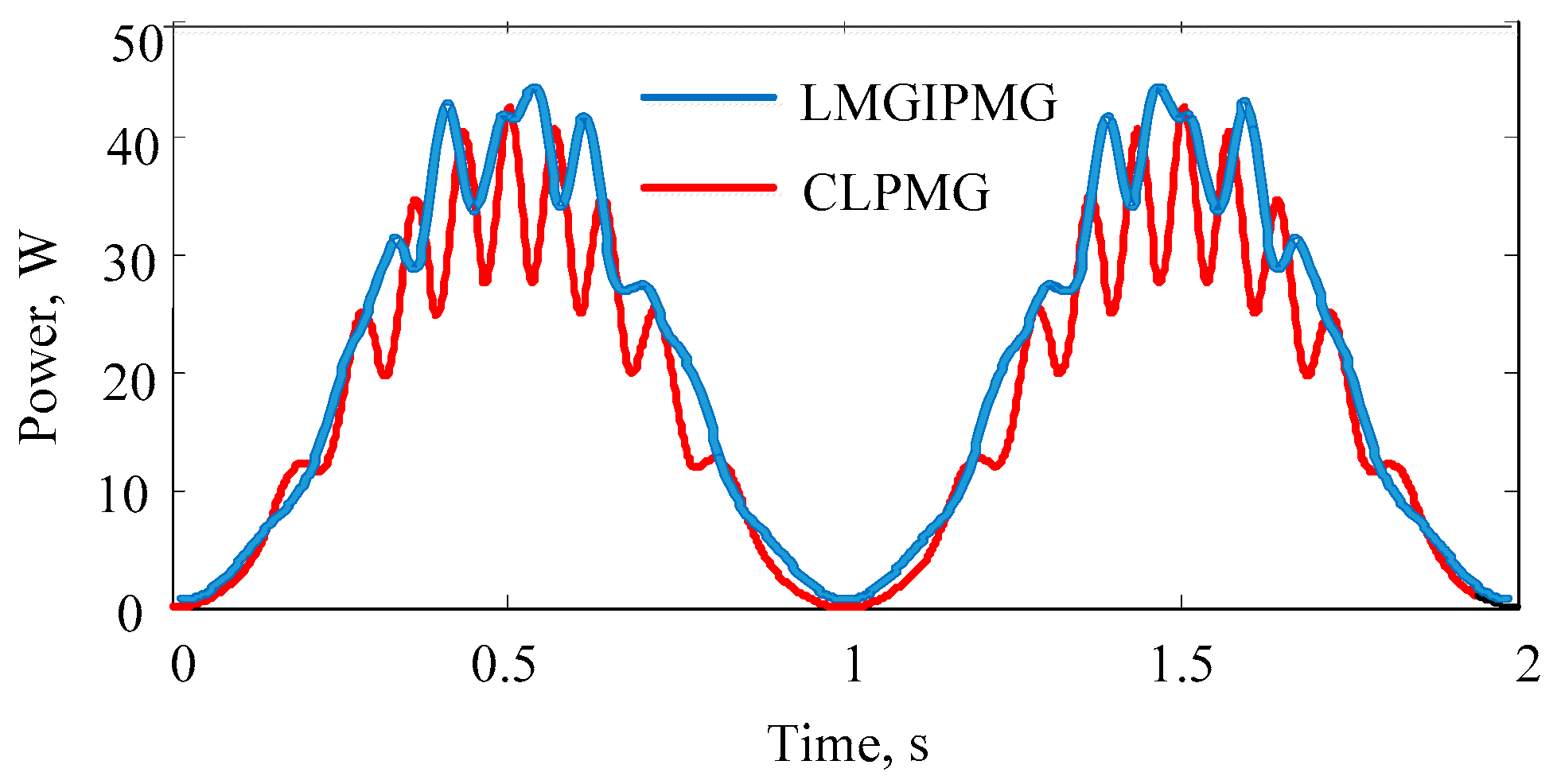
3.4. Performance Analysis at a Sinusoidal Speed

In a real WEC system, the motion of the device is highly complicated. In this study, the WEC is considered as a sphere that is semi-submerged in its equilibrium position. When an incident wave arrives, the sphere moves in the heave direction and a relative movement between the sphere and the wave surface begins.
An incident wave of height H = 2A, period T, and phase angle α produces a heave displacement of the free water surface equal to
x ( t ) = A cos ( 2 π T t + α ) .
For the sake of analysis, the translator speed of the generator in an ideal situation (ignoring inertia, friction, wave reflection and other effects) can be expressed as follows:
v ( t ) = π H T sin ( 2 π T t + α )
The wave motion of H = 0.2 m and T = 2 s is used in the experiment because the width and the depth of wave flume are limited. The sinusoidal speed v(t) = 0.314sin(3.14t) is exerted on the low-speed translator, while the high-speed translator is expedited by magnetic gear. The waveform of no-load EMF in a complete cycle at a sinusoidal speed is shown in Figure 8a. Simultaneously, the variations of the speed and position of the low-speed translator are illustrated in Figure 8b.
When the speed increases gradually from zero to the maximum, the low-speed translator varies from the lowest level to the equilibrium position, at which the no-load EMF reaches the maximum value. As the speed decreases, the low-speed translator continues to move up, but the no-load EMF amplitudes decreases gradually. At t = 1 s, the speed is zero, the low-speed translator reaches the highest level, and the no-load EMF decreases to zero. At the second half cycle of speed, the position of the low-speed translator and the no-load EMF amplitudes are similar to those of the first half cycle.

4. Comparison Results

This paper presents a comparison of LMGIPMG and CLPMG based on the same output power and operation conditions to illustrate further the characteristics of the LMGIPMG. The method of designing the LMGIPMG and CLPMG are both consistent. The performance of the two generators are analyzed and compared quantitatively by FEA and experimental tests.
In the CLPMG design, the output power of a full-scale device is 5 kW with a translator speed of 0.4 m/s. A prototype of 1:100 is manufactured to save costs and to verify the design method. For the CLPMG, the power density of the external translator structure is about seven to eight times that of the internal translator structure at the same volume. Therefore, the external translator structure of the CLPMG is used. Additionally, Halbach array and auxiliary slots are used to optimize the performance of the CLPMG. The CLPMG structure and a photograph of the WEC system in the wave tank are shown in Figure 9.

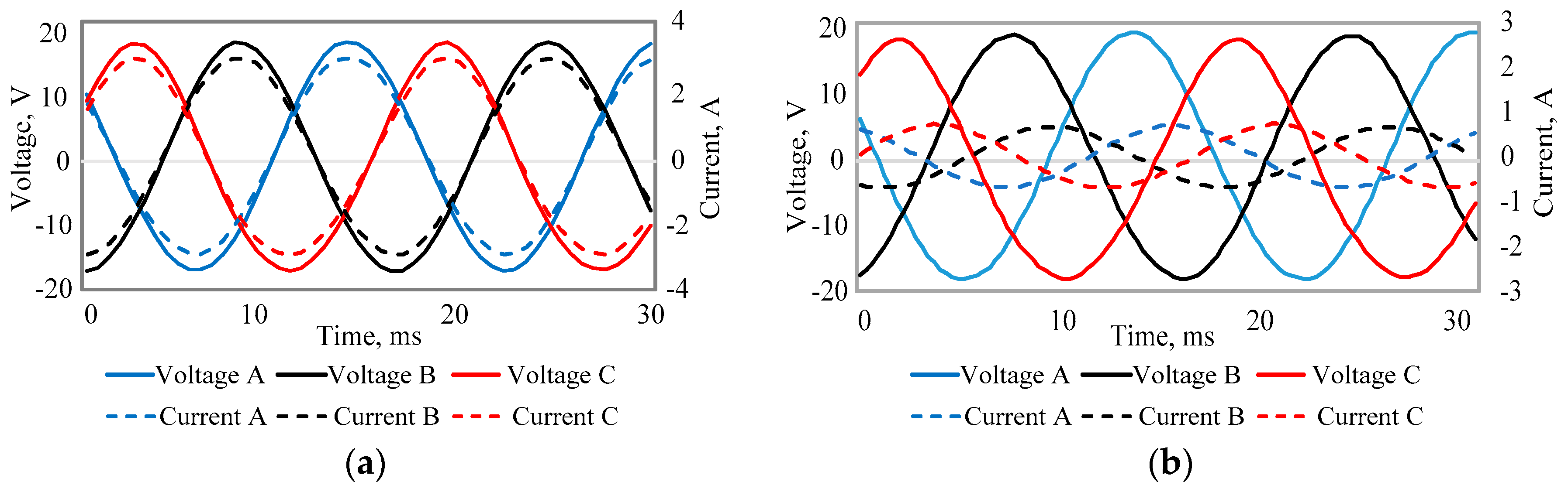
4.1. Three-Phase EMF

Figure 10 depicts the no-load EMF of the two generators under the same operation conditions (translator speed, electromagnetic force, mesh subdivision, step size, etc.), and a constant speed of 0.4 m/s. The peak values of no-load EMF of the LMGIPMG and CLPMG are 21.7 V and 22.5 V. According to the formula f = v/2τ, the frequency of the three-phase induced EMF is determined by the PM pole pitch and the translator speed. Given a pole pitch of 10.75 mm and a constant speed of 0.4 m/s, the frequency of the LMGIPMG is 60.5 Hz. Likewise, the frequency of the CLPMG is 9.3 Hz. Additionally, the same conclusions on the dominant frequency can be obtained through a fast Fourier transform (FFT) of the no-load EMF time series. Based on the design parameters of the LMGIPMG and CLPMG in Table 1, the no-load EMF frequency of the LMGIPMG is approximately 6.5 times that of the CLPMG.
Load performance comparisons of two generators at a constant speed are conducted to verify the validity of the proposed LMGIPMG. Simulation analyses from FEA and experimental tests are conducted to analyze the performance of the CLPMG based on the assumption that the CLPMG works at a constant speed of 0.4 m/s. Three-phase star-connected resistance loads are connected in a series with the three-phase windings. Simulation results (black lines) and experimental waveforms (colored lines) of the CLPMG for R = 10 Ω at a constant speed of 0.4 m/s are presented in Figure 11a. The shape of the experimental waveform corresponds with that of the calculation results from FEA. The simulation peak voltage of the CLPMG is 19.6 V, whereas the experiment peak voltage is only 15 V. Regardless of the eddy current losses, stray losses, and friction for FEA, the experimental results are slightly smaller than that of FEA.
As shown in Figure 11b, when the resistance load is 10 Ω, the symmetrical three-phase voltage of the LMGIPMG is obtained by FEA. The peak voltage of the LMGIPMG is 19.3 V at a constant speed of 0.4 m/s. The three-phase voltages are very close to sinusoid and are also symmetric with each other when the LMGIPMG and CLPMG are both at constant speed. Based on the same output voltage, operation conditions, and design methodology, the volume of the LMGIPMG can be decreased significantly by adopting the concept of magnetic gears.
Furthermore, a quantitative comparison is made on the three-phase EMF of the LMGIPMG and CLPMG for resistance load at the sinusoidal speed of v(t) = 0.314sin(3.14t). The simulation results (black lines) and experimental waveforms (colored lines) of the CLPMG for R = 10 Ω at the sinusoidal speed are depicted in Figure 12a. The peak EMF from FEA of the CLPMG is approximately 13.8 V, whereas the peak test value reaches 12 V. Given the wave flume width of 1 m and the buoy diameter of 0.5 m, the wave is affected by the float reflection wave and the translator speed is reduced. Therefore, the experimental values are smaller than the simulation results.
A time-varying sinusoidal speed is also exerted on the low-speed translator to assess the performance of the LMGIPMG. Figure 12b shows the simulation waveform of the three-phase EMF of the LMGIPMG for R = 10 Ω at the sinusoidal speed. The peak EMF of LMGIPMG reaches 15.3 V at t = 0.5 s and t = 1.5 s; the speed reaches the maximum value when the translator is in equilibrium position. Under the same operation conditions, the performance of the LMGIPMG with a much smaller volume is similar to that of the CLPMG, whether operating in no-load or full-load condition and whether they work at constant or sinusoidal speed. Despite its small size, the LMGIPMG can offer high-quality output voltage, and its efficient performance meets the requirements of WEC.

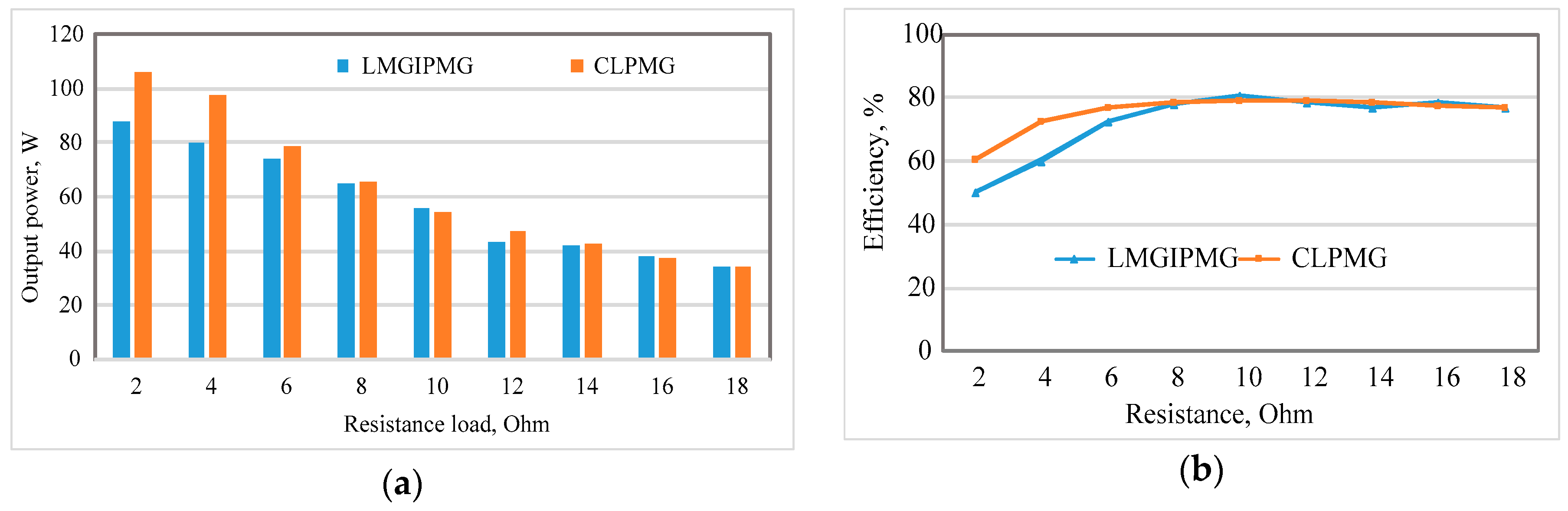
4.2. Output Power and Efficiency

The comparison of output power and efficiency of the LMGIPMG and CLPMG at a constant speed of 0.4 m/s is shown in Figure 13. With the increment of load resistance, the output power of two generators decreases gradually, as shown in Figure 13a. For the rated resistance load R = 10 Ω, the output power of the LMGIPMG and CLPMG are 56 W and 54.7 W, respectively. The efficiency of the generator is an important parameter. Figure 13b shows that the efficiency increases with increasing resistance load and then decreases slightly. The maximum efficiencies of the LMGIPMG and CLPMG reach 80.1% and 79.1%, respectively, at a load of 10 Ω.
Figure 14 shows the instantaneous power of the LMGIPMG and CLPMG at 10 Ω at the sinusoidal speed of v(t) = 0.314sin(3.14t). The instantaneous power is unstable, and the electricity can be supplied to consumers only through the use of power processing modules. The instantaneous power of the LMGIPMG and CLPMG are respectively approximate, and they possess the same varying trend. When the low-speed translator reaches the maximum speed, the peak power of the LMGIPMG reaches 45 W and the average power is 23 W. For the LMGIPMG with smaller volume, the power density is about four times that of the CLPMG.

4.3. Voltage Regulation

Voltage regulation is a measure that states the difference between no-load EMF and output voltage as a percentage of the rated voltage. Voltage regulation is determined by the inherent characteristics of the generator and has a significant effect on the normal operation of the electrical equipment. Voltage regulation is expressed as follows:
U = E O U U N × 100 ,
where EO is the no-load EMF, U is the output voltage, and UN is the rated voltage. The reduction of voltage regulation is highly important in the design of a PM generator given the difficulty of adjusting the air-gap magnetic field. Figure 15 shows that the voltage regulations of the two generators both decrease with increasing resistance. The voltage regulation of the LMGIPMG is smaller than that of the CLPMG. In particular, for R = 20 Ω and a speed of 0.4 m/s, the voltage regulations of the LMGIPMG and CLPMG are 4.3% and 11.6%, respectively. The calculated results of the two models show that the LMGIPMG is more stable than the CLPMG.

5. Conclusions

The LMGIPMG with a simple structure and fewer PMs was proposed for the direct-drive WEC. The proposed generator, which artfully integrates a linear magnetic gear with a linear PM brushless machine, can harness the slow reciprocating wave motion directly and allow high-speed generator operation. To investigate the electromagnetic characteristics and the unique advantages of the proposed generator, the LMGIPMG was compared with a CLPMG with the same output power under the same operating conditions. The CLPMG had approximately 4.13 times active volume and four times active mass as the LMGIPMG. The LMGIPMG can offer higher power density and is cheaper than the CLPMG. FEA was implemented to calculate the magnetic fields of the two generators and obtain the no-load and load performance. Performance analysis based on FEA and experiments verify that the proposed generator is feasible for the WEC.

Acknowledgments

This work was supported by the Natural Science Foundation of China (No.41576096), the Fundamental Research Funds for the Central Universities, and the Research and Innovation Funds for Graduate Students in Jiangsu Province (No. KYLX15_0130).

Author Contributions

All the authors have contributed their efforts to make sure the paper is qualified. Haitao Yu and Minqiang Hu designed and supervised the work. Ningjun Feng and Chunyuan Liu conducted the simulation and experiment parts. Lei Huang and Zhenchuan Shi discussed the experiment results.

Conflicts of Interest

The authors declare no conflict of interest.

References

  1. Brekken, T.K.A.; von Jouanne, A.; Han, H.Y. Ocean wave energy overview and research at Oregon State University. In Proceedings of Power Electronics and Machines in Wind Applications, Lincoln, NE, USA, 24–26 June 2009; IEEE: New York, NY, USA.
  2. Scruggs, J.; Jacob, P. Harvesting Ocean Wave Energy. Science 2009, 323, 1176–1178. [Google Scholar] [CrossRef] [PubMed]
  3. Muetze, A.; Vining, J.G. Ocean wave energy conversion—A survey. Proc. IEEE Ind. Appl. Conf. 2006, 3, 1410–1417. [Google Scholar]
  4. Mueller, M.A. Electrical generators for direct drive wave energy converters. IEE P-GENER TRANSM D 2002, 149, 446–456. [Google Scholar] [CrossRef]
  5. Chen, Z.X.; Yu, H.T.; Hu, M.Q. The research on direct-drive wave energy conversion system and performance optimization. Acta Oceanol. Sin. 2014, 33, 178–183. [Google Scholar] [CrossRef]
  6. Liu, C.Y.; Yu, H.T.; Hu, M.Q.; Liu, Q.; Zhou, S.G.; Huang, L. Research on a permanent magnet tubular linear generator for direct drive wave energy conversion. IET Renew. Power Gener. 2014, 8, 281–288. [Google Scholar] [CrossRef]
  7. Tsurumoto, K.; Kikushi, S. A new magnetic gear using permanent magnet. IEEE Trans. Magn. 1987, 23, 3622–3624. [Google Scholar] [CrossRef]
  8. Atallah, K.; Howe, D. A novel high-performance magnetic gear. IEEE Trans. Magn. 2001, 37, 2844–2846. [Google Scholar] [CrossRef]
  9. Holehouse, R.C.; Atallah, K.; Wang, J. Design and Realization of a linear magnetic gear. IEEE Trans. Magn. 2011, 47, 4171–4174. [Google Scholar] [CrossRef]
  10. Jian, L.; Chau, K.T.; Jiang, J.Z. A magnetic-geared outer-rotor permanent-magnet brushless machine for wind power generation. IEEE Trans. Ind. Appl. 2009, 45, 954–962. [Google Scholar] [CrossRef]
  11. Atallah, K.; Rens, J.; Mezani, S.; Howe, D. A novel ‘pseudo’ direct-drive brushless permanent magnet machine. IEEE Trans. Magn. 2008, 44, 4349–4352. [Google Scholar] [CrossRef]
  12. Li, W.; Chau, K.T.; Jiang, J.Z. Application of linear magnetic gears for pseudo-direct-drive oceanic wave energy harvesting. IEEE Trans. Magn. 2011, 47, 2624–2627. [Google Scholar] [CrossRef] [Green Version]
  13. Liu, C.; Chau, K.T.; Zhang, Z. Novel Design of Double-Stator Single-Rotor Magnetic-Geared Machines. IEEE Trans. Magn. 2012, 48, 4180–4183. [Google Scholar] [CrossRef] [Green Version]
  14. Niu, S.; Ho, S.L.; Fu, W.N. Performance analysis of a novel magnetic-geared tubular linear permanent magnet machine. IEEE Trans. Magn. 2011, 47, 3598–3601. [Google Scholar] [CrossRef]
Figure 1. Wave energy conversion (WEC) system.
Energies 09 00487 g001
Figure 2. Proposed linear magnetic-geared interior permanent magnet generator (LMGIPMG) for WEC system: (a) 2D schematic; (b) 3D schematic.
Energies 09 00487 g002
Figure 3. Magnetic field distribution of LMGIPMG at no load.
Energies 09 00487 g003
Figure 4. Radial flux density and harmonics in air gaps: (a) flux density in air gap adjacent to stator; (b) space harmonic spectrum in air gap adjacent to stator; (c) flux density in air gap adjacent to high-speed translator; (d) space harmonic spectrum in air gap adjacent to high-speed translator.
Energies 09 00487 g004
Figure 5. Force characteristics on high- and low-speed translators: (a) static force; (b) steady force.
Energies 09 00487 g005
Figure 6. Flux linkage and no-load electromotive force (EMF) of LMGIPMG at constant speed of 0.4 m/s: (a) flux linkage; (b) no-load EMF.
Energies 09 00487 g006
Figure 7. Waveforms of voltage and current for resistance load and resistance-inductance load at constant speed of 0.4 m/s: (a) R = 6 Ω; (b) R = 20 Ω and L = 50 mH.
Energies 09 00487 g007
Figure 8. Performance analysis at sinusoidal speed of v(t) = 0.314sin(3.14t): (a) three-phase no-load EMF; (b) variations of speed and position of low-speed translator.
Energies 09 00487 g008
Figure 9. Conventional linear permanent magnet generator (CLPMG) for WEC system: (a) structure of CLPMG; (b) WEC system in wave tank.
Energies 09 00487 g009
Figure 10. Comparison of no-load EMF of two generators at constant speed of 0.4 m/s.
Energies 09 00487 g010
Figure 11. Three-phase EMF comparison of two generators for R = 10 Ω at constant speed of 0.4 m/s: (a) simulation results (black lines) and experimental waveforms (colored lines) of CLPMG; (b) simulation waveforms of LMGIPMG.
Energies 09 00487 g011
Figure 12. Three-phase EMF comparison of two generators for 10 Ω at sinusoidal speed of v(t) = 0.314sin(3.14t): (a) simulation results (black lines) and experimental waveforms (colored lines) of three-phase EMF of CLPMG; (b) simulation waveform of three-phase EMF of LMGIPMG.
Energies 09 00487 g012
Figure 13. Comparison of output power and efficiency of LMGIPMG and CLPMG at constant speed of 0.4 m/s: (a) comparison of output power; (b) comparison of efficiency.
Energies 09 00487 g013
Figure 14. Instantaneous power of LMGIPMG and CLPMG for 10 Ω at sinusoidal speed of v(t) = 0.314sin(3.14t).
Energies 09 00487 g014
Figure 15. Comparison of voltage regulation.
Energies 09 00487 g015
Table 1. Basic Parameters of linear magnetic-geared interior permanent magnet generator (LMGIPMG) and conventional linear permanent magnet generator (CLPMG).
LMGIPMGCLPMG
R0Inner radius of stator (mm)10R0Inner radius of stator (mm)10
R1Outer radius of stator (mm)28R1Outer radius of stator (mm)45.5
R2Inner radius of low-speed translator (mm)29R2Inner radius of translator (mm)48.5
R3Outer radius of low-speed translator (mm)32R3Outer radius of l translator (mm)54.5
R4Inner radius of high-speed translator (mm)33ωsWidth of slot (mm)10.5
R5Outer radius of high-speed translator (mm)40.5ωtWidth of tooth (mm)9
ωsWidth of slot (mm)6YsYoke thickness of stator (mm)13.5
ωtWidth of tooth (mm)3.75HPMThickness of PMs (mm)3
YsYoke thickness of stator (mm)4.5τpPole pitch (mm)21.5
HPMThickness of PMs (mm)2.5τsCoil pitch (mm)19.5
LPMPMs length of high-speed translator (mm)10.75HbThickness of back iron (mm)3
NStator winding turns per coil50NStator winding turns per coil60

