
Thermal Hydraulic Performance in a Solar Air Heater Channel with Multi V-Type Perforated Baffles


Abstract
:
1. Introduction
2. Numerical Analysis
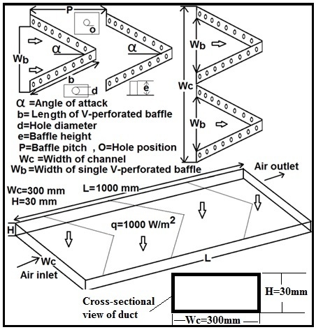
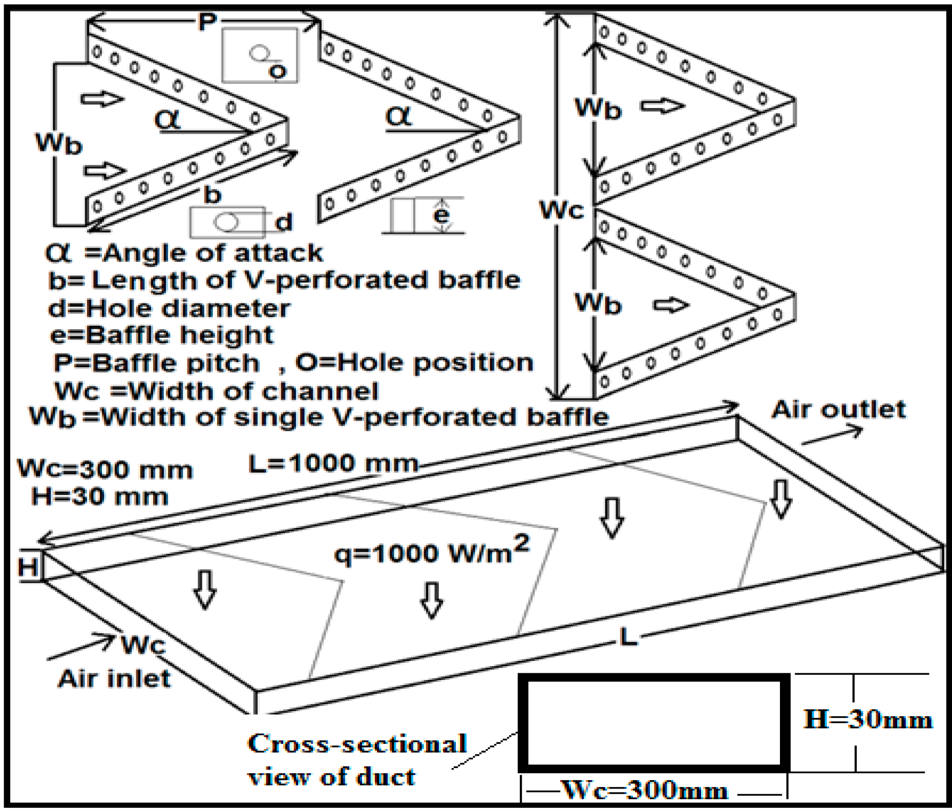
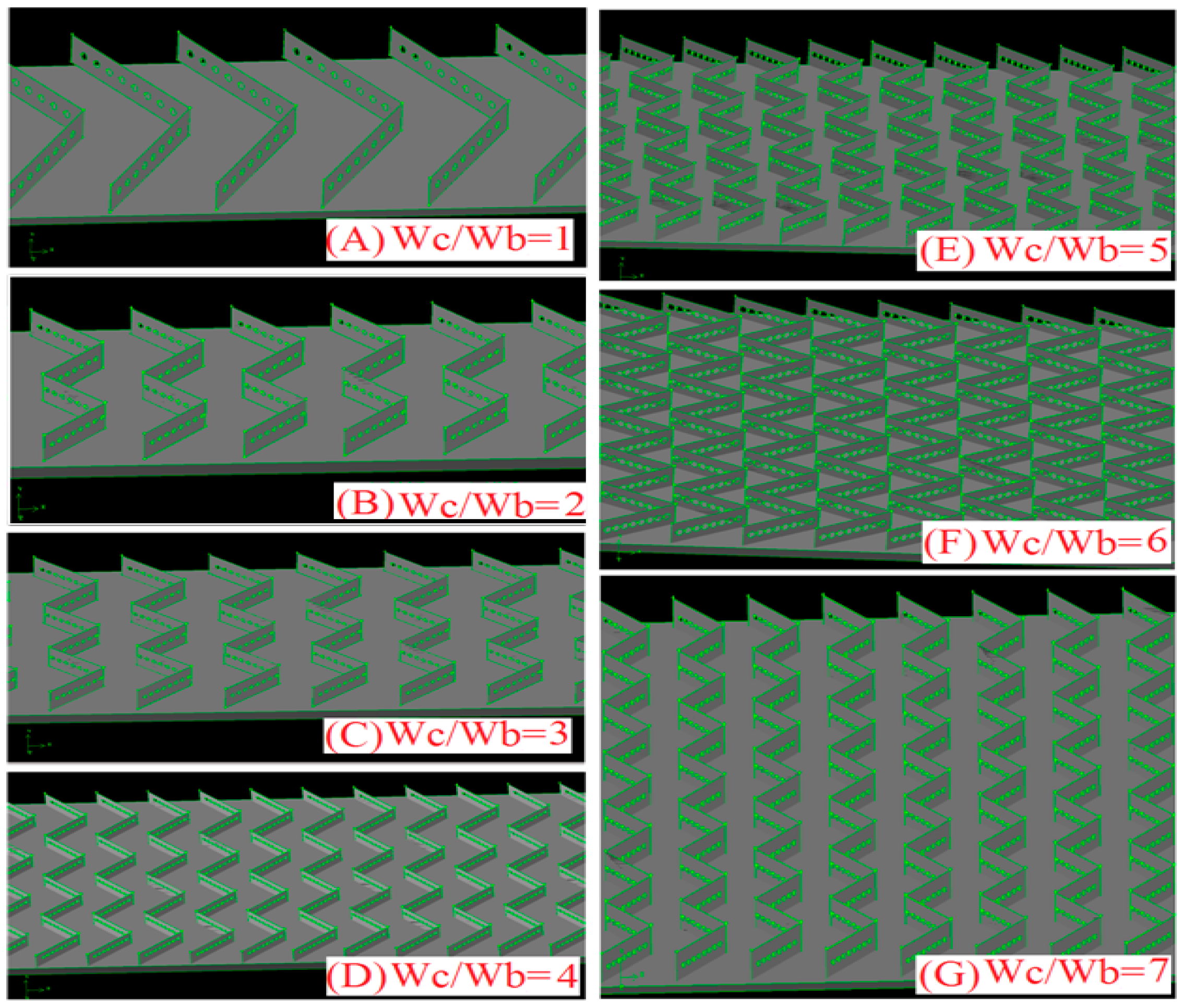
2.1. Description of Computational Model
2.2. Governing Equations
2.3. Grid Independency Test
2.4. Selection of Turbulence Model
2.5. Solution Method
2.6. Data Reduction
3. Results and Discussion
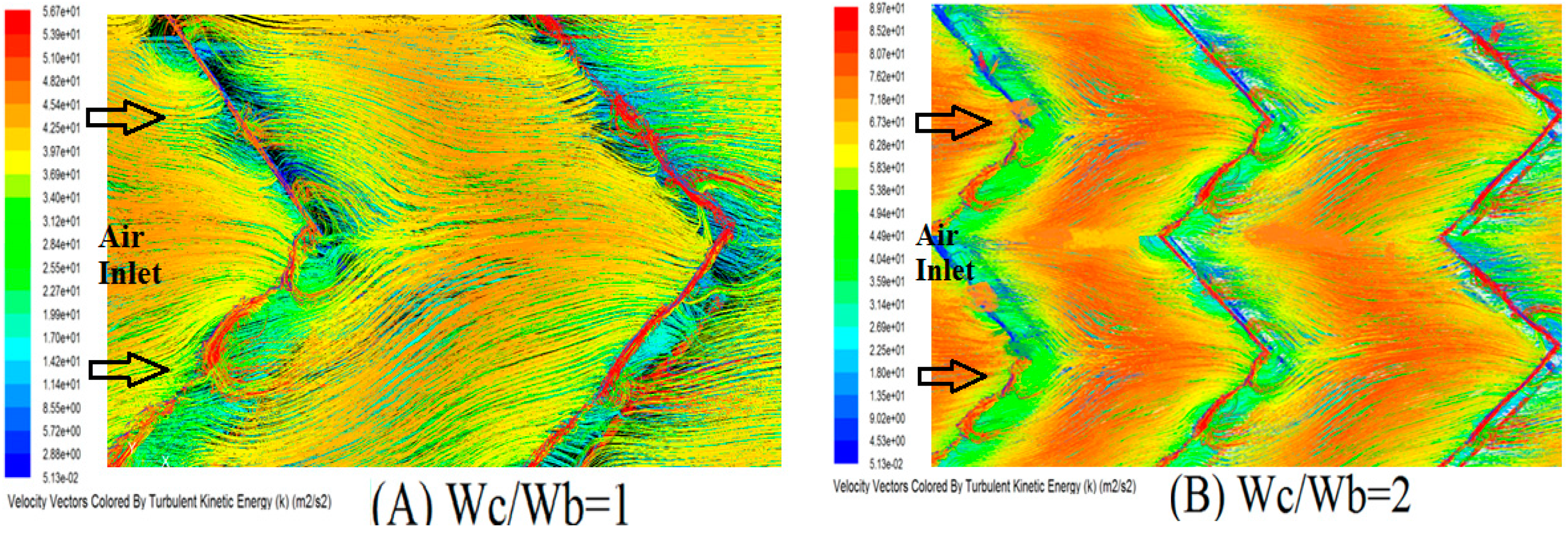
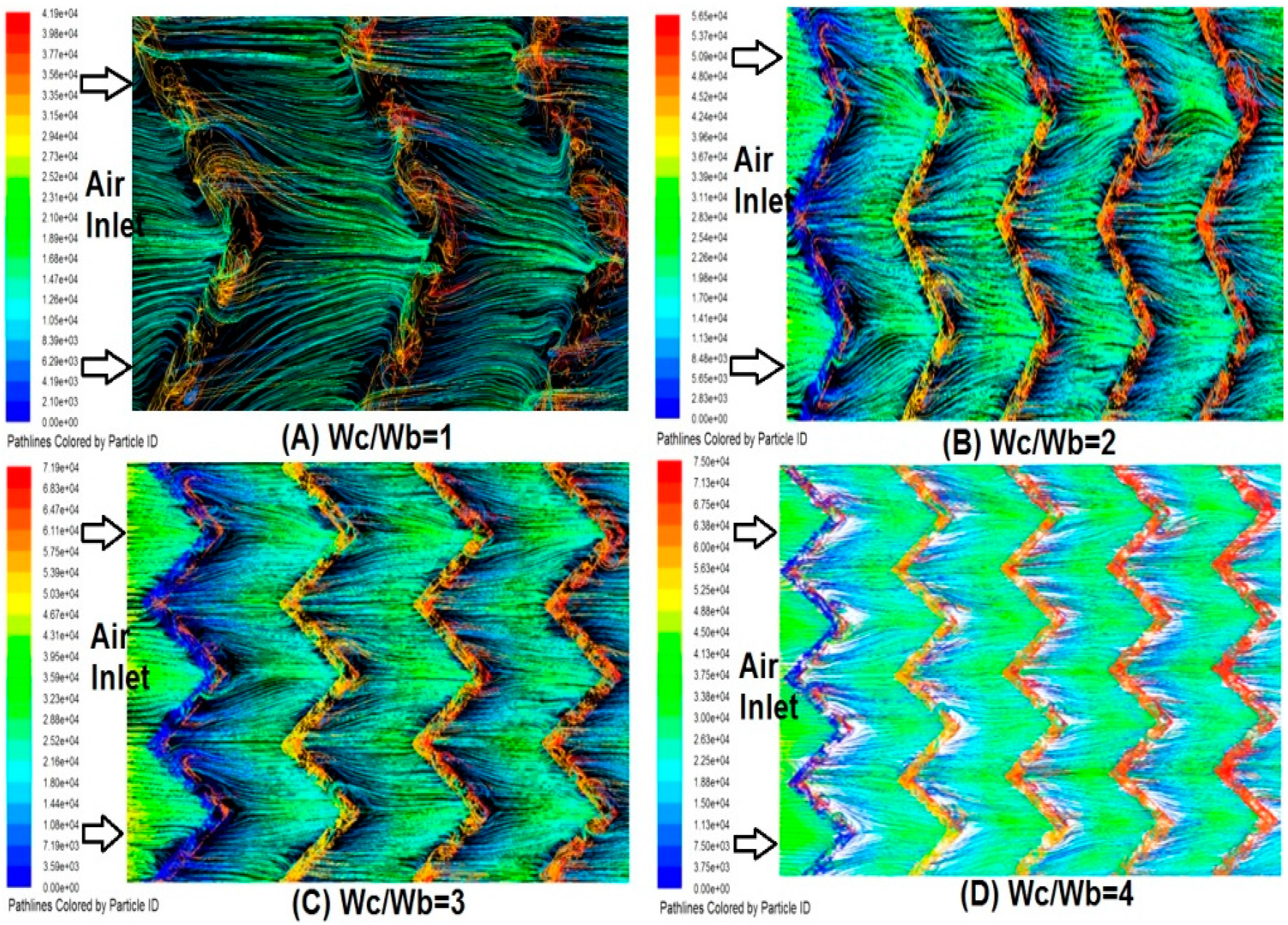
3.1. Heat Transfer and Fluid Flow
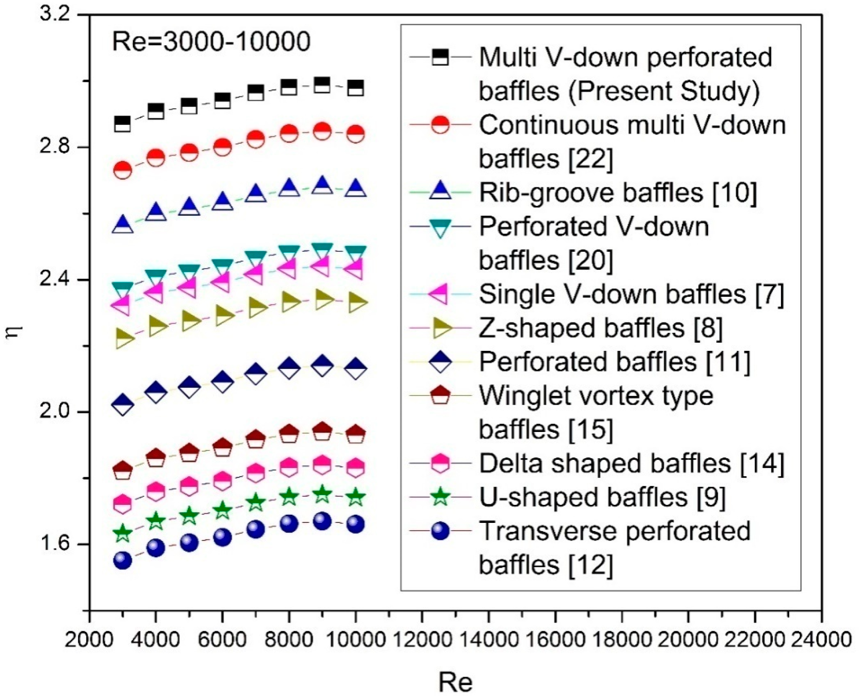
3.2. Thermo-Hydraulic Performance
4. Comparison Computational Fluid Dynamics Results with Experimental Data
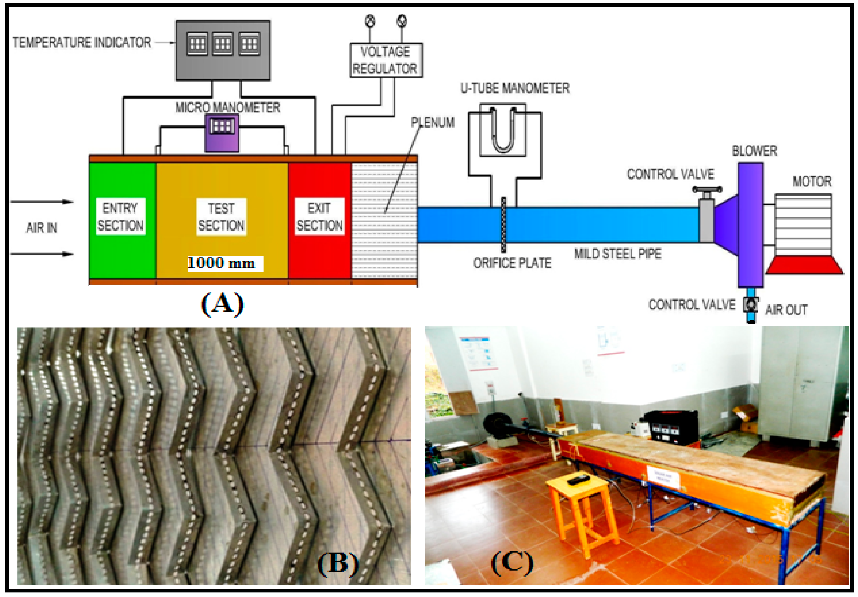
4.1. Experimental Setup Details
4.2. Uncertainty Analysis
| Mass flow rate (ma) | 2.67% |
| Reynolds number (Re) | 5.87% |
| Heat transfer coefficient (ht) | 6.23% |
| Average Nusselt number (Nuave) | 5.98% |
| Average friction factor (fave) | 4.18% |
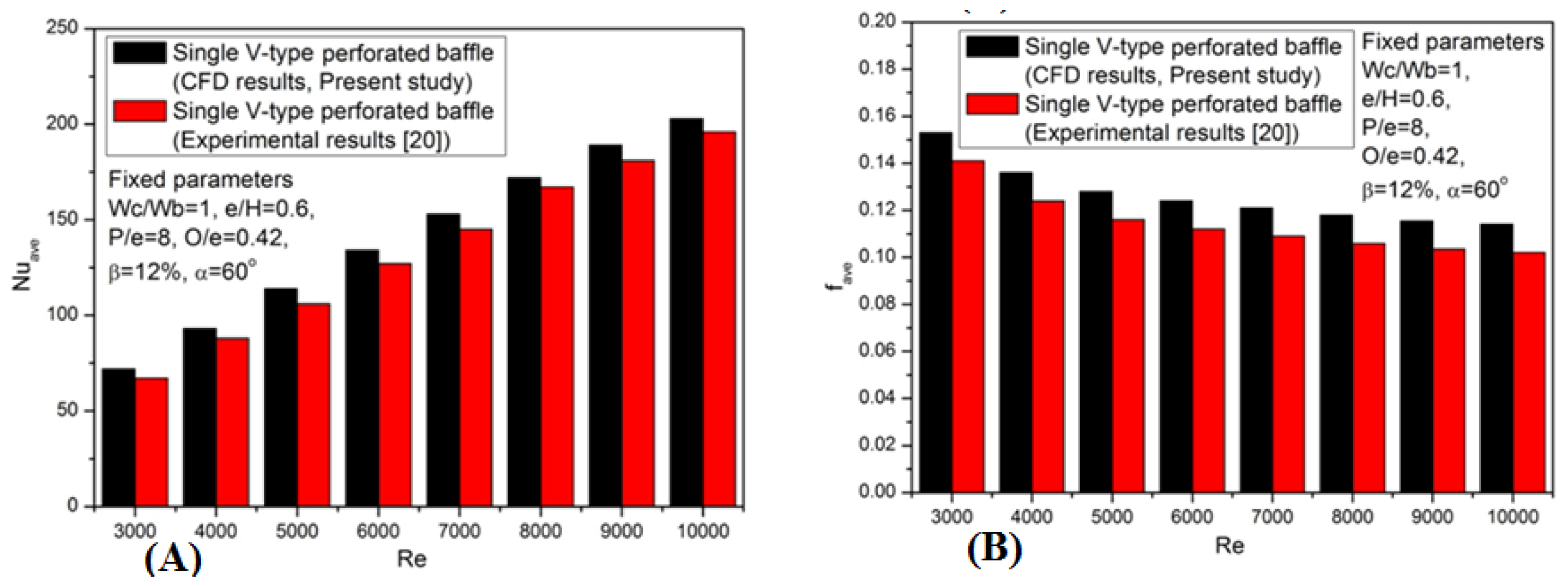
4.3. Validation of Computational Fluid Dynamics Results Using Experimental Data
5. Conclusions
Acknowledgements
Conflicts of Interest
Nomenclature
| B | Length of the baffle, m |
| Cp | Specific heat of air, J/kgK |
| D | Hydraulic diameter of channel, m |
| d | Hole diameter of perforated baffles, m |
| e | Baffle height, m |
| e/H, e/D | Relative baffle height |
| f | Friction factor of baffle roughened wall |
| fave | Average friction factor of baffle roughened wall |
| fsave | Average friction factor of smooth channel |
| H | Height of channel, m |
| ht | Convective heat transfer, W/m2K |
| k | Turbulent kinetic energy, m2/s2 |
| Ka | Thermal conductivity of air, W/mK |
| L1 | Axial pitch length, m |
| Lt | Length of test section, m |
| ma | Mass flow rate of fluid, kg/s |
| n | Number of drilled holes |
| Nu | Nusselt number for baffle roughened wall |
| Nus | Nusselt number for smooth wall |
| Nuave | Average Nusselt number for baffle roughened wall |
| Nusave | Average Nusselt number for without baffle wall |
| O | Hole location from bottom of baffle, m |
| O/e | Relative baffle hole location |
| P | Distance between baffles, m |
| P/e | Relative baffles pitch |
| p | Pressure, Pa |
| Pr | Prandtl number |
| Prt | Turbulent Prandtl number |
| q | Heat flux, W/m2 |
| Qu | Useful heat gain, W |
| Re | Reynolds number |
| T | Temperature, K |
| Tf | Average temperature of fluid, K |
| Ti | Inlet temperature of fluid, K |
| To | Outlet temperature of fluid, K |
| Tp | Plate temperature of fluid, K |
| ui | Velocity in -direction, m/s |
| Overall velocity vector, m/s | |
| V | Velocity of air, m/s |
| Wc/H | Channel aspect ratio |
| Wc | Width of passage, m |
| Wb | Width of a single V-perforated baffle, m |
| Wc/Wb | Relative baffles width |
| x | Axial coordinate, m |
| y+ | Dimensionless distance from walls |
| (Δp)d | Pressure drop crossways test section, Pa |
| (Δp)o | Pressure drop crossways orifice plate, Pa |
Greek Symbols
| α | Flow attack angle, degree |
| β | Open area ratio, % |
| μ | Dynamic viscosity, Ns/m2 |
| μt | Turbulent viscosity, Ns/m2 |
| ρ | Density, kg/m3 |
| φ | Half angle of baffle tip, degree |
| η | Thermo-hydraulic performance parameter |
| ԑ | Turbulent kinetic energy dissipation rate, m2/s3 |
| Cμ, Cԑ1, Cԑ2 | RNG k-ε model constant |
Subscript
| CFD | Computational fluid dynamics |
| SAH | Solar air heater |
References
- Kumar, A.; Kim, M.-H. Numerical optimization of solar air heaters having different types of roughness shapes on the heated plate—Technical note. Energy 2014, 72, 731–738. [Google Scholar] [CrossRef]
- Djamel, S.; Houari, A.; Redouane, B.; Youcef, K. Enhancement of heat transfer in a rectangular channel with perforated baffles. Appl. Therm. Eng. 2016, 101, 156–164. [Google Scholar]
- Kumar, R.; Chauhan, C.; Muneesh, S.; Ashutosh, S.; Kumar, A. Experimental investigation of effect of flow attack angle on thermohydraulic performance of air flow in a rectangular channel with discrete V-pattern baffle on the heated plate. Adv. Mech. Eng. 2016, 8, 1–12. [Google Scholar] [CrossRef]
- Kumar, A.; Kim, M.-H. Convective heat transfer enhancement in solar air channels. Appl. Therm. Eng. 2015, 89, 239–261. [Google Scholar] [CrossRef]
- Kumar, A.; Saini, R.P.; Saini, J.S. An experimental investigation of enhanced heat transfer due to a gap in a continuous multiple V-rib arrangement in a solar air channel. J. Enhanc. Heat Trans. 2014, 21, 21–49. [Google Scholar] [CrossRef]
- Won, S.Y.; Burgess, N.K.; Peddicord, S.; Ligrani, P.M. Spatially resolved surface heat transfer for parallel rib turbulators with 45 deg orientations including test surface conduction analysis. J. Heat Transf. 2004, 126, 193–201. [Google Scholar] [CrossRef]
- Khanoknaiyakarn, C.; Kwankaomeng, S.; Promvonge, P. Thermal performance enhancement in solar air heater channel with periodically V-shaped baffles. In Proceedings of the International Conference on Utility Exhibition on Power and Energy Systems: Issues and Prospectus for Asia (ICUE), Pattaya City, Thailand, 28–30 September 2011; pp. 1–6.
- Sriromreun, P.; Thianpong, C.; Promvonge, P. Experimental and numerical study on heat transfer enhancement in a channel with Z-shaped baffles. Int. Commun. Heat Mass Transf. 2012, 39, 945–952. [Google Scholar] [CrossRef]
- Bopche, S.B.; Tandale, M.S. Experimental investigation on heat transfer and frictional characteristics of a turbulator roughened solar air heater channel. Int. J Heat Mass Transf. 2009, 52, 2834–2848. [Google Scholar] [CrossRef]
- Skullong, S.; Kwankasmeng, S.; Thianpong, C.; Promvonge, P. Thermal performance of turbulent flow in a solar air heater channel with rib-groove turbulators. Int. Comm. Heat Mass Transf. 2014, 50, 34–43. [Google Scholar] [CrossRef]
- Karwa, R.; Maheshwari, B.K. Heat transfer and friction in an asymmetrically heated rectangular channel with half and fully perforated baffles at different pitches. Int. Commun. Heat Mass Transf. 2009, 36, 264–268. [Google Scholar] [CrossRef]
- Shin, S.; Kwak, J.S. Effect of hole shape on the heat transfer in a rectangular channel with perforated blockage walls. J. Mech. Sci. Tech. 2008, 22, 1945–1951. [Google Scholar] [CrossRef]
- Zhou, G.; Ye, Q. Experimental investigations of thermal and flow characteristics of curved trapezoidal winglet type vortex generators. Appl. Therm. Eng. 2012, 37, 241–248. [Google Scholar] [CrossRef]
- Bekele, A.; Mishra, M.; Dutta, S. Effects of delta-shaped obstacles on the thermal performance of solar air heater. Adv. Mech. Eng. 2011, 3. [Google Scholar] [CrossRef]
- Chompookham, T.; Thianpong, C.; Kwankaomeng, S.; Promvonge, P. Heat transfer augmentation in a wedge ribbed channel using winglet vortex generators. Int. Commun. Heat Mass Transf. 2010, 37, 163–169. [Google Scholar] [CrossRef]
- Abene, A.; Dubois, V.; Ray, M.L.; Ouagued, A. Study of a solar air flat plate collector: Use of obstacles and application for the drying of grape. J. Food Eng. 2004, 65, 15–22. [Google Scholar] [CrossRef]
- Ozgen, F.; Esen, M.; Esen, H. Experimental investigation of thermal performance of a double-flow solar air heater having aluminum cans. Renew. Energy 2009, 34, 2391–2398. [Google Scholar] [CrossRef]
- Thianpong, C.; Yongsiri, K.; Nanan, K.; Eiamsa-ard, S. Thermal performance evaluation of heat exchangers fitted with twisted ring turbulators. Int. Commun. Heat Mass Transf. 2012, 39, 861–868. [Google Scholar] [CrossRef]
- Eiamsa-ard, S.; Wongcharee, K.; Eiamsa-ard, P.; Thianpong, C. Heat transfer enhancement in a tube using delta-winglet twisted tape insets. Appl. Therm. Eng. 2010, 30, 310–318. [Google Scholar] [CrossRef]
- Chamoli, S.; Thakur, N.S. Correlations for solar air heater channel with V-shaped perforated baffles as roughness elements on absorber plate. Int. J. Sustain. Energy 2013, 35, 1–20. [Google Scholar] [CrossRef]
- Alam, T.; Saini, R.P.; Saini, J.S. Experimental investigation of thermohydraulic performance of a rectangular solar air heater duct equipped with V-shaped perforated blocks. Adv. Mech. Eng. 2014, 6. [Google Scholar] [CrossRef]
- Tamna, S.; Skullong, S.; Thianpong, C.; Promvonge, P. Heat transfer behaviors in a solar air heater channel with multiple V-baffle vortex generators. Sol. Energy 2014, 110, 720–735. [Google Scholar] [CrossRef]
- Gawande, V.B.; Dhoble, A.S.; Zodpe, D.B. CFD analysis to study effect of circular vortex generator placed in inlet section to investigate heat transfer aspects of solar air heater. Sci. World J. 2014, 2014. [Google Scholar] [CrossRef] [PubMed]
- Promvonge, P.; Jedsadaratanachai, W.; Kwankaomeng, S. Numerical study of laminar flow and heat transfer in square channel with 30° inline angled baffle turbulators. Appl. Therm. Eng. 2010, 30, 1292–1303. [Google Scholar] [CrossRef]
- Garg, A.; Dhingra, S.; Singh, G. CFD analysis of laminar heat transfer in a channel provided with baffles: Diamond shaped baffles of different angle and rectangle. Int. J. Enhanc. Res. Sci. Tech. Eng. 2014, 7, 267–276. [Google Scholar]
- Jedsadaratanachai, W.; Boonloi, A. Effect of blockage ratio and pitch ratio on thermal performance in a square channel with 30° double V-baffles. Case Stud. Therm. Eng. 2014, 4, 118–128. [Google Scholar] [CrossRef]
- Yadav, A.; Samant, T.; Varshney, L. A CFD based analysis of solar air heater having V-shaped perforated blocks on absorber plate. Int. Res. J. Eng. Tech. 2015, 2, 822–829. [Google Scholar]
- Yadav, S.; Bhagoria, J.L. A numerical investigation of square sectioned transverse rib roughened solar air heater. Int. J. Therm. Sci. 2014, 79, 111–131. [Google Scholar] [CrossRef]
- Karmare, S.V.; Tikekar, A.N. Analysis of fluid flow and heat transfer in a grit roughened surface solar air heater using CFD. Sol. Energy 2010, 84, 409–417. [Google Scholar] [CrossRef]
- Kumar, S.; Saini, R.P. CFD based performance analysis of a solar air heater duct provided with artificial roughness. Renew. Energy 2009, 34, 1285–1291. [Google Scholar] [CrossRef]
- Soi, A.; Singh, R.; Bhushan, B. Effect of roughness element pitch on heat transfer and friction characteristics of artificially roughened solar air heater duct. Int. J. Adv. Eng. Tech. 2010, 3, 339–346. [Google Scholar]
- Yadav, S.; Bhagoria, J.L. A CFD based thermo-hydraulic performance analysis of an artificially roughened solar air heater having equilateral triangular sectioned rib roughness on the absorber plate. Int. J. Heat Mass Transf. 2014, 70, 1016–1039. [Google Scholar] [CrossRef]
- Singh, S.; Singh, B.; Hans, V.S.; Gill, R.S. CFD (computational fluid dynamics) investigation on Nusselt number and friction factor of solar air heater duct roughened with non-uniform cross-section transverse rib. Energy 2015, 84, 509–517. [Google Scholar] [CrossRef]
- Kumar, A.; Kim, M.-H. Effect of roughness width ratios in discrete multi V-rib with staggered rib roughness on overall thermal performance of solar air channel. Sol. Energy 2015, 119, 399–414. [Google Scholar] [CrossRef]
- Fluent 6.3 User’s Guide; Fluent Inc.: Lebanon, NH, USA, 2006.
- Kumar, A.; Kim, M.-H. Heat transfer and fluid flow characteristics in air duct with various V-pattern rib roughness on the heated plate: A comparative study. Energy 2016, 103, 75–85. [Google Scholar] [CrossRef]
- Webb, R.L.; Eckert, E.R.G. Application of rough surface to heat exchanger design. Int. J. Heat Mass Transf. 1972, 15, 1647–1658. [Google Scholar] [CrossRef]
- Klein, S.J.; McClintock, A. Describing uncertainties in single-sample experiments. Mech. Eng. 1953, 75, 3–8. [Google Scholar]


| S.N. | Baffle Shapes | Parameter Ranges | Principle Findings |
|---|---|---|---|
| 1 | 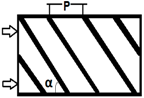 Angled baffles (Won et al. [6]) | e/D = 0.078–0.086, P/e = 10–14, α = 45°–60°, Re = 9000–76,000 | Respective Nuave and fave augmentations of 3.16 and 3.56 times were reported over a smooth rectangular channel. |
| 2 | 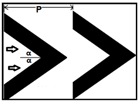 V-shaped baffles (Khanoknaiyakarn et al. [7]) | e/H = 0.2–0.4, P/e = 3-8, Re = 5000–25,000 | Respective Nuave and fave augmentations of 4.05 and 4.32 times were reported over a smooth rectangular channel. These studies have shown that V-shaped baffles perform better than angled baffles. |
| 3 | 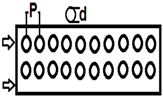 Perforated baffles (Karwa and Maheshwari [11]) | e/D = 0.495, P/e = 7.21–28.84, β = 26%–46.8%, Re = 2700–11,150 | Respective Nuave and fave augmentations of 3.87 and 4.12 times were reported over a smooth rectangular channel. |
| 4 |  Transverse perforated block baffles (Shin and Kwak [12]) | e/D = 1.0, Wc/H = 7.5, Re = 20,000–40,000 | Respective Nuave and fave augmentations of 3.98 and 4.2 times were reported over a smooth rectangular channel. |
| 5 |  Delta shaped baffles (Bekele et al. [14]) | e/H = 0.5, β = 45°, α = 20° | Respective Nuave and fave augmentations of 3.67 and 3.89 times were reported over a smooth rectangular channel. |
| 6 | 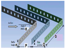 Single, perforated, V- shaped baffles (Chamoli and Thakur [20]) | e/H = 0.285–0.6, P/e = 2–7, β = 12%–14%, α = 60°, Re = 3800–19,000 | Respective Nuave and fave augmentations of 4.78 and 5.12 times were reported over a smooth rectangular channel. V-shaped perforated baffles perform better than angled and simple V-shaped baffles. |
| 7 |  Single V-perforated shaped blocks (Alam et al. [21]) | e/H = 0.4–1.0, P/e = 4–12, β = 5%–25%, α = 60°, Re = 2000–20,000 | Respective Nuave and fave augmentations of 4.98 and 5.04 times were reported over a smooth rectangular channel. These studies have shown that V-shaped perforated blocks perform better than angled and simple V-shaped baffles. |
| 8 |  Continuous, multi V-shaped baffles (Tamna et al. [22]) | e/H = 0.25, P/e = 5–12, α = 45°, Re = 4000–21,000 | Respective Nuave and fave augmentations of 6.28 and 6.55 times were reported over a smooth rectangular channel. These studies have shown that multi V-shaped baffles perform better than other baffles. |
| S.N. | Baffle Shapes | Parameter Ranges | Principle Findings |
|---|---|---|---|
| 1 |  Transverse baffles (Gawande et al. [23]) | P/e = 10–25, e/D = 0.03, Re = 3800–18,000 | Respective Nuave and fave augmentations of 2.98 and 3.14 times were reported over a smooth rectangular channel. |
| 2 |  Angled baffles (Promvonge et al. [24]) | e/H = 0.2–0.5, L1/H = 1–2, α = 30°, Re = 200–1000 | Respective Nuave and fave augmentations of 3.45 and 3.67 times were reported over a smooth rectangular channel. |
| 3 |  Diamond shape (Garg et al. [25]) | e/H = 0.5–1.0, φ = 5°–35°, Re = 100–600 | Respective Nuave and fave augmentations of 3.45 and 3.59 times augmentation in heat transfer and pressure drop were reported over a smooth rectangular channel. |
| 4 |  V-shaped baffles (Jedsadaratanachai et al. [26]) | e/H = 0.05–0.25, L1/H = 1–2, Α = 30°, Re = 100–1200 | Respective Nuave and fave augmentations of 4.11 and 4.39 times augmentation in heat transfer and pressure drop were reported over a smooth rectangular channel. |
| 5 |  Single V-down perforated baffles (Yadav et al. [27]) | e/H = 0.4–1.0, P/e = 4–12, β = 5%–25%, α = 60°, Re = 2000–20,000 | Respective Nuave and fave augmentations of 4.62 and 4.84 times augmentation in heat transfer and pressure drop were reported over a smooth rectangular channel. |
| S.N. | Parameters | Ranges/Values |
|---|---|---|
| 1 | Relative width ratio (Wc/Wb) | 1.0–7.0 |
| 2 | Relative height ratio (e/H) | 0.6 |
| 3 | Relative pitch ratio (P/e) | 8.0 |
| 4 | Relative hole position (O/e) | 0.42 |
| 5 | Open area ratio (β) | 12% |
| 6 | Angle of attack (α) | 60° |
| 7 | Reynolds number (Re) | 3000–10,000 |
| 8 | Uniform heat flux (q) | 1000 W/m2 |
| 9 | Prandtl number (Pr) | 0.71 |
| 10 | Duct aspect ratio (Wc/H) | 10 |
© 2016 by the authors; licensee MDPI, Basel, Switzerland. This article is an open access article distributed under the terms and conditions of the Creative Commons Attribution (CC-BY) license (http://creativecommons.org/licenses/by/4.0/).
Share and Cite
Kumar, A.; Kim, M.-H. Thermal Hydraulic Performance in a Solar Air Heater Channel with Multi V-Type Perforated Baffles. Energies 2016, 9, 564. https://doi.org/10.3390/en9070564
Kumar A, Kim M-H. Thermal Hydraulic Performance in a Solar Air Heater Channel with Multi V-Type Perforated Baffles. Energies. 2016; 9(7):564. https://doi.org/10.3390/en9070564
Chicago/Turabian StyleKumar, Anil, and Man-Hoe Kim. 2016. "Thermal Hydraulic Performance in a Solar Air Heater Channel with Multi V-Type Perforated Baffles" Energies 9, no. 7: 564. https://doi.org/10.3390/en9070564