Article

TBM/MTM for HTS-FNSF: An Innovative Testing Strategy to Qualify/Validate Fusion Technologies for U.S. DEMO

1
Department of Engineering Physics, University of Wisconsin-Madison, 1500 Engineering Drive, Madison, WI 53706, USA
2
Oak Ridge National Laboratory, P.O. Box 2008, Oak Ridge, TN 37831, USA
3
Princeton Plasma Physics Laboratory, 100 Stellarator Road, Princeton, NJ 08540, USA
*
Author to whom correspondence should be addressed.
Energies 2016, 9(8), 632; https://doi.org/10.3390/en9080632
Submission received: 29 April 2016 / Revised: 13 July 2016 / Accepted: 27 July 2016 / Published: 11 August 2016
(This article belongs to the Special Issue Fusion Power)

Abstract

:
The qualification and validation of nuclear technologies are daunting tasks for fusion demonstration (DEMO) and power plants. This is particularly true for advanced designs that involve harsh radiation environment with 14 MeV neutrons and high-temperature operating regimes. This paper outlines the unique qualification and validation processes developed in the U.S., offering the only access to the complete fusion environment, focusing on the most prominent U.S. blanket concept (the dual cooled PbLi (DCLL)) along with testing new generations of structural and functional materials in dedicated test modules. The venue for such activities is the proposed Fusion Nuclear Science Facility (FNSF), which is viewed as an essential element of the U.S. fusion roadmap. A staged blanket testing strategy has been developed to test and enhance the DCLL blanket performance during each phase of FNSF D-T operation. A materials testing module (MTM) is critically important to include in the FNSF as well to test a broad range of specimens of future, more advanced generations of materials in a relevant fusion environment. The most important attributes for MTM are the relevant He/dpa ratio (10–15) and the much larger specimen volumes compared to the 10–500 mL range available in the International Fusion Materials Irradiation Facility (IFMIF) and European DEMO-Oriented Neutron Source (DONES).

Graphical Abstract

1. Introduction

Design teams in the U.S. and abroad tackled the qualification/validation problem using different approaches, but with the common goal of developing a testing facility before the demonstration plant (DEMO) to help qualify and/or validate technologies for key fusion components (blanket, divertor, vacuum vessel, and magnet) and for the overarching structural and functional materials. In the U.S., the venue for such activities is the proposed Fusion Nuclear Science Facility (FNSF). It is the only U.S. facility with the combined radiation damage and fusion environmental conditions (14 MeV neutrons, high operating temperatures, strong magnetic fields, etc.) needed for engineering qualification of materials and components prior to the DEMO design and construction.
The two-machine pathway, shown at the top of Figure 1, is the preferred U.S. pathway to commercial power plant where the first machine would be an FNSF (that could be based on the tokamak, spherical tokamak, or stellarator concept [1]), followed by a DEMO envisioned to be identical in content (i.e., same confinement concept, materials and technologies), but varying in performance level (such as the fusion power and availability). An alternate approach is to build a DEMO as a single step to a power plant using near-term physics and technology as in the International Thermonuclear Experimental Reactor (ITER) [2]. This approach (advocated by Europe, Japan, and Korea) would be a multi-phase operation, where Phase-I would have an FNSF-type mission and the following Phase-II would rebuild the facility to be a true DEMO [3,4,5]. The third approach proposed by China is to build an engineering test facility (CFETR) [6] before DEMO—similar to the U.S. pathway but with a different mission, goals, technologies, and testing strategy. As noted, all approaches are targeting the same goal of building the first power plant by 2050 (or beyond), but differ in the levels of risk (two-step approach or single machine) and degree of extrapolation beyond ITER (using near-term or more advanced physics and technology for DEMO and power plant).
The proposed FNSF is a truly integrated high quality test facility. Prior to DEMO construction, fusion power plant components and subsystems must be tested in a dedicated facility with a fusion-relevant environment. A number of proposals have been made in the U.S. for an FNSF type device [7,8,9,10,11] to enable integrated testing and development of fusion technologies under prototypical fusion conditions. Such tokamak and spherical tokamak (ST) facilities will display the complex integration of fusion components and subsystems in relevant fusion environment: 14 MeV neutrons, surface and volumetric heating, helium and hydrogen generation in materials, relevant stresses, high pressures and temperatures with significant gradients, and strong magnetic fields. Due to the lack of readily available external sources of tritium in the U.S. and the prohibitive expenses of purchasing tritium (T), any FNSF must breed all the T needed for its operation.
This paper focuses on the most recent ST-based FNSF [8] that has been developed in recent years through a national collaborative effort led by the U.S. Princeton Plasma Physics Laboratory. The ST is a leading candidate for an FNSF due to its potentially high neutron wall loading and modular configuration. High-temperature superconducting (HTS) magnets are potentially attractive for compact ST applications due to higher operating temperature (~40 k), which could reduce thermal shielding requirements and reduce magnet size relative to configurations with low-temperature superconductor (LTS) magnets [8]. However, the lower radiation tolerance of HTS requires an additional 5–10 cm of shielding relative to the more radiation-resistant LTS. The 3-m major radius HTS-FNSF design generates 560 MW of fusion power and 1.5 MW/m2 machine average neutron wall loading. This entails a peak neutron wall loading of ~2 MW/m2, producing significant neutron fluence (~6 MWy/m2) at the outboard (OB) midplane for blanket and materials testing during the 10-year operation. The design goal is to progressively increase the machine availability from 10% to 50% for an average of 30% over the facility lifetime. The maximum achievable displacement per atom (dpa) and He production are 60 dpa and 600 He atom part per million (appm), respectively, at the end of the 3.1 full power years (FPY) of operation [12]. Figure 2 shows a CAD drawing of the HTS-FNSF with 3-m major radius and 1.5-m minor radius. A thin inboard blanket (~10 cm) is necessary to achieve a tritium breeding ratio > 1. A vertical maintenance scheme has been developed where the blanket system and centerstack can be removed rapidly and independently.
This paper provides insight and justifications for innovative blanket and materials testing strategies that will lead to and qualify advanced subsystems for DEMO and power plants. It is desirable to have several testing modules on any FNSF to expose a wide range of material specimens and blanket concepts in a relevant fusion neutron environment. A separate materials testing module (MTM) is critically important to include in the FNSF as well to expose and test a broad range of newer materials (not yet qualified for use in the FNSF). The most important attributes for the MTM would be the fusion-relevant He/dpa ratio (10) and the much larger specimen volumes (up to 20 cm × 50 cm × 80 cm, mimicking the actual shape and volume of structural components)—much larger than the 10–500 mL specimens of currently proposed 14 MeV neutron sources. After irradiation, the tested materials could be contrasted with those of the International Fusion Materials Irradiation Facility (IFMIF) [13], the European DEMO-Oriented Neutron Source (DONES) [14], or other accelerator-based neutron environments, as discussed in Section 2. More advanced versions of the dual-cooled PbLi (DCLL) blanket along with ceramic breeder blankets could be tested in dedicated test blanket modules (TBM), as discussed in Section 3. Figure 3 displays the integration of a TBM (or MTM) port in one of the 20 HTS-FNSF OB sectors. Such ports will be located on the OB midplane (where the neutron flux peaks) and surrounded with the DCLL blanket that would breed the T fuel needed for plasma operation.

2. MTM and Main Attributes

An essential task for the U.S. materials community will be to provide further irradiation data, well before the start of construction of any FNSF, to confirm that the first generation (GEN-I) reduced-activation ferritic/martensitic (RAFM) alloys (such as the Japanese steel (F82H) and European steel (EUROFER)) [15] could survive at least 20 dpa at the first wall (FW). This confirmation could possibly be derived from irradiation experiments utilizing the spallation neutron source (SNS) experiment [16], the High Flux Isotope Reactor (HFIR) [17], and heavy ion facilities to partially simulate the fusion irradiation environment. The existing simulation experimental database [18,19] indicates that radiation damage begins to have significant effects on properties for damage levels of 20–30 dpa/200–300 appm helium. However, irradiation performance data derived from these facilities must be regarded as an approximate assessment of the dpa and helium levels that could be tolerated by the current GEN-I RAFMs.
Based on the fission experience, the development of higher performance materials will progress in stages. The future development of GEN-II RAFMs (based on nanostructured microstructures generated via conventional fabrication technologies) will provide higher creep strength sufficient to permit the extension of the operating regime up to ~650 °C. In addition, the microstructures of these alloys are being designed to provide more efficient trapping of helium and point defects to improve the overall tolerance to radiation damage. A further stage in the advancement of improved structural alloys is the development of nanostructured Oxide Dispersion Strengthened (ODS (NS)) alloys [20,21] containing 12%–14% chromium. In addition to providing even higher levels of radiation-damage tolerance via more efficient trapping of point defects and helium atoms, the exceptional thermal stability of their nano-scale microstructures would provide enhanced tolerance to off-normal temperature excursions during an accident.
The performance goals for the structural materials will be to survive the HTS-FNSF operation. A clear advantage of developing more radiation resistant structures is to allow the structure (and other materials) to survive higher fluence without property degradation, resulting in less frequent replacement of components and consequently less generation of radioactive waste, thus enabling higher plant availability in the DEMO and commercial power plant. A set of alloy development goals (for radiation damage tolerance and to expand the operating temperature window) should be considered in any FNSF for three classes of alloys:
  • GEN-I RAFMs (20 dpa/200 appm He). This would require the structure be replaced upon reaching 20 dpa after one FPY of HTS-FNSF operation;
  • GEN-II RAFMs (50 dpa/500 appm He) needed to be deployed for the structure to survive~2.5 FPY of HTS-FNSF operation;
  • ODS (NS) (65 dpa/650 appm He) needed to survive the entire 3.1 FPY of HTS-FNSF operation.
The suggested range of 50–65 dpa limits is not founded on any 14 MeV data, but rather they are credible goals that could be achieved with the right kind of R&D programs coupled with a 14 MeV neutron facility. Another important aspect to the high chromium ODS (NS) alloys is the potential for alloying with ~5 wt % aluminum (in addition to Zr or Hf) to improve the liquid metal (PbLi) corrosion resistance—an important aspect of the DCLL blanket. The ODS FeCrAl alloys [22] are currently being investigated at the Oak Ridge National Laboratory for possible PbLi applications at 700–800 °C.
The validation of the 50–65 dpa goals and the development of an engineering design database for FNSF are entirely dependent on the timely deployment of fusion relevant neutron facilities, such as IFMIF [13] and DONES [14]. However, the FNSF itself will provide the only opportunity to extend the understanding of materials behavior in the integrated multi-effects fusion environment, combining the fusion neutron spectrum, temperature and magnetic field gradients, cyclic operation, etc. To take advantage of this unique fusion neutron environment produced in the FNSF, it is proposed that a materials testing module be embedded in the outboard blanket of the HTS-FNSF (as shown in Figure 3) to contribute to the comprehensive multi-materials database with the potential to reach neutron exposures up to 60 dpa. A wide variety of materials and test specimens could be accommodated simultaneously. For example:
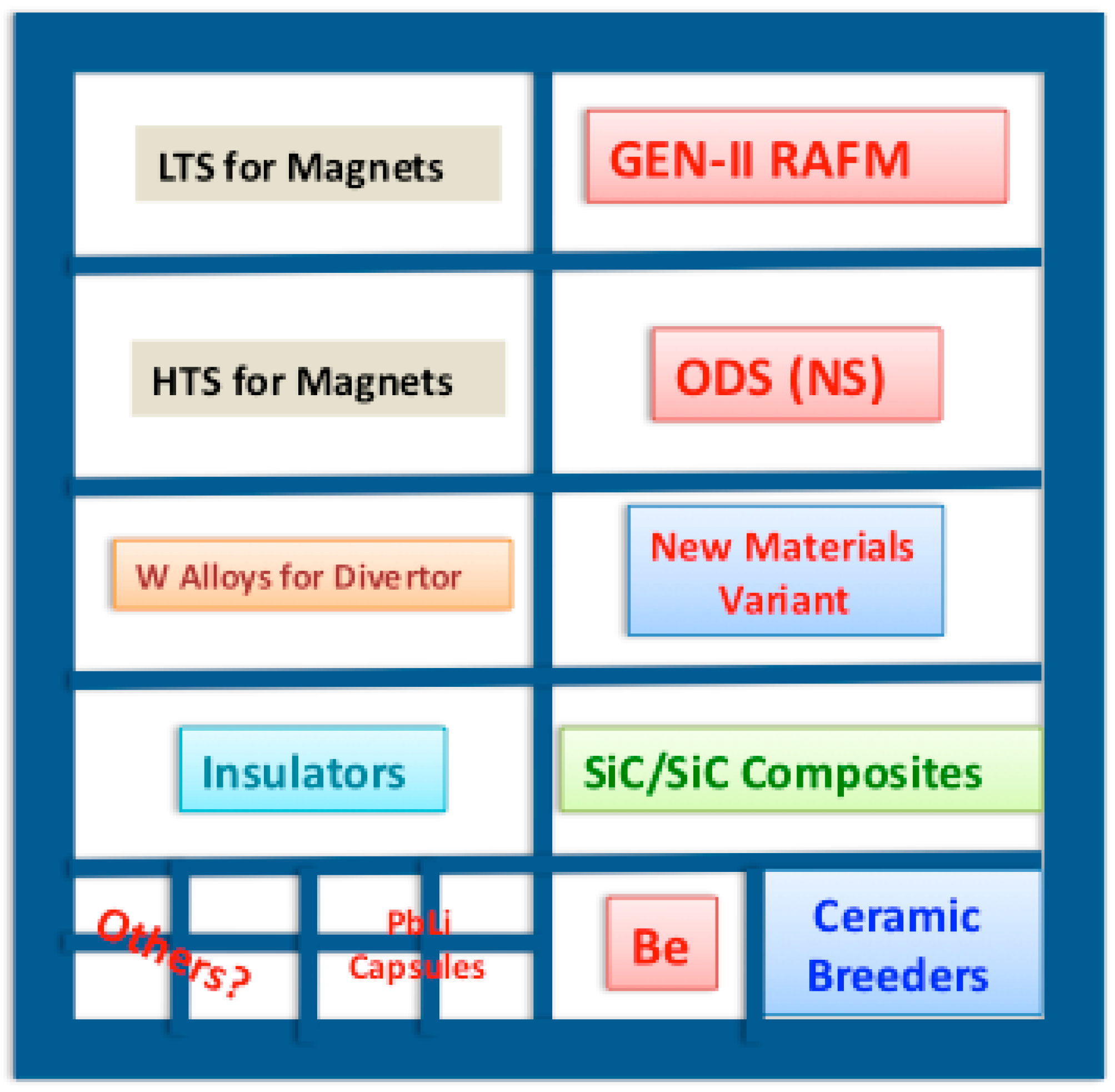
  • New generations of structural steels, if not tested before the FNSF, including:
    GEN-II RAFMs designed for operation up to 650 °C
    RAFM variants with reduced susceptibility to radiation-induced DBTT shifts for operating temperatures < 385 °C
    Nanostructured ODS steels (12%–14% Cr) with enhanced radiation damage tolerance and high temperature capability
  • Multi-material PbLi corrosion capsules
  • SiC/SiC composites for advanced blanket designs
  • Tungsten (W) alloys for divertor and stabilizing shells (W-TiC, W-La, W-K, W/W composites, Wolfram-Vacuum-Metalizing (WVM), etc.)
  • Low-temperature and high-temperature magnet materials: superconductors, jackets, insulators, etc.
  • New materials variants arising from:
    Continuing development of improved compositions/microstructures
    Application of advances in fabrication technologies (additive manufacturing, precision casting, joining technologies, etc.).
Figure 4 displays the proposed layout of material samples within ~1 m2 MTM. Samples within individual compartments are not structural, could be exposed to higher dpa compared to that of the full sector, and could vary in shapes, sizes, thicknesses, etc. The RAFM structural frame would be replaced upon reaching the dpa limit while some fraction of the specimen inventory would be re-installed after change outs in order to accumulate progressively higher damage levels and accelerate the qualification of materials for later stages of HTS-FNSF operation. Samples placed in close proximity to the FW will operate at moderate and high temperatures to mimic a wide range of operating conditions for ceramic breeder (Li4SiO4, Li2TiO3, Li2ZrO3) and DCLL blankets. Shielding blocks along with thermal insulators will be utilized to adjust the flux strength and spectrum for magnet samples placed at the back of the MTM to operate at low and high cryogenic temperatures (4 k–70 k).
As mentioned earlier, the data developed with continuous radiation sources (SNS, DONES, IFMIF, fission reactors, ion accelerators, etc.) are essential for developing the science-based understanding of neutron radiation damage phenomena that underpins the development of damage-resistant materials. Data from such facilities will also form the basis for developing the engineering database for designing and licensing FNSF. Meanwhile, the MTM on the HTS-FNSF is a complementary source of fusion neutron irradiation data in the actual fusion neutron spectrum, and is critical to quantifying the differences with accelerator-based exposure data. Table 1 compares several key parameters for existing and proposed pre-DEMO neutron sources. Detailed descriptions of facilities are available in the references.
The most important attributes for MTM would be the relevant He/dpa ratio and the much larger specimen volumes (up to 20 cm × 50 cm × 80 cm) compared to the limited 10–500 mL range available in the SNS/IFMIF/DONES/HFIR series of neutron sources. In summary, the MTM potentially provides a means of:
  • Testing in fusion relevant neutron environment with the correct He to dpa ratio of 10, H to dpa ratio of ~40, transmutant production rates, and primary knock-on atom (PKA) parameters.
  • Testing a range of specimen geometries (tubes, flat and curved plates, etc.).
  • Testing larger sized mechanical property specimens, particularly pressurized creep tubes and fracture toughness specimens with a range of section thicknesses and crack geometries.
  • Validation of data derived from highly miniaturized specimens irradiated in SNS/IFMIF/DONES/HFIR.
  • Carrying a higher multiplicity of test specimens for improved statistical analyses.
  • Conducting a critically important surveillance program to track materials performance using a range of specimen geometries to monitor radiation-induced changes in mechanical properties and dimensional stability of first wall, blanket and divertor plasma facing structural materials.
  • Evaluation and testing of welded/bonded joints with various geometries.
  • Irradiation testing of new material variants arising from continuing development of improved compositions and microstructures and from the application of advances in fabrication technologies (such as additive manufacturing, precision casting, alternative joining/bonding technologies, etc.).
  • Providing radiation effects data in a pulsed neutron environment and comparing behavior of identical materials irradiated in steady state 14 MeV neutron sources.

3. TBM Testing Strategy, Configuration, and Deliverables

Besides FNSF’s ability to predict the plasma performance and materials behavior under prototypical fusion conditions, there is a need to test more advanced version(s) of the DCLL blanket [23] along with a backup blanket and an alternate concept before DEMO construction. A backup blanket could be the He-cooled PbLi blanket [24] due to many similarities in configuration and a few differences, such as a semi-stagnant PbLi breeder operating at a lower temperature without SiC thermal/electric insulator. An alternate concept would be the helium-cooled ceramic breeder blanket [25] that could be tested in one or two TBMs.
In early 2011, we developed a novel, staged blanket testing strategy for any FNSF device that could operate in phases [26]. In 2013/2014, we tailored the strategy to the ST-FNSF design [27]. Later, further modifications have been made and applied to the most recent 2016 HTS-FNSF design in the ST series. In this HTS-FNSF, the blanket qualification will be accomplished during several operational phases with the objective of maturing 3–4 versions of the DCLL blanket concept, testing and enhancing their performance during each phase of the operation. In this strategy, the TBM serves as a “forerunner” for more advanced blanket versions. Since testing a number of full-size blanket sectors is judged mandatory for the qualification of any blanket concept, the more advanced version of the DCLL blanket, originally tested in the TBM, is later deployed as a full sector in subsequent phase(s) of HTS-FNSF to validate their characteristics and features for DEMO. As noted, this strategy reaches beyond the traditional testing mission of ITER that tests several blanket concepts only in TBMs at lower flux and fluence, but not in other modules [28].
As an essential requirement, the FNSF will have to remove the T from the blanket and TBMs, recover the T from all coolants, and detritiate all materials and areas that contain T. This ability is absolutely necessary to prepare for DEMO and for the realization of commercial fusion, whereas lesser facilities (like ITER [2]) will not satisfy this criterion. The first version (VER-I) of the DCLL blanket must be robust, highly reliable, operate at a lower temperature, and cover the entire space surrounding the TBMs and other diagnostics, heating, and current drive ports. To assure high reliability, sufficient margins to absolute limits (maximum structure temperatures, inter-phase temperatures to coolant, mechanical stresses, etc.) should all be incorporated in designing the VER-I blanket coupled with an extensive R&D blanket program [26,27].
The low temperature requirement suggests a GEN-I RAFM alloy operating temperature of 350–550 °C achievable with PbLi and He inlet/outlet temperature of 350/450 °C. The temperature distribution in the FW and blanket structure should be as uniform as possible to minimize the thermal stresses. A unique feature of the DCLL blanket is the need for a flow channel insert (FCI) to serve as an electric insulator to control magneto-hydrodynamic (MHD) pressure drop [23]. Since the operating temperature is not too high within the VER-I blanket, the FCI does not have to serve as a thermal insulator. In past studies, SiC was proposed for the FCI, serving as an electrical and thermal insulator. If such a SiC FCI [29] cannot be developed and qualified before operating the FNSF, a sandwich-like FCI made of RAFM/alumina/RAFM multilayer [30] could be employed only for the VER-I blanket. Figure 5 shows an isometric view of a typical DCLL blanket and a midplane cross section of the FNSF DCLL TBM that resembles to a great extent the HTS-FNSF OB blanket.
Several more advanced versions of the DCLL blanket concept could be tested first in the volume-limited TBMs, and then reconfigured as a full blanket for a sector in the next stage of FNSF operation. Figure 6 illustrates the steps involving TBM testing and then transitioning to full blanket for several generations of structural materials. To amplify this process, following a successful testing of the more advanced VER-II blanket in the TBM of Stage-1, this blanket will be manufactured and installed as full sectors in the next Stage-2 of HTS-FNSF. This process will repeat and, in each stage, the TBM and blanket operating conditions will improve incrementally. It is assumed that the advanced GEN-II RAFM structure and ODS (NS) alloys are employed everywhere in the more advanced versions of the full blanket to enhance the radiation lifetime and thermal conversion efficiency. The increased interface temperature between the steel and PbLi may require a solution for the PbLi/RAFM corrosion problem, in particular for the GEN-III RAFM alloys, before operating the HTS-FNSF. High degree of neutron flux symmetry at the TBM surface is highly desirable, as illustrated in Figure 7, in order to compare the blanket concept performance under the same operating conditions.
Assuming success, the last stage of operation will qualify the most advanced blanket concept for DEMO. As noted, the DCLL TBM serves as a “forerunner” to develop more advanced versions of the DCLL blanket technologies for VER-II, -III, -IV, and -V DCLL blanket systems, while the blanket is utilized for T breeding, qualification, and reliability growth testing. The combined testing results from the TBMs and blanket systems are essential to build high confidence and lower risk for successful operation of the most advanced blanket system for DEMO and future power plants. More specific operating conditions and structural requirements to develop several versions of DCLL blanket systems during the consecutive technology stages of HTS-FNSF follow:
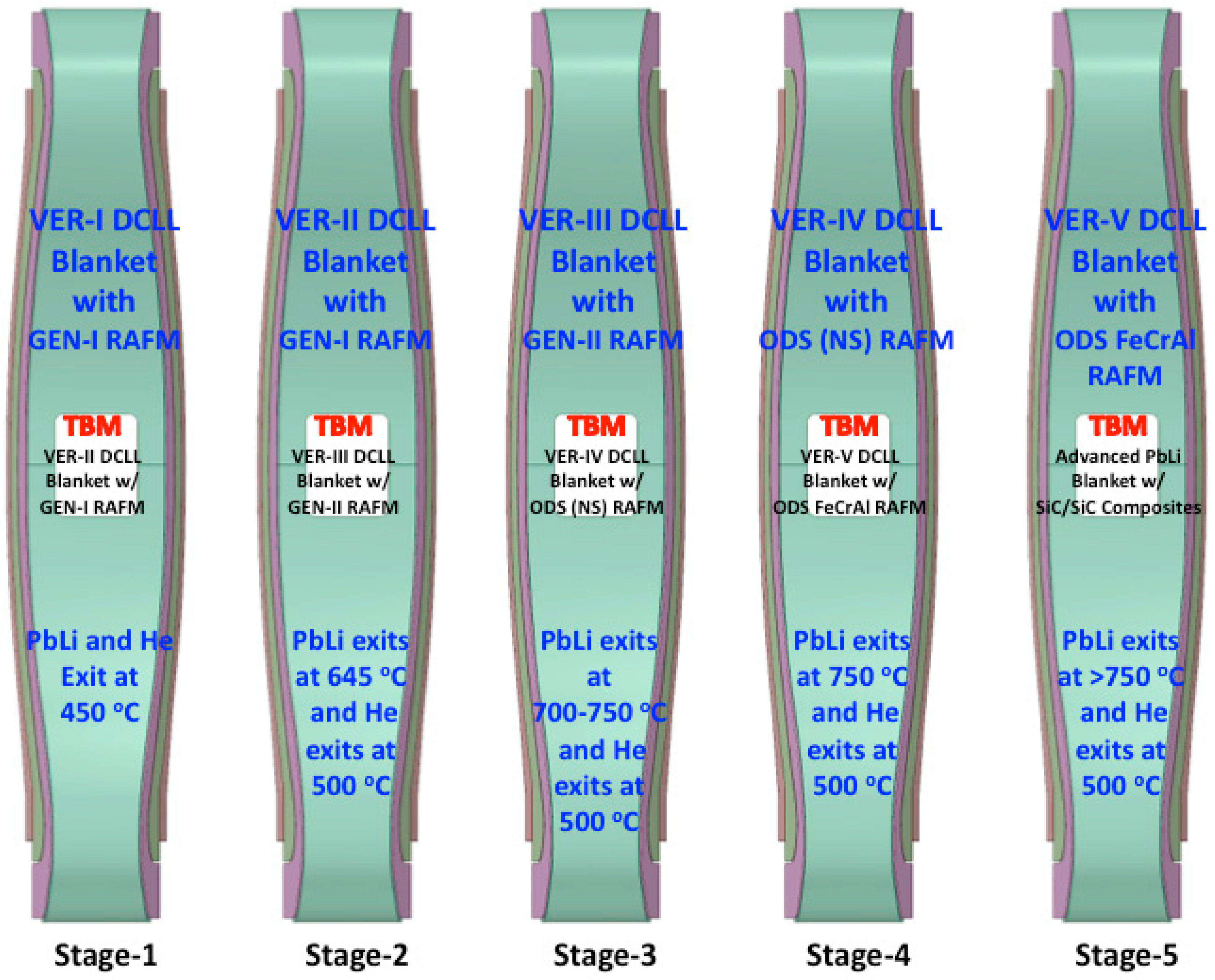
  • In Stage-1, VER-I low-temperature DCLL blanket: with GEN-I RAFM structure (F82H or EUROFER) operating at 350–550 °C, maximum PbLi and He exit temperature of 450 °C, and maximum interface steel/PbLi temperature of 450 °C.
  • In Stage-2, VER-II DCLL blanket first tested successfully in the TBM of Stage-1 and then installed in all sectors of Stage-2: DCLL blanket with GEN-I RAFM structure operating at 350–550 °C, PbLi inlet/outlet temperatures 460/645 °C, He inlet/outlet temperatures 380/470 °C, and maximum interface steel/PbLi temperature of 500 °C.
  • In Stage-3, VER-III DCLL blanket first tested successfully in the TBM of Stage-2 and then installed in all sectors of Stage-3: DCLL blanket with GEN-II RAFM structure operating at 600 °C, PbLi exit temperature of 700–750 °C, He exit temperature of 500 °C, and maximum interface steel/PbLi temperature > 500 °C.
  • In Stage-4, VER-IV DCLL blanket first tested successfully in the TBM of Stage-3 and then installed in all sectors of Stage-4: DCLL blanket with ODS (NS) structure operating at 700 °C, PbLi exit temperature of 750 °C, He exit temperature of 500 °C, and maximum interface steel/PbLi temperature > 500 °C.
  • In Stage-5, VER-V DCLL blanket first tested successfully in the TBM of Stage-4 and then installed in all sectors of Stage-5: DCLL blanket with the more radiation resistant, corrosion-resistant ODS FeCrAl structure operating at >700 °C. An option for the TBM of Stage-5 is to test the more advanced SiC/PbLi blanket concept of ARIES-AT [31]. This self-cooled PbLi blanket with SiC/SiC composite structure operating at 1000 °C offers higher thermal conversion efficiency, exceeding 55%.
This testing approach assumes positive TBM results, as tested technologies will be incorporated in the next more advanced version of the blanket to be installed in subsequent stages of HTS-FNSF operation. This means that we anticipate positive results by designing, fabricating, and building sectors out of more advanced versions of the DCLL blanket while testing materials in the MTM and blankets in TBMs as well as building the next generation of the TBMs. A strong R&D program combined with state-of-the-art predictive capability (extensive modeling and computer simulation) assures the success of blanket and materials testing in HTS-FNSF.
What are the TBM deliverables? The answer to this question has multiple facets. In the FNSF, the TBM serves as the breadboard prototype to test more advanced versions of the DCLL blanket and structural materials in relevant fusion environment. In other words, the TBM helps make the transition from an early version of the DCLL blanket (installed at the beginning of FNSF operation) to more advanced versions for later stages of operation through incremental changes to its operating conditions, utilizing more advanced materials for the structure and possibly for the FCI. Because the TBM always operates at different temperatures than the surrounding blanket, the TBM will have its own ancillary system. However, the tritium handling, extraction, and management are common systems between the DCLL TBM and blanket. Thus, the TBM along with the blanket will demonstrate the online recovery of T. If the overall T breeding ratio exceeds unity, the control of T production through the online adjustment of Li-6 enrichment [32] will be demonstrated as well.
During operation, the TBM will be heavily loaded with diagnostics for thermal, pressure, PbLi flow rate, and MHD measurements. The later is unique to the DCLL blanket. Because the TBM has a limited height (1 m) with reduced number of parallel poloidal PbLi channels compared to the full blanket, some may argue that it could be problematic to extrapolate the MHD result from the TBM to the full sector. Since the entire FNSF is a testing facility, the MHD effect could better be tested in the high-field, inboard side of the blanket during multi-stages of operation. Other data specific to the DCLL blanket include the behavior of the SiC flow channel inserts and the impact of changing the operating conditions (such as reducing the PbLi flow rate that leads to a higher outlet temperature) while utilizing more advanced structural materials. Such data are needed before a set of full sectors is fabricated.
Besides such experimental measurements, the validation of codes/software (for neutronics, radiation shielding, mechanism of materials activation, MHD, heat transfer, thermal hydraulics, T production/recovery/inventory, etc.) and theoretical predictions (for structural integrity and failure mechanism, life-limiting criteria, transient and electromagnetic loads, radiation-induced effects, etc.) under neutron irradiation are important objectives of the FNSF testing strategy. Note that, unlike ITER (~0.3 MWy/m2), the FNSF end-of-life fluence (~6 MWy/m2) is high enough to obtain meaningful radiation damage data for structural materials.
As mentioned earlier, the HCLL blanket concept has been selected as the backup option for the DCLL TBM of FNSF. Helium-cooled ceramic breeder blankets could be tested, if needed, in the remaining TBM of the FNSF. Over the past 15 years, the ITER team developed a comprehensive strategy to test such alternate concepts (among others) in the six TBMs of ITER [28]. In the 2000s, the U.S. proposed a DCLL TBM for ITER [33]. A number of deliverables were produced, addressing the different physical phenomena in ITER TBMs and how the data could be extrapolated to DEMO conditions [34,35,36]. Other related activities focused on the development of sensors for ITER TBMs and the associated strategies [37].
Despite the common goal of testing blankets in both FNSF and ITER, the testing strategy has commonalities and differences. A full breeding blanket is not present in ITER and the maximum neutron dose to the 316-SS structure reaches ~3 dpa at the end of operation. Only mock-ups of six different DEMO blankets are tested in ITER TBMs to evaluate, for the first time, the performance of the breeding blanket. The ITER TBM program is definitely relevant to DEMO, but not quite complete. Thus, the blanket developmental path from ITER TBM to DEMO is still an open question.
In the FNSF, the full DCLL blanket sector is DEMO-relevant and will be tested in fusion-relevant operating and environmental conditions. The FNSF strategy calls for evaluating the performance of the near-term, conservative DCLL blanket design during the early stage of FNSF operation. The FNSF TBM will test more advanced versions of incrementally improved DCLL blankets that will be converted into full sectors in later stages of the FNSF operation to eventually validate/qualify the most advanced DCLL blanket for DEMO and power plants.

4. Conclusions

The Fusion Nuclear Science Facility plays an essential role in the U.S. roadmap to fusion energy by providing the fusion-relevant environment needed to validate and qualify more advance technologies for the U.S. DEMO and power plants. The spherical tokamak is a leading candidate for an FNSF, providing high peak neutron wall loading (~2 MW/m2) and fluence (~6 MWy/m2), demonstrating tritium self sufficiency with a DCLL blanket, utilizing HTS magnets to reduce magnet volume and cryogenic load, and employing long-legged/Super-X divertor to substantially reduce the peak heat flux. The proposed ST-based FNSF with fully integrated components will provide unique access to a complete fusion environment with fusion-relevant radiation damage conditions—both needed for the engineering qualification of materials and components prior to DEMO design and construction.
It is desirable to have blanket and materials testing modules on the FNSF. As currently envisioned, the rationale for the TBM is to test, understand, and enhance the DCLL blanket performance with the end goal of qualifying the more advanced, high performing version for DEMO and power plants. We developed a staged blanket testing strategy that requires access to a number of TBMs. Four versions of the DCLL blanket could be tested first in TBMs and then installed as a full blanket in subsequent stages of FNSF operation.
Assuming the current generation of RAFM alloys (20 dpa/200 appm He) will be readily available to build the proposed FNSF (in 2030–2040), a set of alloy development goals (for radiation damage tolerance and to expand the operating temperature window) has been considered for two more classes of alloys: GEN-II RAFMs (50 dpa/500 appm He) and ODS (65 dpa/650 appm He). The MTM will expose these generations of structural steels along with a wide range of newer materials—not yet qualified for use in the FNSF blanket, divertor, magnet, etc. The most important attributes for MTM would be the relevant He/dpa ratio (10), a variety of shapes, and the much larger specimen volumes compared to available neutron sources.

Acknowledgments

This work was supported by the Princeton Plasma Physics Laboratory through the US Department of Energy; Contract #DE-AC02-09CH11466.

Author Contributions

Laila El-Guebaly is leading this effort, suggesting TBMs and MTM for blanket and materials testing in FNSF. Arthur Rowcliffe provided the steel-based alloy development goals and attributes of the MTM in comparison with HFIR, SNS, IFMIF/DONES. Jonathan Menard is the leader of the HTS-FNSF project and provided the physics parameters, while Tomas Brown developed the engineering aspect of the design and CAD drawings for this project.

Conflicts of Interest

The authors declare no conflict of interest.

References

  1. Menard, J.E.; Bromberg, L.; Brown, T.; Burgess, T.; Dix, D.; El-Guebaly, L.; Gerrity, T.; Goldston, R.J.; Hawryluk, R.J.; Kastner, R.; et al. Prospects for pilot plants based on the tokamak, spherical tokamak, and stellarator. Nuclear Fusion 2011, 51, 103014. [Google Scholar] [CrossRef]
  2. The ITER Project. Available online: http://www.iter.org/ (accessed on 1 August 2016).
  3. Federici, G.; Kemp, R.; Ward, D.; Bachmann, C.; Franke, T.; Gonzalez, S.; Lowry, C.; Gadomska, M.; Harman, J.; Meszaros, B.; et al. Overview of EU DEMO design and R&D activities. Fusion Eng. Design 2014, 89, 882–889. [Google Scholar]
  4. Yamada, H.; Kasada, R.; Ozaki, A.; Sakamoto, R.; Sakamoto, Y.; Takenaga, H.; Tanaka, T.; Tanigawa, H.; Okano, K.; Tobita, K.; et al. Japanese endeavors to establish technological bases for DEMO. Fusion Eng. Design. in press. Available online: http://www.sciencedirect.com/science/article/pii/S092037961530418X (accessed on 5 August 2016).
  5. Kim, K.; Kim, H.C.; Oh, S.; Lee, Y.S.; Yeom, J.H.; Im, K.; Lee, G.-S.; Neilson, G.; Kessel, C.; Brown, T.; et al. A preliminary conceptual design study for Korean fusion DEMO reactor. Fusion Eng. Design 2013, 88, 488–491. [Google Scholar] [CrossRef]
  6. Li, J. Overview of CFETR, 1st EU-CN DEMO Workshop, Garching, 19–22 January 2016. Available online: https://mail.cstnet.cn/coremail/viewDownloadFile.jsp?key=1U31SsvkjDEWTnGmSxjmfeUL3srL3Zt1Sn2LjyCCTyCWTnGmScGkTyCmfeUL3srL3Ztdan7ErWUAonECzcqpf9fE-VjJo90yo9FLwujXTWCyfu2LaV7L3ZtmjeIk-s71UUUUj72l39EtjqanVW8Ww1DZrWDKF4fCw4DyVuFdTnvCUZCmaUtsU18USUjgUnkU7DjBU88U2Dj0U83U4DjqUn5USJUuUnfUhDjjU88U77jLU0Dj-7z-UiMw&code=rwcn0753 (accessed on 14 April 2016).
  7. Menard, J.; Boyer, M.; Brown, T.; Canik, J.; Covelle, B.; D’Angelo, C.; Davis, A.; El-Guebaly, L.; Gerhardt, S.; Kaye, S.; et al. Configuration studies for an ST-based fusion nuclear science facility. In Proceedings of the 25th IAEA Fusion Energy Conference, St. Petersburg, Russia, 13–18 October 2014.
  8. Menard, J.; Brown, T.; El-Guebaly, L.; Boyer, M.; Canik, J.; Colling, B.; Raman, R.; Zhai, Y.; Buxton, P.; Covele, B.; et al. Fusion nuclear science facility and pilot plants based on the spherical tokamak. Nuclear Fusion 2016, in press. [Google Scholar]
  9. Stambaugh, R.D.; Chan, V.S.; Garofalo, A.M.; Sawan, M.; Humphreys, D.A.; Lao, L.L.; Leuer, J.A.; Petrie, T.W.; Prater, R.; Snyder, P.B.; et al. Fusion nuclear science facility candidates. Fusion Sci. Technol. 2011, 59, 279–307. [Google Scholar] [CrossRef]
  10. Peng, Y.K.M.; Sontag, A.C.; Canik, J.M.; Diem, S.J.; Murakami, M.; Park, J.M.; Burgess, T.W.; Cole, M.J.; Katoh, Y.; Korsah, K.; et al. Fusion nuclear science facility (FNSF) before upgrade to component test facility (CTF). Fusion Sci. Technol. 2011, 60, 441–448. [Google Scholar] [CrossRef]
  11. Kessel, C.; Blanchard, J.P.; Davis, A.; El-Guebaly, L.; Ghoniem, N.; Humrickhouse, P.W.; Malang, S.; Merrill, B.J.; Morley, N.B.; Neilson, G.H.; et al. The fusion nuclear science facility (FNSF), the critical step in the pathway to fusion energy. Fusion Sci. Technol. 2015, 68, 225–236. [Google Scholar] [CrossRef]
  12. El-Guebaly, L.; Harb, M.; Davis, A.; Menard, J.; Brown, T. ST-based fusion nuclear science facility: Breeding issues and challenges of protecting HTS magnets. Fusion Sci. Technol. 2016, in press. [Google Scholar]
  13. Knaster, J.; Ibarra, A.; Abal, J.; Abou-Sena, A.; Arbeiter, F.; Arranz, F.; Arroyo, J.M.; Bargallo, E.; Beauvais, P.-Y.; Bernardi, D.; et al. The accomplishment of the engineering design activities of IFMIF/EVEDA: The European-Japanese project towards a Li(d,xn) fusion relevant neutron source. Nuclear Fusion 2015, 55, 086003. [Google Scholar] [CrossRef]
  14. Ibarra, A.; Heidinger, R.; Barabaschi, P.; Mota, F.; Mosnier, A.; Cara, P.; Nitti, F.S. A stepped approach from IFMIF/EVEDA toward IFMIF. Fusion Sci. Technol. 2014, 66, 252–259. [Google Scholar] [CrossRef]
  15. Klueh, R.; Cheng, E.T.; Grossbeck, M.L.; Bloom, E.E. Impurity effects on reduced-activation ferritic steels developed for fusion applications. J. Nuclear Mater. 2000, 280, 353–359. [Google Scholar] [CrossRef]
  16. The ORNL Spallation Neutron Source (SNS). Available online: https://neutrons.ornl.gov/sns (accessed on 1 August 2016).
  17. The ORNL High Flux Isotope Reactor (HFIR). Available online: http://neutrons.ornl.gov/facilities/HFIR/ (accessed on 1 August 2016).
  18. Zinkle, S.J.; Möslang, A.; Muroga, T.; Tanigawa, H. Multimodal options for materials research to advance the basis for fusion energy in the ITER era. Nuclear Fusion 2013, 53, 104024. [Google Scholar] [CrossRef]
  19. Stork, D.; Agostini, P.; Boutard, J.-L.; Buckthorpe, D.; Diegele, E.; Dudarev, S.L.; English, C.; Federici, G.; Gilbert, M.R.; Gonzalez, S.; et al. Materials R&D for a timely DEMO: Key findings and recommendations of the EU Roadmap assessment group. Fusion Eng. Design 2014, 89, 1586–1594. [Google Scholar]
  20. Odette, G.R.; Alinger, M.J.; Wirth, B.D. Recent developments in irradiation-resistant steels. Ann. Rev. Mats. Res. 2008, 38, 471–503. [Google Scholar] [CrossRef]
  21. Odette, G.R.; Hoelzer, D.T. Irradiation-tolerant nanostructures ferritic alloys: Transforming Helium from a Liability to an Asset. J. Met. 2010, 63, 84–92. [Google Scholar]
  22. Pint, B.A.; Dryepondt, S.; Unocic, K.A.; Hoelzer, D.T. Development of ODS FeCrAl for compatibility in fusion and fission applications. JOM 2014, 66, 2458–2466. [Google Scholar] [CrossRef]
  23. Malang, S.; Tillack, M.; Wong, C.P.C.; Morley, N.; Smolentsev, S. Development of the lead lithium (DCLL) blanket concept. Fusion Sci. Technol. 2011, 60, 249–256. [Google Scholar]
  24. Aiello, G.; Aubert, J.; Jonquères, N.; Li Puma, A.; Morin, A.; Rampal, G. Development of helium cooled lithium lead blanket for DEMO. Fusion Eng. Design 2014, 89, 2129–2134. [Google Scholar] [CrossRef]
  25. Boccaccini, L.V. Objectives and status of EUROfusion DEMO blanket studies. Fusion Eng. Design 2016, in press. [Google Scholar] [CrossRef]
  26. El-Guebaly, L.A.; Malang, S.; Waganer, L. In-vessel components and blanket development strategy for PPPL pilot plant. In University of Wisconsin Fusion Technology Institute Report; UWFDM-1405; 2011; Available online: http://fti.neep.wisc.edu/pdf/fdm1405.pdf (accessed on 1 August 2016).
  27. El-Guebaly, L.; Mynsberge, L.; Menard, J.; Brown, T.; Malang, S.; Waganer, L. Nuclear aspects and blanket testing/development strategy for ST-FNSF. IEEE Trans. Plasma Sci. 2014, 42, 1457–1463. [Google Scholar] [CrossRef]
  28. Giancarli, L.M.; Abdou, M.; Campbell, D.J.; Chuyanov, V.A.; Ahn, M.Y.; Enoeda, M.; Pan, C.; Poitevin, Y.; Rajendra Kumar, E.; Ricapito, I.; et al. Overview of ITER TBM program. Fusion Eng. Design 2012, 87, 395–402. [Google Scholar] [CrossRef]
  29. Sharafat, S.; Aoyama, A.; Morley, N.; Smolentsev, S.; Katoh, Y.; Williams, B.; Ghoniem, N. Development status of an SiC-foam based flow channel insert for a U.S.-ITER DCLL TBM. Fusion Sci. Technol. 2009, 56, 883–891. [Google Scholar]
  30. Norajitra, P.; Basuki, W.W.; Gonzalez, M.; Rapisarda, D.; Rohde, M.; Spatafora, L. Development of sandwich flow channel inserts for an EU DEMO dual coolant blanket concept. Fusion Sci. Technol. 2015, 68, 501–506. [Google Scholar] [CrossRef]
  31. Raffray, A.R.; El-Guebaly, L.; Malang, S.; Sviatoslavsky, I.; Tillack, M.S.; Wang, X. Advanced power core system for the ARIES-AT power plant. Fusion Eng. Design 2007, 82, 217–236. [Google Scholar] [CrossRef]
  32. El-Guebaly, L.A.; Malang, S. Need for online adjustment of tritium bred in blanket and implications for ARIES power plants. In University of Wisconsin Fusion Technology Institute Report; UWFDM-1372; 2009; Available online: http://fti.neep.wisc.edu/pdf/fdm1372.pdf (accessed on 1 August 2016).
  33. Wong, C.P.C.; Abdou, M.; Dagher, M.; Katoh, Y.; Kurtz, R.J.; Malang, S.; Marriott, E.P.; Merrill, B.J.; Messadek, K.; Morley, N.B.; et al. An overview of the US DCLL ITER-TBM program. Fusion Eng. Design 2010, 85, 1129–1132. [Google Scholar] [CrossRef]
  34. Poitevin, Y.; Boccaccini, L.V.; Zmitko, M.; Ricapito, I.; Salavy, J.-F.; Diegele, E.; Gabriel, F.; Magnani, E.; Neuberger, H.; Lässer, R.; et al. Tritium breeder blankets design and technologies in Europe: Development status of ITER test blanket modules, test & qualification strategy and roadmap towards DEMO. Fusion Eng. Design 2010, 85, 2340–2347. [Google Scholar]
  35. Poitevin, Y.; Ricapito, I.; Zmitko, M.; Tavassoli, F.; Thomas, N.; De Dinechin, G.; Bucci, P.; Rey, J.; Ibarra, A.; Panayotov, D.; et al. Progresses and challenges in supporting activities toward a license to operate European TBM systems in ITER. Fusion Eng. Design 2014, 89, 1113–1118. [Google Scholar] [CrossRef]
  36. Ricapito, I.; Calderoni, P.; Aiello, A.; Ghidersa, B.; Poitevin, Y.; Pacheco, J. Current design of the European TBM systems and implications on DEMO breeding blanket. Fusion Eng. Design 2015. [Google Scholar] [CrossRef]
  37. Calderoni, P.; Ricapito, I.; Zmitko, M.; Panayotov, D.; Vallory, J.; Leichtle, D.; Poitevin, Y. Options and methods for instrumentation of test blanket systems for experiment control and scientific mission. Fusion Eng. Design 2014, 89, 1126–1130. [Google Scholar] [CrossRef]
Figure 1. International pathways from the International Thermonuclear Experimental Reactor (ITER) to first fusion power plant.
Energies 09 00632 g001
Figure 2. CAD Drawing of the Fusion Nuclear Science Facility with high-temperature superconducting (HTS) magnets, displaying the fusion power core, HTS magnets, and maintenance port.
Energies 09 00632 g002
Figure 3. Test Blanket Module (TBM) or Materials Testing Module (MTM) integrated with the outboard sector of the Fusion Nuclear Science Facility.
Energies 09 00632 g003
Figure 4. Layout of material samples within MTM embedded in the outboard sector of the Fusion Nuclear Science Facility.
Energies 09 00632 g004
Figure 5. Isometric and midplane cross sections of the Dual-Cooled PbLi (DCLL) blanket and Test Blanket Module (TBM) (not to scale).
Energies 09 00632 g005
Figure 6. Advancement of blanket testing and deployment of new versions of the DCLL blanket in subsequent phases of FNSF.
Energies 09 00632 g006
Figure 7. Midplane cross section though four TBMs, MTM, and heating and current drive ports of HTS-FNSF.
Energies 09 00632 g007
Table 1. He to dpa ratio for testing in existing and proposed neutron sources.
Irradiation FacilitiesFusion Nuclear Science Facility (FNSF)High Flux Isotope Reactor (HFIR)Spallation Neutron Source (SNS; Sample @ 3 cm)IFMIF/DONES * (High Flux Test Module)
% of neutrons with E > 0.1 MeV~75%~ 24%~ 65%96%
Reduced-activation ferritic/martensitic (RAFM) alloys100.3
(low)
74
(high)
13
Tungsten0.60.0008
(low)
---4
(high)
SiC951.7
(low)
98150
(high)
* International Fusion Materials Irradiation Facility (IFMIF) and European DEMO-Oriented Neutron Source (DONES).

