Article

A Concentrator Photovoltaic System Based on a Combination of Prism-Compound Parabolic Concentrators

Department of Information and Communication Engineering, Myongji University, San 38-2 Nam-dong, Yongin 449-728, Korea
*
Author to whom correspondence should be addressed.
Energies 2016, 9(8), 645; https://doi.org/10.3390/en9080645
Submission received: 31 May 2016 / Revised: 9 July 2016 / Accepted: 5 August 2016 / Published: 16 August 2016

Abstract

:
We present a cost-effective concentrating photovoltaic system composed of a prism and a compound parabolic concentrator (P-CPC). In this approach, the primary collector consists of a prism, a solid compound parabolic concentrator (CPC), and a slab waveguide. The prism, which is placed on the input aperture of CPC, directs the incoming sunlight beam to be parallel with the main axes of parabolic rims of CPC. Then, the sunlight is reflected at the parabolic rims and concentrated at the focal point of these parabolas. A slab waveguide is coupled at the output aperture of the CPC to collect focused sunlight beams and to guide them to the solar cell. The optical system was modeled and simulated with commercial ray tracing software (LightTools™). Simulation results show that the optical efficiency of a P-CPC can achieve up to 89%. when the concentration ratio of the P-CPC is fixed at 50. We also determine an optimal geometric structure of P-CPC based on simulation. Because of the simplicity of the P-CPC structure, a lower-cost mass production process is possible. A simulation based on optimal structure of P-CPC was performed and the results also shown that P-CPC has high angular tolerance for input sunlight. The high tolerance of the input angle of sunlight allows P-CPC solar concentrator utilize a single sun tracking system instead of a highly precise dual suntracking system as cost effective solution.

Graphical Abstract

1. Introduction

Concentrator photovoltaic (CPV) technology is an effective means of reducing the use of solar cell material. A CPV system utilizes the optical concentrator to focus sunlight to small solar cells [1]. The CPV systems in use today can be divided into two main categories: Fresnel lens refractors (or parabolic reflectors) and compound parabolic concentrators (CPCs) [2,3,4,5]. A typical system using a Fresnel lens, as shown in Figure 1a, consists of a primary concentrating optical element (Fresnel lens) that concentrates the solar radiation and a secondary optical element [6]. However, in order to collect light efficiently, it is necessary to concentrate the sunlight at a high ratio, which requires extremely precise alignment and a precise electromechanical sun tracking system to focus sunlight onto the surface of solar cells [7]. These features make it difficult for most Fresnel lens solar collectors for CPV applications to provide a cost-effective solution and become successful in the market. The concept of a CPC as a solar concentrator has been interested in the field of CPV typically only for low concentration (<5) and non-tracking applications, with a few exceptions [5]. The CPC is a non-imaging concentrator developed by R. Winston [8] to efficiently collect Cherenkov radiation in high energy experiments. Since then, the CPCs have been widely used to concentrate sunlight [9]. The simple structure, high optical efficiency, and large acceptance angle of CPC have stimulated an interest in related research, as evidenced in the literature. One category of study is the development of a CPV system based on a solid dielectric CPC. The solid dielectric CPC made of dielectric material concentrates the light base on reflection and refraction. Due to refraction on the interface of air and dielectric, the solid dielectric CPC can achieve larger acceptance angle than mirror CPC of the same size [4]. Winston et al. [10] stated that a solid dielectric CPC has larger acceptance angle and lower optical loss in comparison with its non-dielectric counterpart. Mallick et al. [11] have proposed and demonstrated an asymmetric CPC which compose of two different parabolas using a transparent dielectric material. Such asymmetric CPC have achieved the concentration ratio of 2. Pei et al. have improved solid dielectric CPC by means of mirror coating to increase the optical efficiency [4]. They demonstrated that a dielectric CPC extrusion in a CPV can increase the electric power up to 73% in comparison with bare photovoltaic cell. Parretta et al. [9] conducted further research on optical properties of CPC such as distribution of output flux and transmission properties. Figure 1b shows the basic principle of CPV using a CPC. Two important disadvantages of a CPC for PV applications are low concentration ratio and non-uniformly distribution of optical flux at the exit aperture.
In this study, we propose a CPV system using a combination of a prism, a solid dielectric CPC, and slab waveguide that can achieve a high concentration ratio and uniform distribution of solar irradiation on the surface of solar cells. As shown in Figure 1c, the prism is placed on the input aperture of CPC and slab waveguide stays at the bottom of CPC. The prism refracts the light into the CPC with an angle which is parallel to the axis of parabolic rim of CPC. The slab waveguide is responsible for transferring the light to the end of the concentrator as illustrated in Figure 1c. Two photovoltaic cells will be attached at the exit port of the optical concentrator to finalize the system. This proposed system can achieve a high concentration ratio and uniform irradiation distribution on solar cells (>50), meanwhile it maintains the advantages of CPCs, such as low fabrication costs and low alignment requirements, which facilitates the viable commercialization of mass producing cost-effective CPV systems. The components of the optical system, design parameters and their effects on the optical performance are discussed Section 2 and Section 3 in detail. The CPV system using the combination of prism-CPC (P-CPC) described in this study is a new design that shows the potential for cost-effectiveness when it is manufactured in bulk.

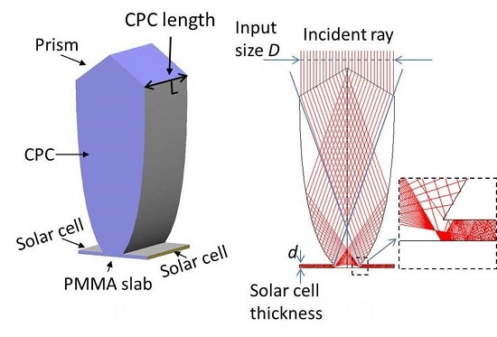
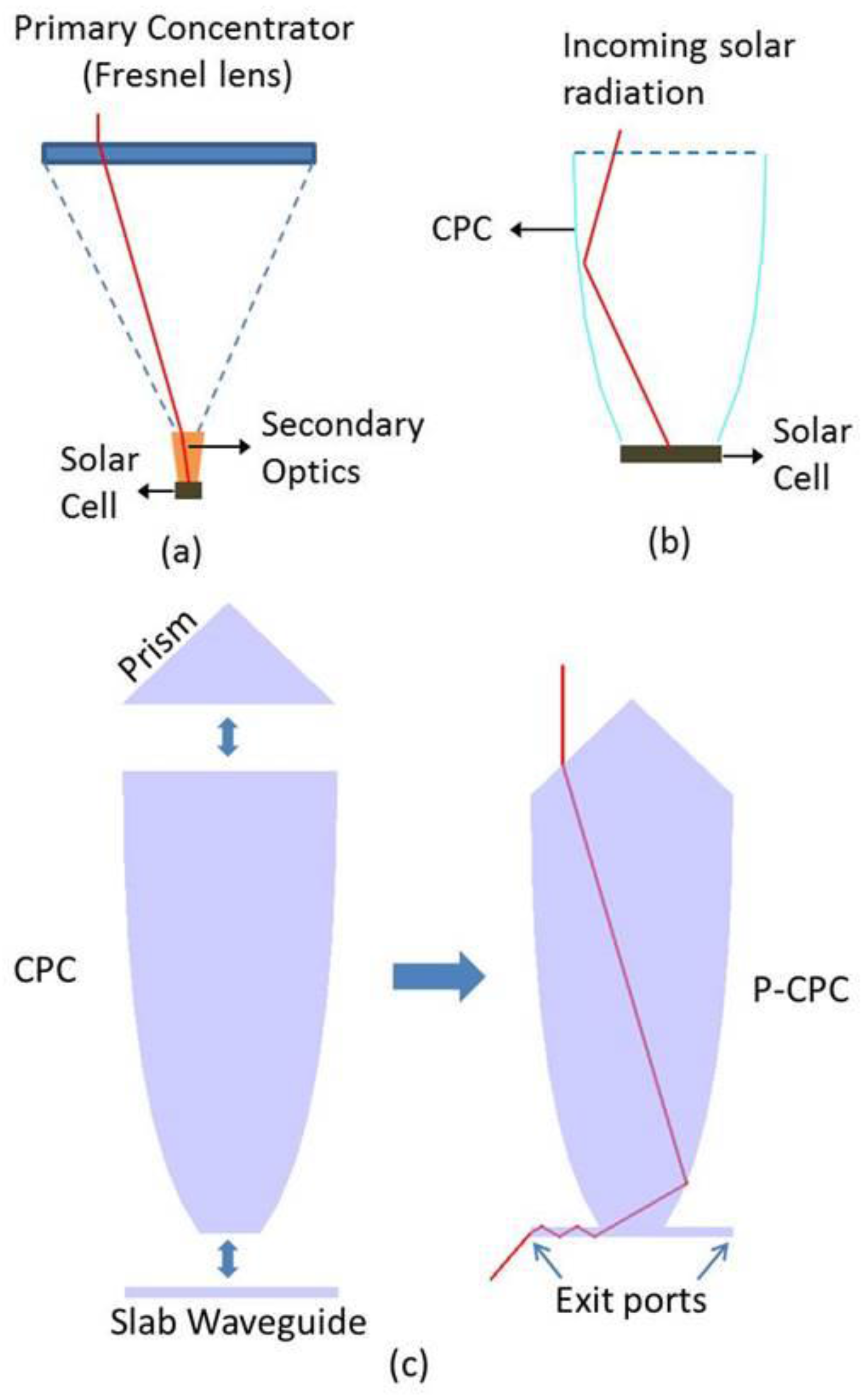
2. Proposed Sunlight Concentrator of CPV System

In this section, we introduce the conceptual design and working principle of the combination of prism-CPC. The idea is based on a CPC that has been used for many different applications, ranging from high-energy physics to solar energy collection. To modify CPCs for our purpose, we recall the theory of conventional CPCs. A symmetrical CPC consists of two identical parabolic reflectors that funnel radiation from the aperture to the absorber [12]. The right-hand side and the left-hand side parabolas are axisymmetric. The focuses of the two parabolas that form the base of the CPC are shown in Figure 2a. When a sunlight beam is parallel to the main axis of the parabolic rim, it will be concentrated on the focus of the parabola, as illustrated in Figure 2b. A solid dielectric CPC is filled with dielectric materials, such as poly-methyl methacrylate (PMMA) [13]. When the incidence angles of the incoming rays are smaller than the acceptance angle, the rays would undergo total internal reflection or mirror reflection to reach the base of the CPC [14].
In this study, we propose a new way of using a solid dielectric CPC that utilizes the imaging optics properties of a CPC which is a non-imaging optics device. Figure 3 shows the physical layout of our proposed solar concentration device based on a P-CPC combination. The prism is placed at the top of a CPC and can change the direction of an incoming solar ray. A PMMA slab is attached to the base of the CPC, and multi-junction solar cells are placed on two edges of the slab. With the appropriate prism angle, the direct sunlight is refracted at two sides of the prism and is divided into two separate beams that are parallel to the axes of the two parabolic rims of the CPC. After reflection at the wall of the CPC, two beams are focused at the focal points of the parabola, as shown in Figure 3b. The light propagates by reflection inside the slab waveguide to reach the solar cell on the edge.
Figure 4 shows the method to calculate the structure of the prism based on the acceptance angle of the CPC. The incident angle θi of the sunlight ray at the edge of the prism is equal to angle α of the prism (θi = α). The refracted ray should be in the direction of the parabolic rim axis of the CPC (acceptance angle of CPC: θacc). Based on Snell’s law, the relationship between θi and θacc is shown in Equation (1):
sin θ i = n P sin ( θ i θ a c c )
where nP is the refractive index of the prism. Solving Equation (1), we can find the structure of the prism. For this CPV system, the effective sunlight collecting area is calculated by the product of CPC length and input size D (the input size D is indicated in Figure 3b). The output apertures are two edges of the slab waveguide whose area is the multiplication of the length of the CPC by thickness d (parameter d is also indicated in Figure 3b). Therefore, the geometric concentration ratio of the system, CR, is the input size D divided by two times the waveguide thickness, as shown in Equation (2).
C R =   C P C   l e n g t h   2 × w a v e g u i d e   t h i c k n e s s = D 2 d
The design of the CPV system powered by renewable solar energy was presented in this section. The sunlight concentrator researched in this study is composed of a prism, a CPC, and a slab waveguide. The concentrator is supposed to be equipped with a tracking system to collect sunlight in the normal direction [15]. Two solar cell strings are attached at the output apertures of the optical concentrator to absorb sunlight and to convert the sunlight into electrical energy. The components of the optical system, the design parameters, and their effects on the optical performance are discussed in more detail in the following section.

3. Optical Analysis and Performance

Optical modelling plays a crucial role in the efficiency evaluation of an optical system. The commercial optical modeling software LightTools™ (Synopsys Inc., San Frrancisco, CA, USA) was used to design and simulate the geometrical structure of the P-CPC solar concentration system [16]. In the designed system, one of the most common optical plastics, poly-methyl methacrylate (PMMA) with a refractive index of nPMMA = 1.49, was selected for the prism, CPC, and slab waveguide. To evaluate the losses in the system, we inserted three luminous flux receivers in the simulation model, as shown in Figure 5.
The optical efficiency, which is simply defined as the ratio of the output luminous flux to the input luminous flux, is a function of the reflection and absorption losses.
η = F l u x   o n   R e c e i v e r   2 + F l u x   o n   R e c e i v e r   3 F l u x   o n   R e c e i v e r   1
The efficiency of the system depends on the shape of the CPC and the system concentration ratio. These problems are discussed in detail in Section 3.1 and Section 3.2.

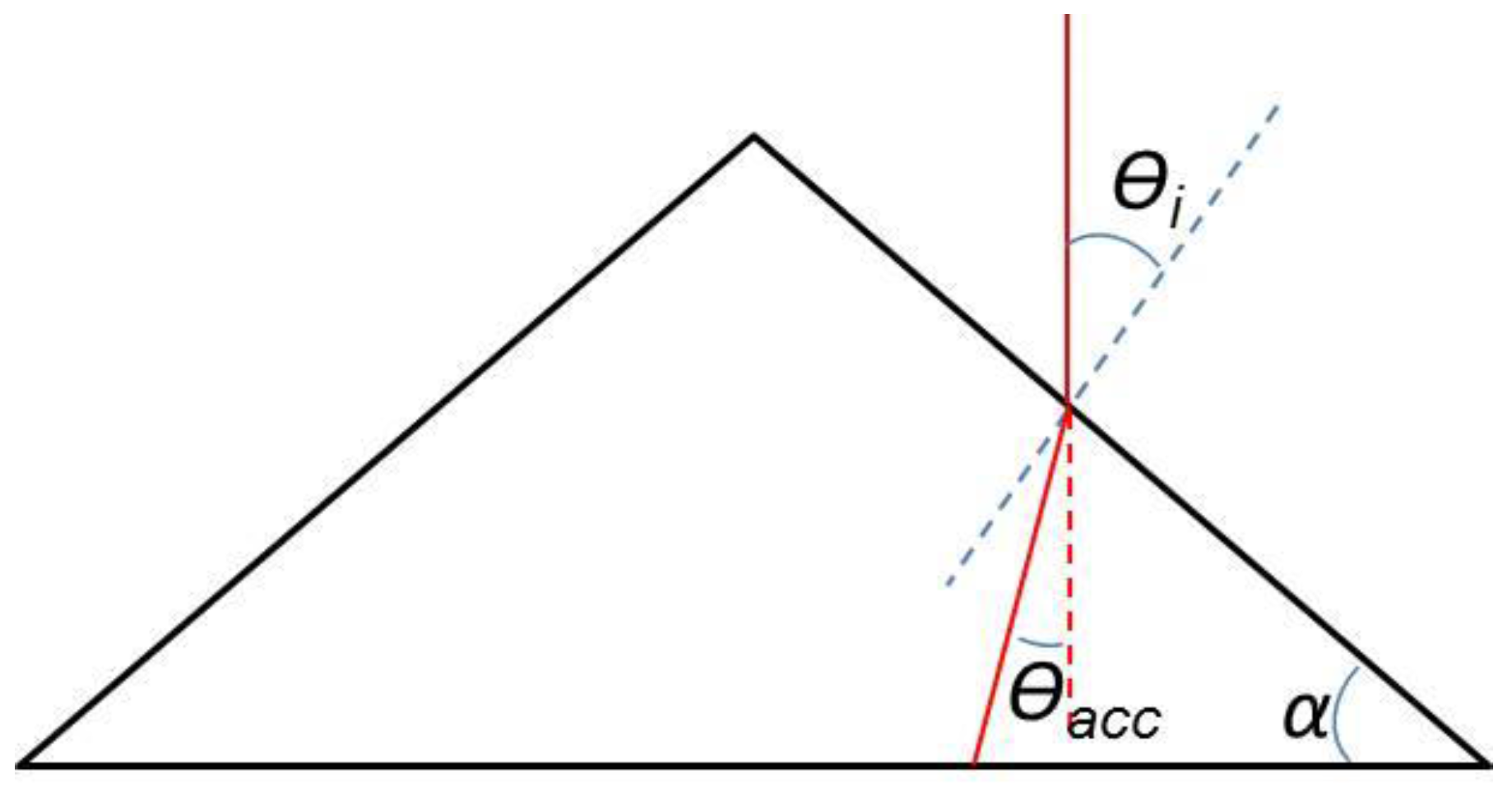
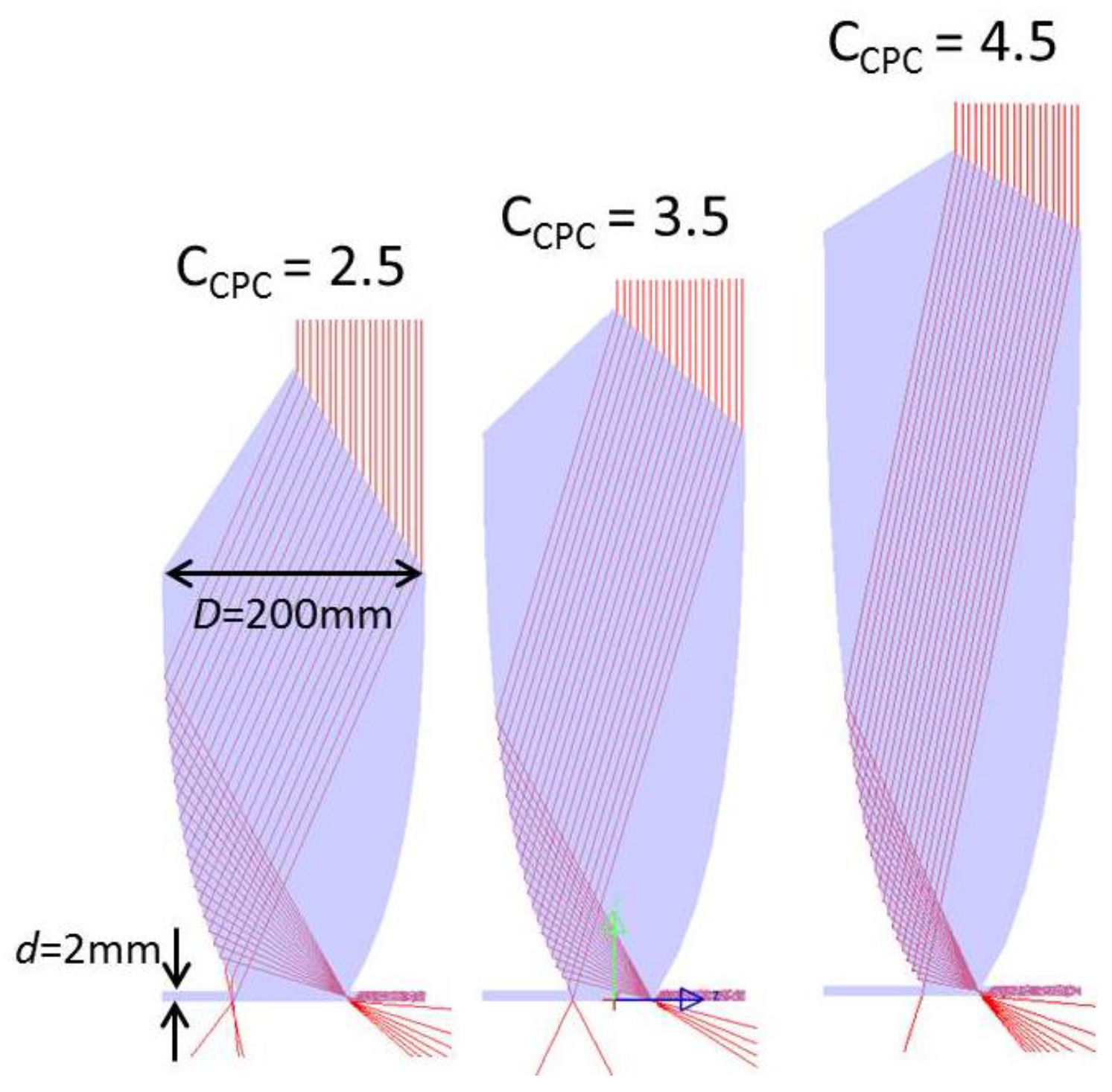
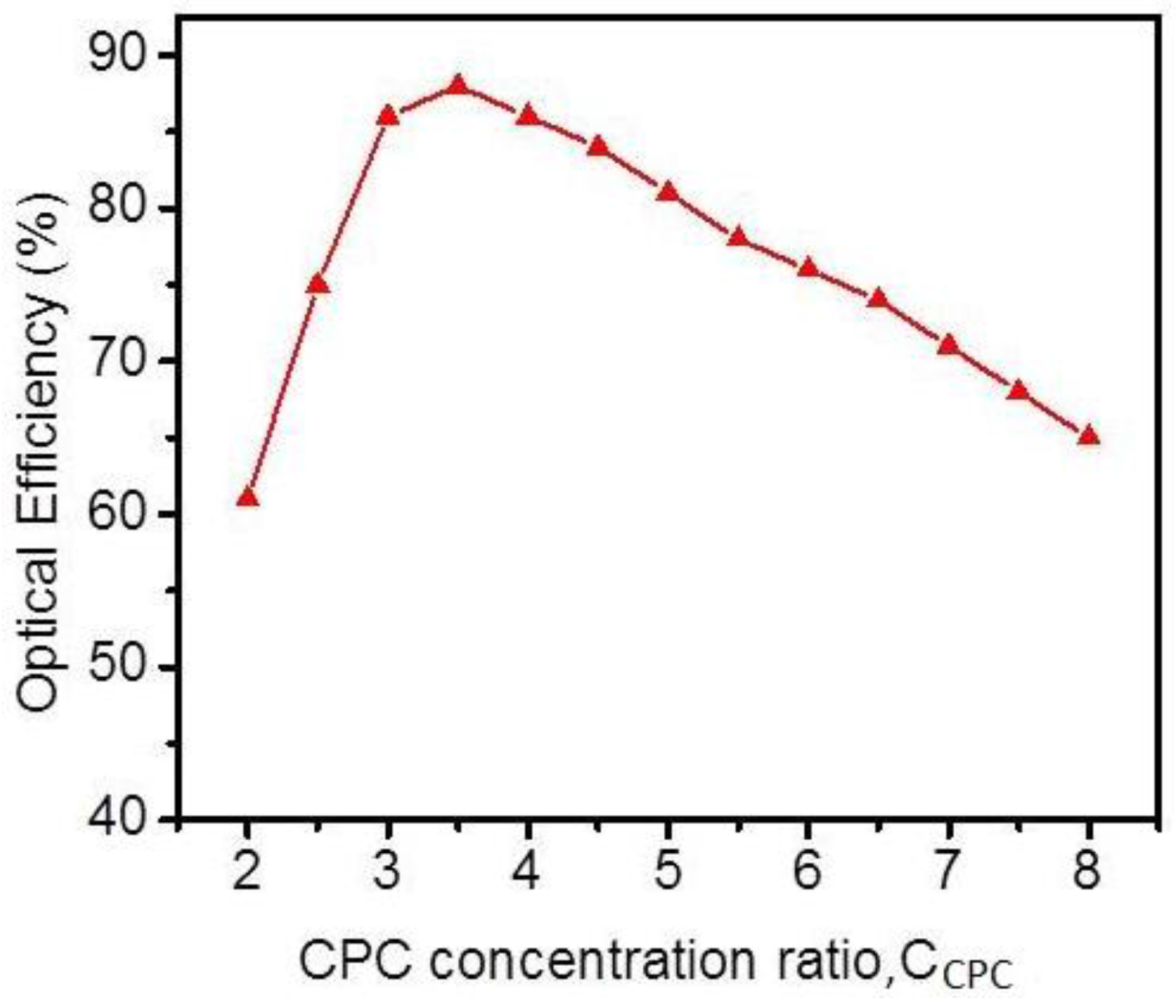
3.1. Optimization of the Shape of the CPC

The loss mechanism is illustrated by ray tracing, as shown in Figure 6. The Fresnel reflection losses occur at the boundaries where the light passes from one region to another with different refractive indices. In this proposed system, the Fresnel losses occur at the surface of the prism. Other Fresnel loss at the conjunction between the solar cells and the edges of the waveguide can be reduced to below 0.1% by filling the gap with the index-matching gel, and then it can be ignored in comparison with other losses. The leak at the parabolic wall of the CPC and the bottom surface of the slab waveguide are also important and can significantly affect the final efficiency of the system. These kinds of losses are caused by some rays that cannot satisfy the total internal reflection (TIR) condition inside the P-CPC concentrator. These losses depend on the shape of the CPC and can be prevented when the solid CPC and slab waveguide have a mirror coating. However, the mirror coating usually has a lower reflectance than the total internal reflection, so the coating can have a positive or a negative effect on the optical performance of a P-CPC. Applying a mirror coating process also makes the system more costly.
In order to quantify the effect of CPC shape on the efficiency of the system, a parametric analysis was carried out whilst varying its CPC concentration ratio, CCPC. The CCPC is defined by the ratio between the input aperture size and the output aperture size of the CPC. The changing of the CCPC does not affect the geometric concentration ratio of the system, CR which was defined by Equation (2). We fixed the input aperture of the CPC (input size of system) to D = 200 mm. The thickness of the slab waveguide is d = 2 mm. Based on Equation (2), the concentration ratio of the system achieves CR = 50. Based on this, the geometry model of the sample CPC was created in LightTools™ for ray tracing analysis. The LightTools™ software was also used to study the behavior of rays within the P-CPC for different CPC structures. A total of 1000 rays were traced [4]. The ray-tracing analysis was conducted for a few different CPC structures. Figure 7 shows the variation of the P-CPC concentration system with different CCPC.
It is clear from Figure 7 that as the CCPC increases, the incident angle of sunlight at the surface of the prism decreases, so Fresnel loss also decreases. The leak at the parabolic rim and the slab waveguide also change with different CCPCs. In order to optimize the structure of P-CPC for maximum efficiency, we carried out a simulation with several different CPC concentration ratio CCPC ranging from 2 to 8 in 0.5 increments. Figure 8 shows the variation of optical efficiencies at different CCPC concentration ratios for the CPC. The simulation for optical efficiency of a sunlight concentrator based on a P-CPC was implemented. In the implementation we included material attenuation, Fresnel reflection losses, and geometrical losses (the leak at the parabolic wall of the CPC and the bottom surface of the slab waveguide). Figure 8 shows that CCPC = 3.5 is the optimal value for the CPC to obtain the highest efficiency of 89%.

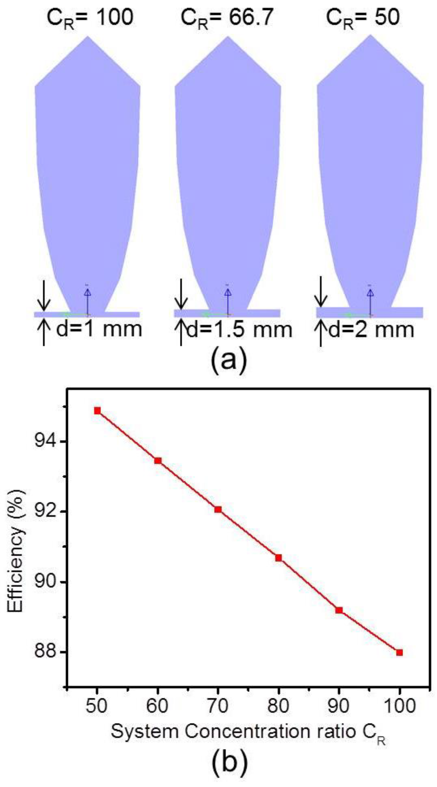
3.2. The Dependence of Efficiency on the System Concentration Ratio CR

The prism attached at the top of the CPC to direct the sunlight beam is shown in Figure 3. However, the prism has an inherent disadvantage, which is the dispersion of the solar spectrum. For CPV systems, the dispersion of the solar spectrum range is very important because it leads to an essential decrease in the optical efficiency and concentration ratio of the systems. Figure 9 illustrates schematically how the sunlight beam passes through a P-CPC via a dispersion mechanism. The sunlight is dispersed at the focal point of the P-CPC due to the wavelength dependence of the refractive index of the prism material. The focused area also defines how big the sun’s image will be at the focal point, and it affects the coupling between the CPC and the slab waveguide. Larger slab waveguide thickness will capture more focused sunlight but will decrease the concentration ratio of the system.
We used ray tracing in LightTools™ to analyze the dependence of efficiency on the thickness of the slab waveguide that is governed by the dispersion phenomenon. The sunlight source used in the analysis, generated by LightTools™, was in the range of 250–2500 nm [17]. The input aperture size is fixed at D = 200 mm, and the thickness of the slab waveguide d varies from 1 mm to 2 mm in the step of 0.2 mm. This means the concentration ratio CR decreases from 100 to 50 in the step of 10. Figure 10a illustrates the P-CPC structures with some different slab waveguide thicknesses, d = 1 mm, 1.5 mm, and 2 mm, respectively. Figure 10b shows the simulated optical efficiency at different system concentration ratios. It can be seen that because of dispersion, system efficiency η decreases almost linearly with the increase of CR. The lower concentration ratio can provide higher optical efficiency, but it also increases the area requirement of solar cells.

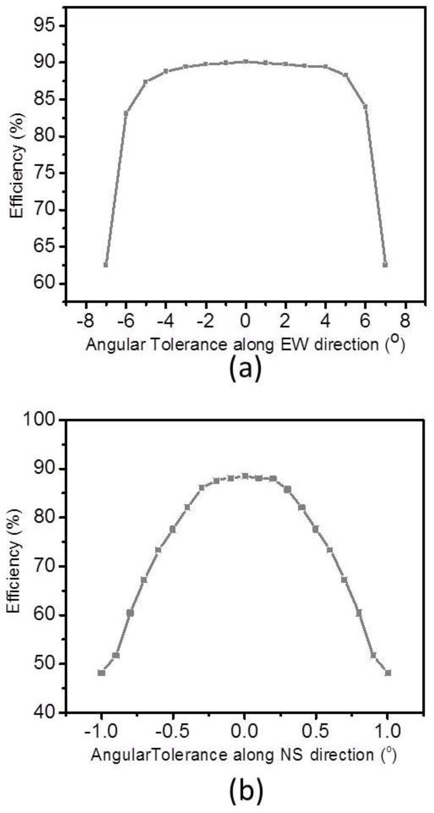
3.3. Tolerance of the System

For proper operation of the proposed solar concentration system, direct sunlight should always be parallel to the main axis of the P-CPC. This is a difficult task because the position of the sun is always changing, and this led us to use a sun tracking system. The required accuracy of the sun tracking system is determined by the solar concentrating collector’s angle of tolerance [18,19,20,21]. The tolerance of the system is the acceptable angular deviation of the sunlight direction from the two main axes of the system within the allowable efficiency loss. It is defined as the angle where the efficiency drops by 10% [22]. The acceptance angle determines the required accuracy of the tracking system mounted on the concentrator. The dependence of the optical efficiency of the system on angular deviation along the north-south (NS) and east-west (EW) direction is very different because the system is not symmetric. We examined the efficiency with different angular deviations of the sunlight direction along the NS and EW directions. The alignment of the system along the NS and EW directions is shown in Figure 11.
Figure 12a shows the optical efficiency output relative to the angular deviation along the EW direction, and Figure 12b shows a graph of efficiency versus angular deviation along the NS direction. The simulation results show that the tolerance is more than ±6° along the EW direction, which is far larger than that for the EW direction (±0.5°). This indicates that, by using a P-CPC, the acceptance angle along the EW direction can be greatly increased without sacrificing optical efficiency too much. Therefore, unlike the conventional lens or parabolic mirror system for concentrators, the proposed P-CPC system can lower the accuracy requirements along the EW direction, and this reduces the cost of the tracking system. As the size of the slab waveguide becomes larger, the focused light from the primary CPC can be transferred more effectively to the waveguide without being decoupled. A volumetric increase of the slab waveguide while keeping the input aperture the same gives better tracking tolerance along the NS direction. However, increasing the acceptance angle reduces the concentration ratio dramatically. Therefore, the tolerance and the concentration ratio should be kept in balance in the system design.

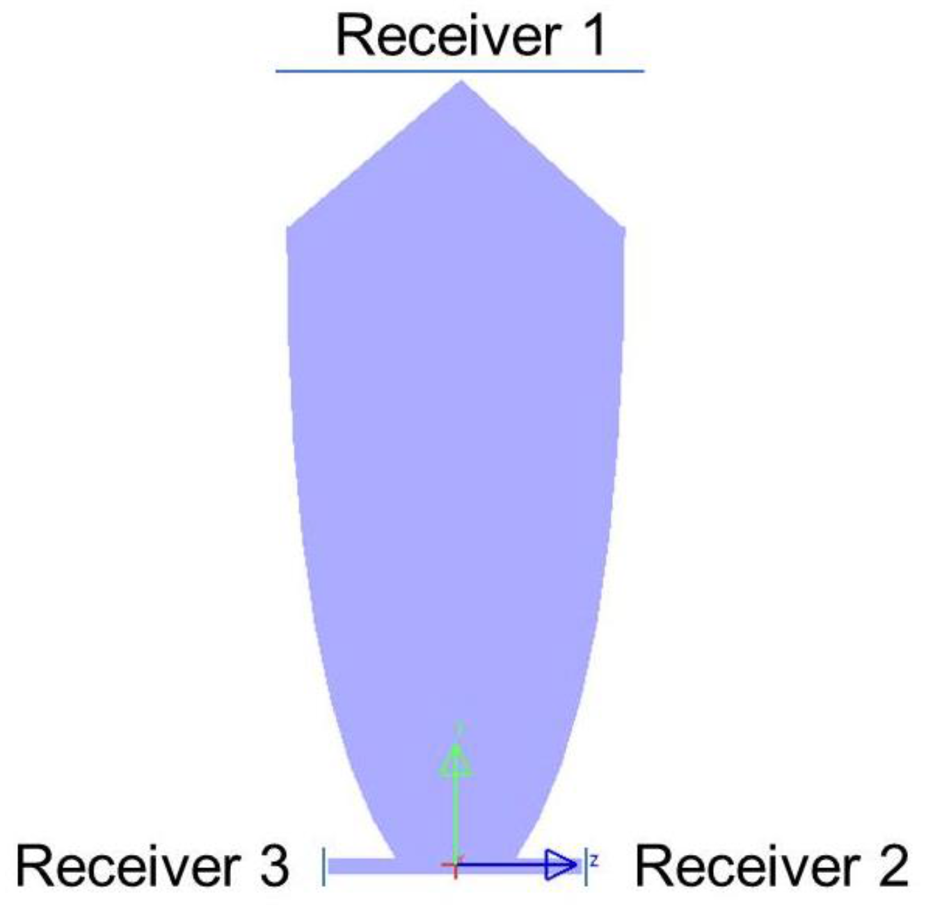
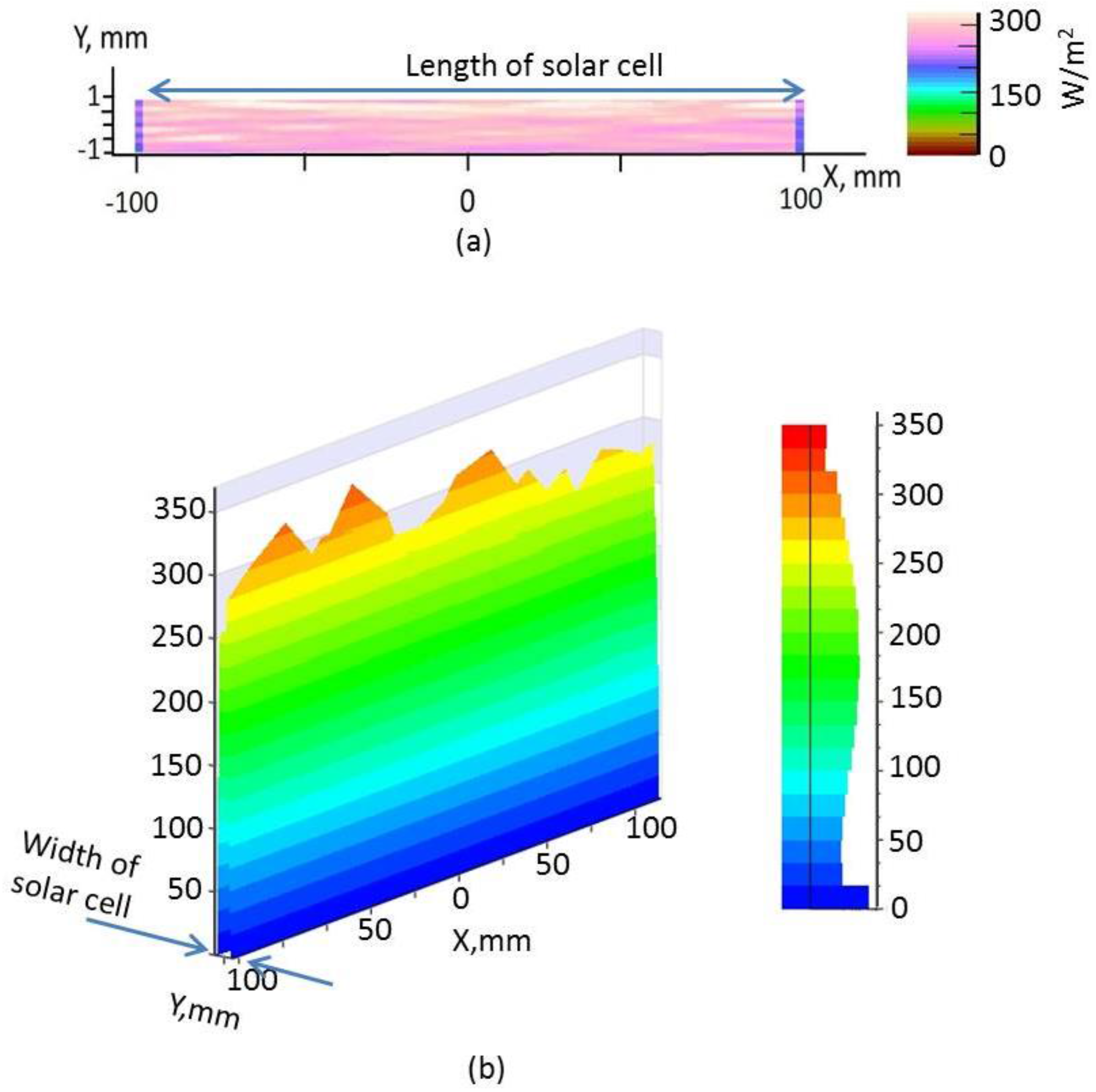
3.4. Irradiance Distribution on the Surface of the Solar Cell

Besides concentration and the tolerance angle, an optical PV concentrator must achieve other goals [7]. One of these is irradiance uniformity on the cell. This is important not only because the cell efficiency depends on it but also to assure long-term cell and concentrator reliability. High flux contrast across the cell surface causes serious resistance losses, although this is less dramatic in multi-junction solar cells than in silicon cells. Another limitation specific to multi-junction cells, however, comes from tunnel diodes that need to be operating in their tunneling regime. This limits the irradiance at any point of the cell. Additionally, if different wavelengths have a different irradiance distribution (which has been referred to as the chromatic aberration of irradiance), the cell efficiency can be significantly affected due to a local current mismatch between the top and middle junctions. In this proposed solar concentrator, the slab waveguide works as a homogenizer for attaining good irradiance uniformity on the solar cells. With a slab waveguide homogenizer, the solar cell is glued to two edges; most of the light reaches the cell after bouncing off the waveguide surfaces by TIR [23,24,25]. The light distribution on the cell can be made uniform after sufficient length of slab waveguide. The uniformity of irradiation on the surface of the solar cell was evaluated and simulated using the same optical software (LightTools™). There are two solar cells which are attached at two exit ports of P-CPC, but they have the same uniformity because of symmetry property of P-CPC. We analyzed the uniformity at only one exit port. Figure 13a,b shows 2D and 3D irradiance distribution graph on the exit port. The maximum irradiance was 330 W/m2, the minimum irradiation was 285 W/m2, and the average irradiance was 299 W/m2. A uniformity Equation (4) [26] was adopted to calculate the uniformity of P-CPC concentrator, which reached 92.5%. It is clear that the proposed P-CPC can provide excellent irradiance uniformity on the cell.
U n i f o r m i t y = ( 1 M a x i m u m   I r r a d i a t i o n M i n i m u m   I r r a d i a t i o n 2   × A v e r a g e   i r r a d i a t i o n   ) × 100 %

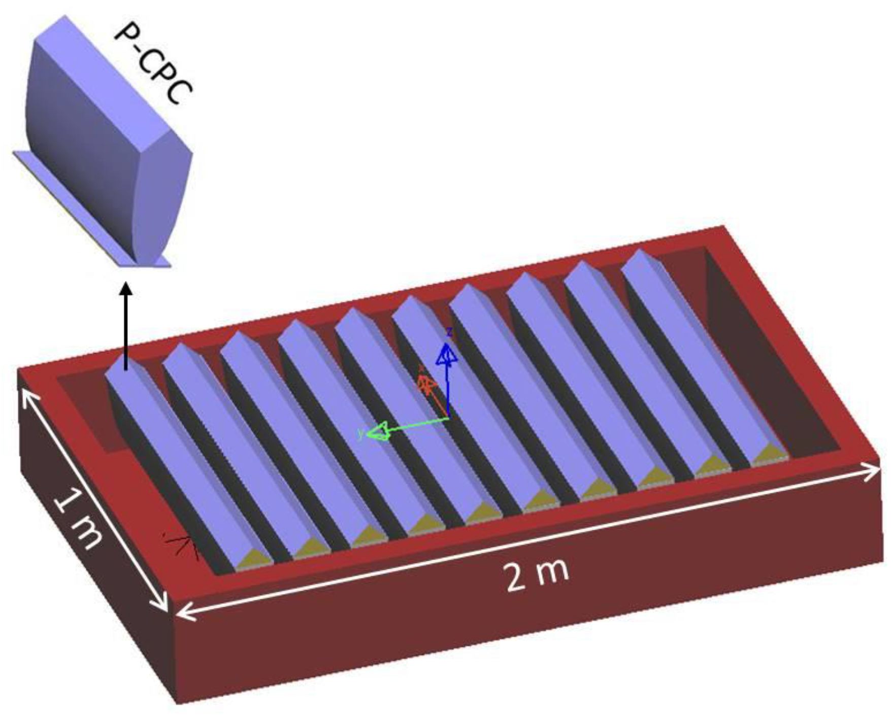
3.5. Proposed Large-Scale System and Discussion

As an initiative for a cost-effective large-scale solar concentration system, 10 P-CPCs are placed together. These systems share a sun tracking system, a battery bank, and other infrastructure. The system will include a linear array of P-CPCs. A schematic description of a sunlight collector for a large-scale CPV system is shown in Figure 14. The concentration ratio of this system is flexible, depending on the thickness of the waveguide. For different concentration ratios, different solar cells can be used. For high concentration systems of CR = 50 proposed in this study, III–V multi-junction solar cells are suggested. Multi-junction solar cells made of III–V compound semiconductors can have efficiencies of more than 40%. Although they are expensive, the smaller size solar cells for higher concentration ratios would make the system more cost-effective.
To evaluate the performance of the large scale CPV system, the irradiation from the sunlight was calculated at different times of day by LightTools™. The simulation considers the direct normal irradiance solar spectrum, generated by LightTools™, as the incident irradiance input parameter. Here, let us look at the solar irradiation for a summer day as an example. The highest solar elevation (zenith) angle at the site is 76°, and it takes place at 12:30 p.m. [27]. To achieve direct sunlight, we assume that the CPV system is mounted with a sun tracking device to rotate concentrator module toward the sun all time of the day. The area of the sunlight collector is 2 m2 as shown in Figure 14. Figure 15 shows the power of sunlight at the collecting surface of CPV system and output power at different times. The total output energy per day can be calculated by integration of output power over time. Based on Figure 15, the total solar energy along a day at the output is 18 KWh. Using multi-junction solar cells made of III–V compound semiconductors which have efficiencies of more than 40%, the system can generate about 7.2 KWh of electricity per day.
The P–CPC concept introduced here fulfills the requirements for a concentrator of a CPV system, such as a high concentration ratio and a highly uniform distribution of radiance on the surface of solar cells. Reducing the use of materials will also contribute to reduced manufacturing costs, reduced supplier management costs, and reduced recycling costs. To achieve low fabrication costs, it is necessary to have one component, one material, and one manufacturing process for the concentrator design. The P-CPC concept proposed here meets all these requirements. It is made of a single component and a single material, and it uses a single manufacturing process, such as injection molding and/or extrusion, which is suitable for mass production. These features have resulted in reduced manufacturing costs [28].

4. Conclusions

A CPV system using P-CPCs has been designed and discussed. To explore the practical performance of the proposed system, a sample optical system was modeled and simulated with LightTools™. The simulation results indicate that 89% optical efficiency was achieved at Cgeo = 50 for the proposed concentrator system. In addition, the angular tolerance (acceptance angles) in the NS and the EW directions was also analyzed. By using a P-CPC, an acceptance angle of ±6° was achieved in the EW direction. This allows us to use a less accurate sun tracking system, such as a seasonal sun tracking system along the EW direction, as a cost-effective solution. This study is the first to use a combination of a prism and a CPC for a solar concentration system. The proposed system is very suitable for large-scale purposes. It shows great potential for commercial- and industrial-scale CPV applications. In the future, we will try to implement experimentation under real conditions to verify the accuracy of the simulation and the commercial viability of the system.

Acknowledgments

This work was supported by the National Research Foundation of Korea (NRF) grant funded by the Korean government (MSIP) (No. 2014R1A2A1A11051888).

Author Contributions

Ngoc Hai Vu and Seoyong Shin conceived and developed the original ideas. Ngoc Hai Vu carried out the performance analysis and simulations and wrote the paper. Seoyong Shin supervised the research and finalized the paper.

Conflicts of Interest

The authors declare no conflict of interest.

References

  1. Baig, H.; Sellami, N.; Mallick, T.K. Trapping Light Escaping from the Edges of the Optical Element in a Concentrating Photovoltaic System. Energy Convers. Manag. 2015, 90, 238–246. [Google Scholar] [CrossRef]
  2. Rumyantsev, V.D.; Ashcheulov, Y.V.; Davidyuk, N.Y.; Ionova, E.A.; Pokrovskiy, P.V.; Sadchikov, N.A.; Andreev, V.M. CPV Modules Based on Lens Panels. Adv. Sci. Technol. 2010, 74, 211–218. [Google Scholar] [CrossRef]
  3. Rumyantsev, V.D. Solar concentrator modules with silicone-onglass Fresnel lens panels and multijunction cells. Opt. Express 2010, 18, A17–A24. [Google Scholar] [CrossRef] [PubMed]
  4. Pei, G.; Li, G.; Su, Y.; Ji, J.; Riffat, S.; Zheng, H. Preliminary ray tracing and experimental study on the effect of mirror coating on the optical efficiency of a solid dielectric compound parabolic concentrator. Energies 2012, 5, 3627–3639. [Google Scholar] [CrossRef]
  5. Antonini, A.; Stefancich, M.; Coventry, J.; Parretta, A. Modelling of Compound Parabolic Concentrators for Photovoltaic Applications. Int. J. Opt. Appl. 2013, 3, 40–52. [Google Scholar] [CrossRef]
  6. Jing, L.; Liu, H.; Wang, Y.; Xu, W.; Zhang, H.; Lu, Z. Design and optimization of fresnel lens for high concentration photovoltaic system. Int. J. Photoenergy 2014, 2014, 1–7. [Google Scholar] [CrossRef]
  7. Benítez, P.; Miñano, J.C.; Zamora, P.; Mohedano, R.; Cvetkovic, A.; Buljan, M.; Chaves, J.; Hernández, M. High performance Fresnel-based photovoltaic concentrator. Opt. Express 2010, 18, A25–A40. [Google Scholar] [CrossRef] [PubMed]
  8. Winston, R. Principles of Solar Concentrators of a Novel Design. Sol. Energy 1974, 16, 89–95. [Google Scholar] [CrossRef]
  9. Parretta, A.; Antonini, A. Optics of Solar Concentrators. Part II: Models of Light Collection of 3D-CPCs under Direct and Collimated Beams. Int. J. Opt. Appl. 2013, 3, 72–102. [Google Scholar]
  10. Winston, R. Dielectric compound parabolic concentrators. Appl. Opt. 1976, 15, 291–292. [Google Scholar] [CrossRef] [PubMed]
  11. Mallick, T.K.; Eames, P.C.; Norton, B. Non-concentrating and asymmetric compound parabolic concentrating building facade integrated photovoltaics: An experimental comparison. Sol. Energy 2006, 80, 834–849. [Google Scholar] [CrossRef]
  12. Rabl, A. Comparison of solar concentrators. Sol. Energy 1976, 18, 93–111. [Google Scholar] [CrossRef]
  13. Goodman, N.B.; Ignatius, R.; Wharton, L.; Winston, R. Solid-dielectric compound parabolic concentrators: On their use with photovoltaic devices. Appl. Opt. 1976, 15, 2434–2436. [Google Scholar] [CrossRef] [PubMed]
  14. Winston, R.; Zhang, W. Pushing concentration of stationary solar concentrators to the limit. Opt. Express 2010, 18, A64–A72. [Google Scholar] [CrossRef] [PubMed]
  15. Tsuei, C.-H.; Sun, W.-S.; Kuo, C.-C. Hybrid sunlight/LED illumination and renewable solar energy saving concepts for indoor lighting. Opt. Express 2010, 18, A640–A653. [Google Scholar] [CrossRef] [PubMed]
  16. Gajic, M.; Karwa, M.; Mojiri, A.; Rosengarten, G. Modeling reflection loss from an evacuated tube inside a compound parabolic concentrator with a cylindrical receiver. Opt. Express 2015, 23, A493–A501. [Google Scholar] [CrossRef] [PubMed]
  17. Gueymard, C.A.; Myers, D.; Emery, K. Proposed reference irradiance spectra for solar energy systems testing. Sol. Energy 2002, 73, 443–467. [Google Scholar] [CrossRef]
  18. Lee, C.; Chou, P.; Chiang, C.; Lin, C. Sun tracking systems: A review. Sensors 2009, 9, 3875–3890. [Google Scholar] [CrossRef] [PubMed]
  19. Khan, M.T.A.; Tanzil, S.M.S.; Rahman, R.; Alam, S.M.S. Design and construction of an automatic solar tracking system. In Proceedings of the 2010 International Conference on Electrical and Computer Engineering (ICECE), Dhaka, Bangladesh, 18–20 December 2010; pp. 326–329.
  20. Song, J.; Zhu, Y.; Jin, Z.; Yang, Y. Daylighting system via fibers based on two-stage sun-tracking model. Sol. Energy 2014, 108, 331–339. [Google Scholar] [CrossRef]
  21. Mousazadeh, H.; Keyhani, A.; Javadi, A.; Mobli, H.; Abrinia, K.; Sharifi, A. A review of principle and sun-tracking methods for maximizing solar systems output. Renew. Sustain. Energy Rev. 2009, 13, 1800–1818. [Google Scholar] [CrossRef]
  22. Xie, P.; Lin, H.; Liu, Y.; Li, B. Total internal reflection-based planar waveguide solar concentrator with symmetric air prisms as couplers. Opt. Express 2014, 22. [Google Scholar] [CrossRef] [PubMed]
  23. Bouchard, S.; Thibault, S. Planar waveguide concentrator used with a seasonal tracker. Appl. Opt. 2012, 51. [Google Scholar] [CrossRef] [PubMed]
  24. Moore, D.; Schmidt, G.; Unger, B. Concentrated photovoltaics stepped planar light guide. In Proceedings of the International Optical Design Conference 2010, Jackson Hole, WY, USA, 13–17 June 2010; Volume 7652. [CrossRef]
  25. Selimoglu, O.; Turan, R. Exploration of the horizontally staggered light guides for high concentration CPV applications. Opt. Express 2012, 20, 19137–19147. [Google Scholar] [CrossRef] [PubMed]
  26. Shen, S.C.; Chang, S.J.; Yeh, C.Y.; Teng, P.C. Design and testing of a uniformly solar energy TIR-R concentration lenses for HCPV systems. Opt. Express 2013, 21, A942–A952. [Google Scholar] [CrossRef] [PubMed]
  27. Ullah, I.; Shin, S. Highly concentrated optical fiber-based daylighting systems for multi-floor office buildings. Energy Build. 2014, 72, 246–261. [Google Scholar] [CrossRef]
  28. O’Driscoll, M. Design for manufacture. J. Mater. Process. Technol. 2002, 122, 318–321. [Google Scholar] [CrossRef]
Figure 1. Conventional CPV systems using: (a) a Fresnel lens; (b) a CPC; (c) Solar concentrator using a combination of prism-CPC.
Energies 09 00645 g001
Figure 2. (a) A symmetrical CPC; and (b) ray tracing of the sunlight beam that is parallel to the axis of the parabolic rim.
Energies 09 00645 g002
Figure 3. (a) Physical layout of P-CPC; and (b) mechanism of sunlight concentration by ray tracing.
Energies 09 00645 g003
Figure 4. The relationship between the prism structure and the acceptance angle of the CPC.
Energies 09 00645 g004
Figure 5. The simulation structure for optical efficiency analysis.
Energies 09 00645 g005
Figure 6. Loss mechanism of the system.
Energies 09 00645 g006
Figure 7. Schematic diagram of ray-tracing results for the P-CPC concentration system with different shapes of CPCs that have CCPC = 2.5; 3.5 and 4.5.
Energies 09 00645 g007
Figure 8. Variation of optical efficiencies at different CCPC concentration ratios for the CPC.
Energies 09 00645 g008
Figure 9. Mechanism of dispersion inside the P-CPC.
Energies 09 00645 g009
Figure 10. (a) The variation of the P-CPC shape; and (b) the variation of optical efficiency at different system concentration ratios (CR).
Energies 09 00645 g010
Figure 11. The alignment of the system along the NS and EW directions.
Energies 09 00645 g011
Figure 12. Variation of optical efficiency of the concentrator at different angular deviations along the (a) EW direction; and (b) NS direction.
Energies 09 00645 g012
Figure 13. (a) A 2D irradiance distributions on the exit port of P-CPC; and (b) a 3D irradiance distributions on the exit port of P-CPC.
Energies 09 00645 g013
Figure 14. Proposed large-scale CPV system based on P-CPCs.
Energies 09 00645 g014
Figure 15. Power of sunlight at the collecting surface (input power) and output power from solar concentration system at different times of the day.
Energies 09 00645 g015

