
Numerical Prediction of the Mechanical Failure of the Intervertebral Disc under Complex Loading Conditions

 , ,
, ,
Abstract
:
1. Introduction
2. Materials and Methods
3. Results
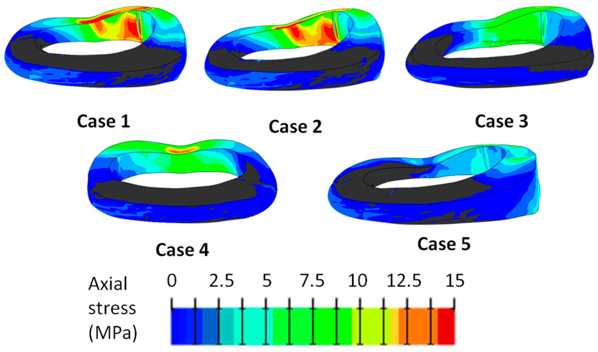
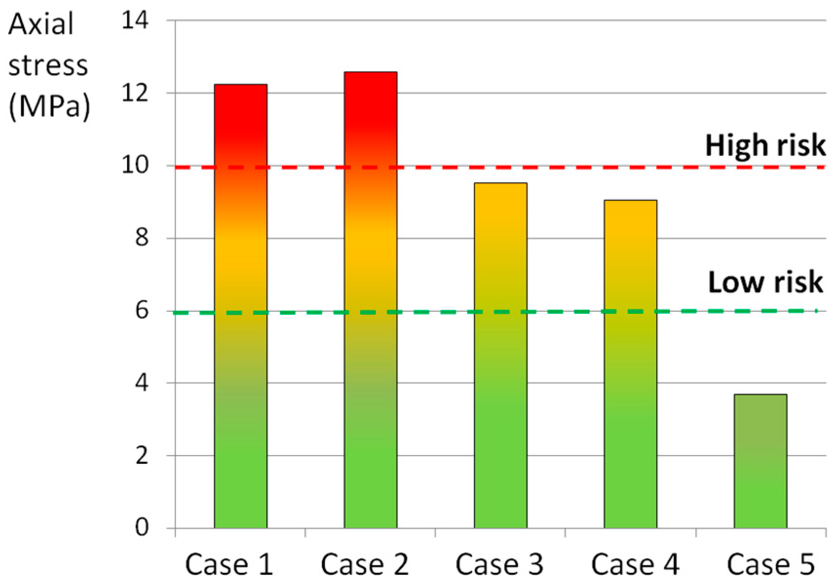
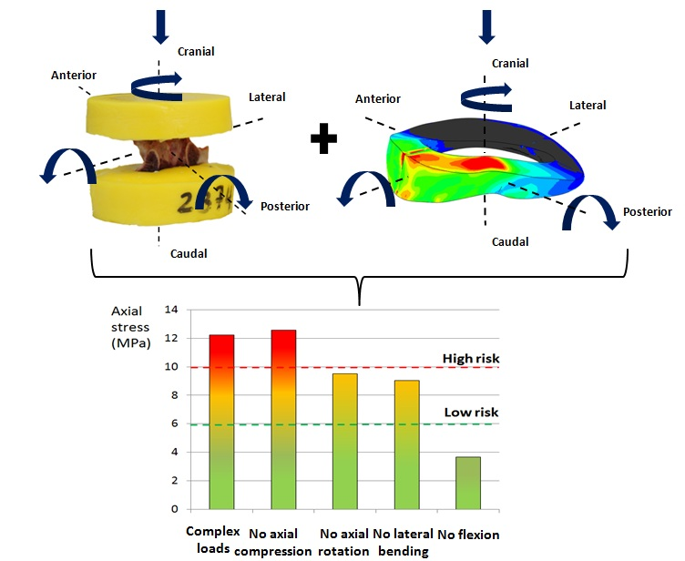
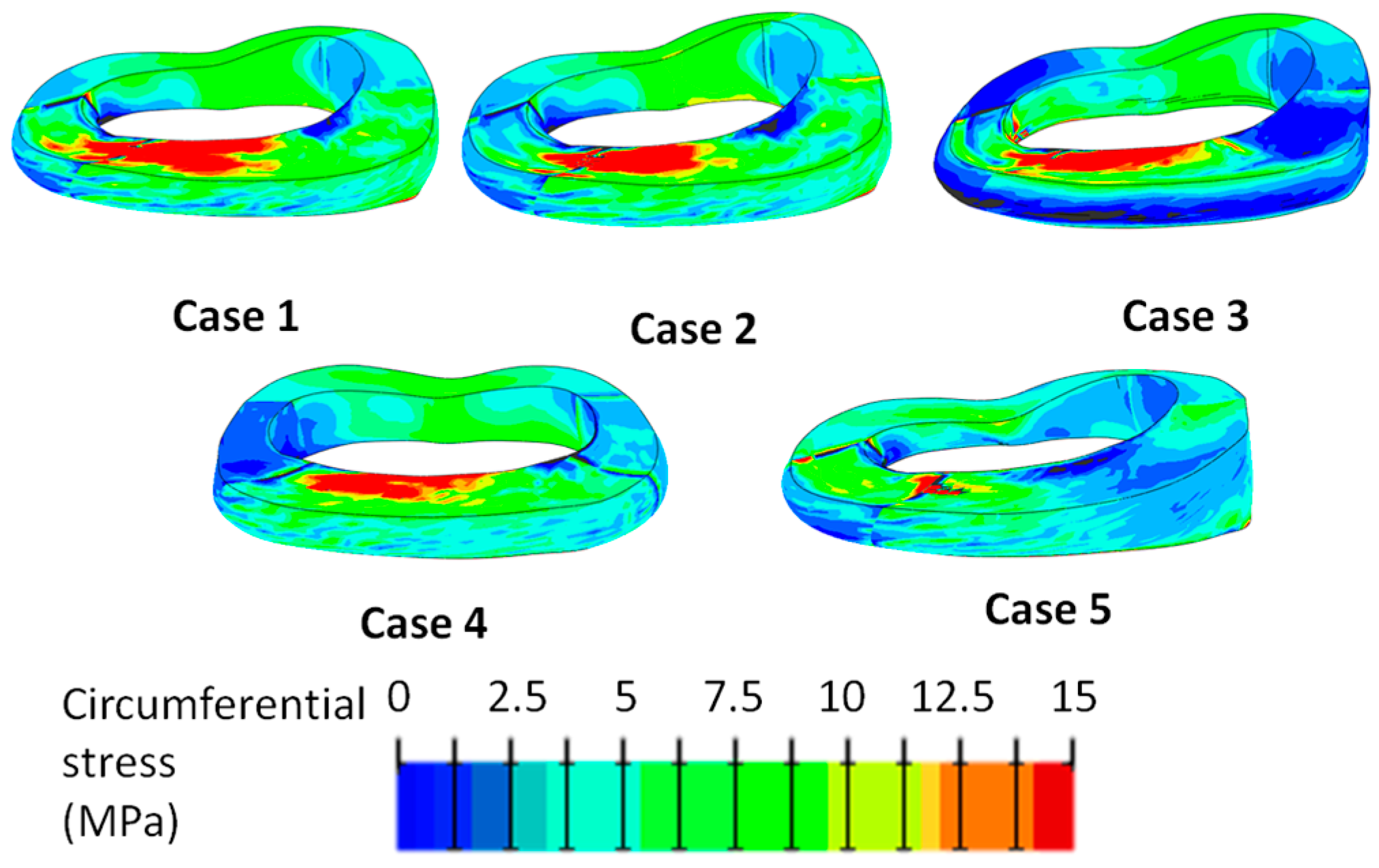
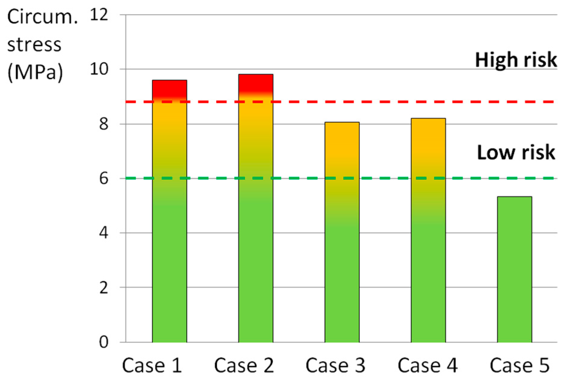
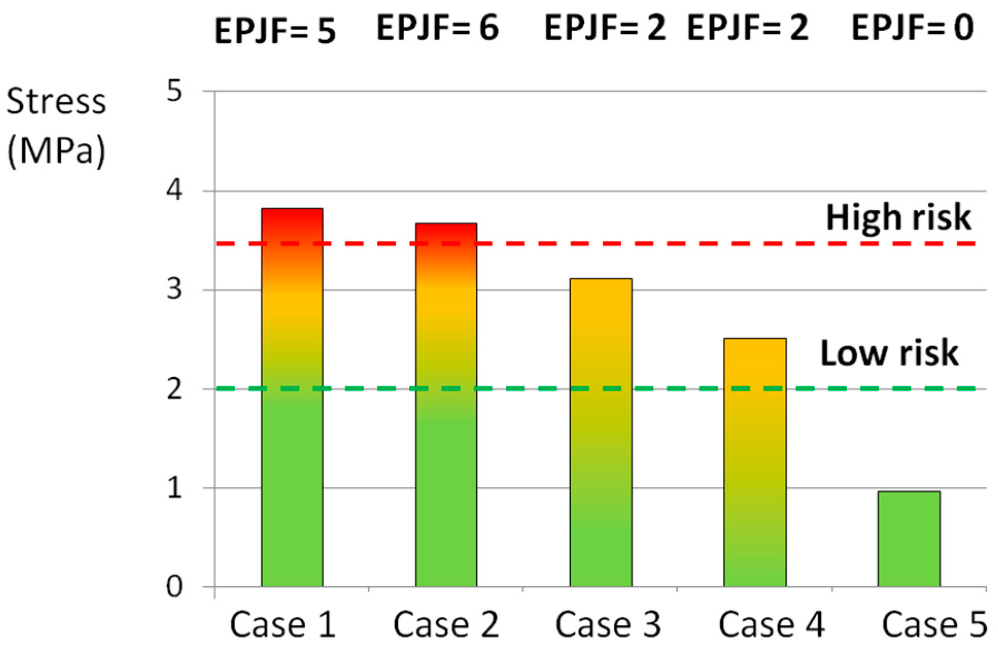
3.1. Complex Loads
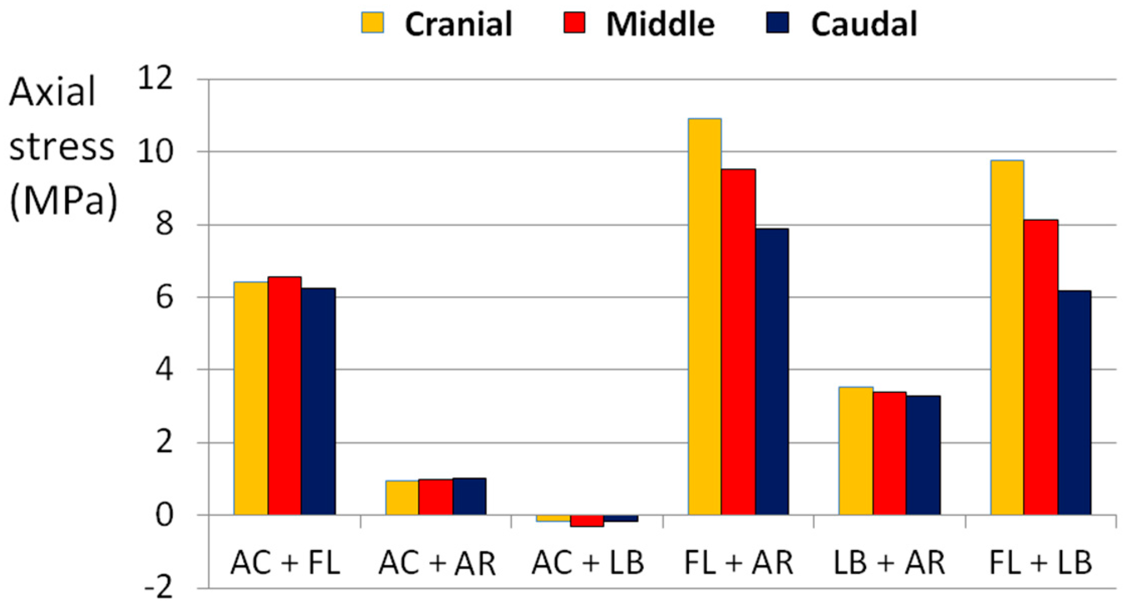
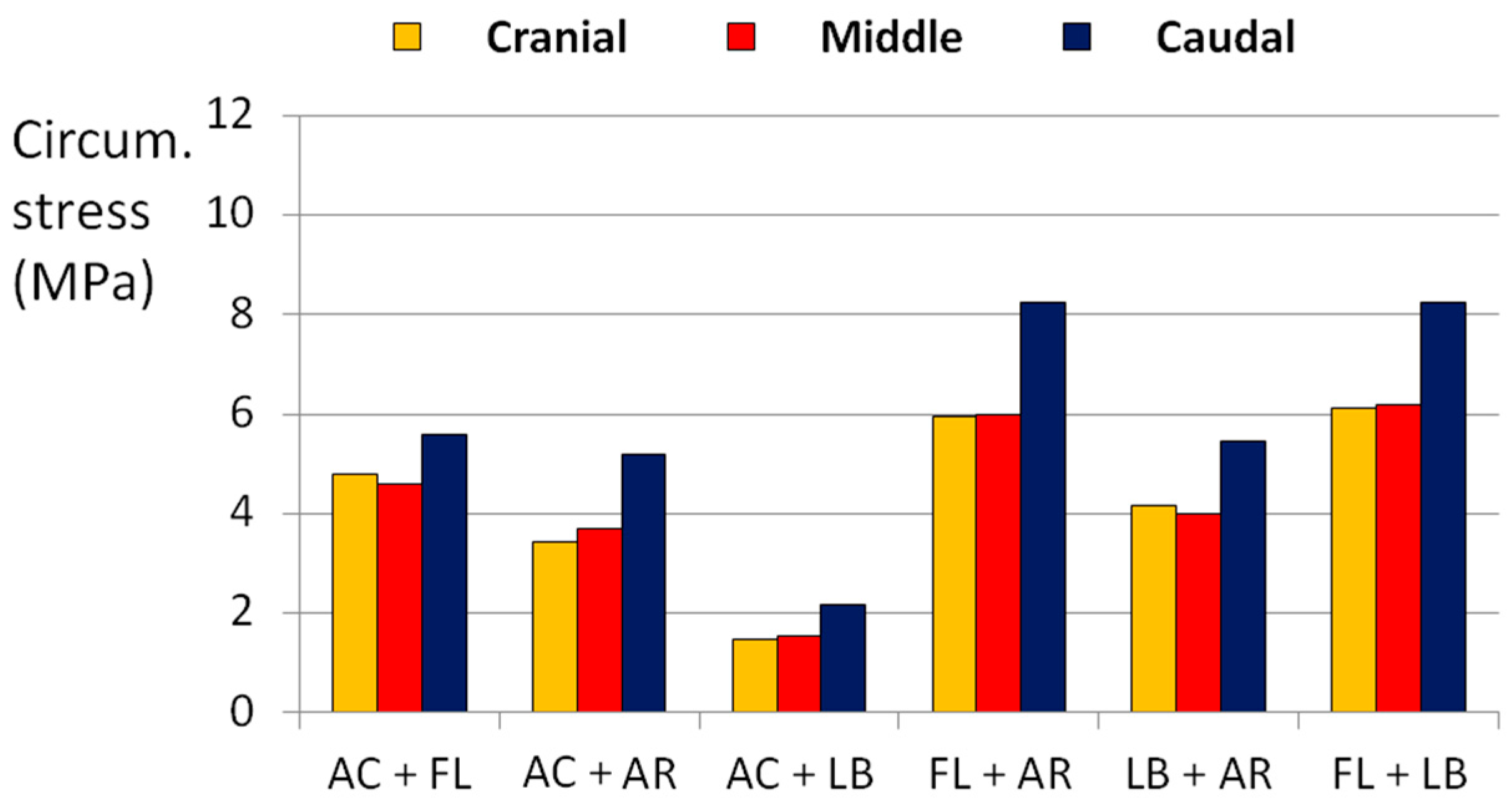
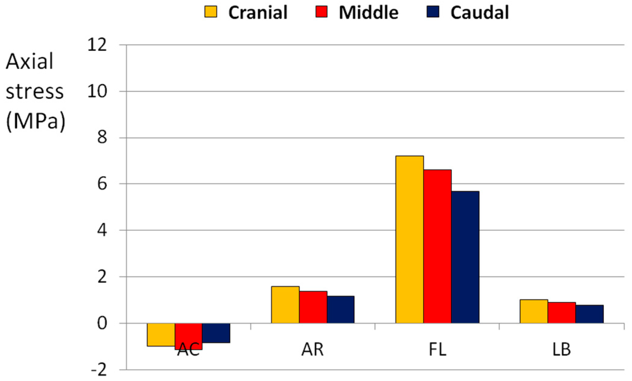
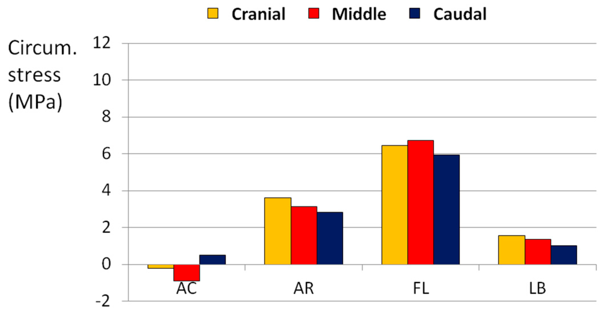
3.2. Simple Loads
4. Discussion
5. Conclusions
Author Contributions
Conflicts of Interest
References
- Virgin, W.J. Experimental investigations into the physical properties of the intervertebral disc. J. Bone Jt. Surg. Br. 1951, 33, 607–611. [Google Scholar]
- Brown, T.; Hansen, R.J.; Yorra, A. Some mechanical tests on the lumbosacral spine with particular reference to the intervertebral discs; a preliminary report. J. Bone Jt. Surg. Am. 1957, 39, 1135–1164. [Google Scholar] [CrossRef]
- Adams, M.A.; Hutton, W.C. The relevance of torsion to the mechanical derangement of the lumbar spine. Spine 1981, 6, 241–248. [Google Scholar] [CrossRef] [PubMed]
- Hansson, T.H.; Keller, T.S.; Spengler, D.M. Mechanical Behavior of the Human Lumbar Spine II. Fatigue Strength During Dynamic Compressive Loading. J. Orthop. Res. 1987, 5, 479–487. [Google Scholar] [CrossRef] [PubMed]
- Tanaka, N.; An, H.S.; Lim, T.-H.; Fujiwara, A.; Jeon, C.-H.; Haughton, V.M. The relationship between disc degeneration and flexibility of the lumbar spine. Spine J. 2001, 1, 47–56. [Google Scholar] [CrossRef]
- Kettler, A.; Rohlmann, F.; Ring, C.; Mack, C.; Wilke, H.J. Do early stages of lumbar intervertebral disc degeneration really cause instability? Evaluation of an in vitro database. Eur. Spine J. 2011, 20, 578–584. [Google Scholar] [CrossRef] [PubMed]
- Dolan, P.; Luo, J.; Pollintine, P.; Landham, P.R.; Stefanakis, M.; Adams, M.A. Intervertebral disc decompression following endplate damage: Implications for disc degeneration depend on spinal level and age. Spine 2013, 38, 1473–1481. [Google Scholar] [CrossRef] [PubMed]
- Callaghan, J.P.; Mcgill, S.M. Intervertebral disc herniation: Studies on a porcine model exposed to highly repetitive flexion/extension motion with compressive force. Clin. Biomech. 2001, 16, 28–37. [Google Scholar] [CrossRef]
- Aultman, C.D.; Scannell, J.; McGill, S.M. The direction of progressive herniation in porcine spine motion segments is influenced by the orientation of the bending axis. Clin. Biomech. 2005, 20, 126–129. [Google Scholar] [CrossRef] [PubMed]
- Veres, S.P.; Robertson, P.A.; Broom, N.D. ISSLS prize winner: Microstructure and mechanical disruption of the lumbar disc annulus: Part II: How the annulus fails under hydrostatic pressure. Spine 2008, 33, 2711–2720. [Google Scholar] [CrossRef] [PubMed]
- Brown, S.H.M.; Gregory, D.E.; McGill, S.M. Vertebral end-plate fractures as a result of high rate pressure loading in the nucleus of the young adult porcine spine. J. Biomech. 2008, 41, 122–127. [Google Scholar] [CrossRef] [PubMed]
- Meakin, J.R.; Hukins, D.W.L. Effect of removing the nucleus pulposus on the deformation of the annulus fibrosus during compression of the intervertebral disc. J. Biomech. 2000, 33, 575–580. [Google Scholar] [CrossRef]
- Fazzalari, N.L.; Costi, J.J.; Hons, B.E.; Hearn, T.C.; Fraser, R.D.; Vernon-roberts, B.; Hutchinson, J.; Manthey, B.A.; Parkinson, I.H.; Sinclair, C. Mechanical and pathologic consequences of induced concentric anular tears in an ovine model. Spine 2001, 26, 2575–2581. [Google Scholar] [CrossRef] [PubMed]
- Thompson, R.E.; Pearcy, M.J.; Barker, T.M. The mechanical effects of intervertebral disc lesions. Clin. Biomech. 2004, 19, 448–455. [Google Scholar] [CrossRef] [PubMed]
- Reitmaier, S.; Volkheimer, D.; Berger-roscher, N.; Wilke, H.; Reitmaier, S.; Volkheimer, D. Increase or decrease in stability after nucleotomy? Conflicting in vitro and in vivo results in the sheep model. J. R. Soc. Interface 2014, 11. [Google Scholar] [CrossRef] [PubMed]
- Wade, K.R.; Robertson, P.A.; Broom, N.D. Influence of maturity on nucleus-endplate integration in the ovine lumbar spine. Eur. Spine J. 2014, 23, 732–744. [Google Scholar] [CrossRef] [PubMed]
- Wilke, H.-J.; Geppert, J.; Kienle, A. Biomechanical in vitro evaluation of the complete porcine spine in comparison with data of the human spine. Eur. Spine J. 2011, 20, 1859–1868. [Google Scholar] [CrossRef] [PubMed]
- Wilke, H.J.; Krischak, S.; Claes, L. Biomechanical comparison of calf and human spines. J. Orthop. Res. 1996, 14, 500–503. [Google Scholar] [CrossRef] [PubMed]
- Kettler, A.; Liakos, L.; Haegele, B.; Wilke, H.J. Are the spines of calf, pig and sheep suitable models for pre-clinical implant tests? Eur. Spine J. 2007, 16, 2186–2192. [Google Scholar] [CrossRef] [PubMed]
- Wilke, H.-J.; Kettler, A.; Claes, L. Are Sheep Spines a Valid Biomechanical Model for Human Spines? Spine 1997, 22, 2365–2374. [Google Scholar] [CrossRef] [PubMed]
- Wilke, H.J.; Kettler, A.; Wenger, K.H.; Claes, L.E. Anatomy of the sheep spine and its comparison to the human spine. Anat. Rec. 1997, 247, 542–555. [Google Scholar] [CrossRef]
- Schmidt, H.; Reitmaier, S. Is the ovine intervertebral disc a small human one? A finite element model study. J. Mech. Behav. Biomed. Mater. 2013, 17, 229–241. [Google Scholar] [CrossRef] [PubMed]
- Holzapfel, G.A.; Schulze-Bauer, C.A.J.; Feigl, G.; Regitnig, P. Single lamellar mechanics of the human lumbar anulus fibrosus. Biomech. Model. Mechanobiol. 2005, 3, 125–140. [Google Scholar] [CrossRef] [PubMed]
- Skaggs, D.L.; Weidenbaum, M.; Iatridis, J.C.; Ratcliffe, A.; Mow, V.C. Regional variation in tensile properties and biochemical composition of the human lumbar anulus fibrosus. Spine 1994, 19, 1310–1319. [Google Scholar] [CrossRef] [PubMed]
- Schmidt, H.; Kettler, A.; Rohlmann, A.; Claes, L.; Wilke, H.-J. The risk of disc prolapses with complex loading in different degrees of disc degeneration—A finite element analysis. Clin. Biomech. 2007, 22, 988–998. [Google Scholar] [CrossRef] [PubMed]
- Qasim, M.; Natarajan, R.N.; An, H.S.; Andersson, G.B.J. Damage accumulation location under cyclic loading in the lumbar disc shifts from inner annulus lamellae to peripheral annulus with increasing disc degeneration. J. Biomech. 2014, 47, 24–31. [Google Scholar] [CrossRef] [PubMed]
- Little, J.P.; Adam, C.J.; Evans, J.H.; Pettet, G.J.; Pearcy, M.J. Nonlinear finite element analysis of anular lesions in the L4/5 intervertebral disc. J. Biomech. 2007, 40, 2744–2751. [Google Scholar] [CrossRef] [PubMed]
- Eberlein, R.; Holzapfel, G.A.; Schulze-Bauer, C.A.J. An Anisotropic Model for Annulus Tissue and Enhanced Finite Element Analyses of Intact Lumbar Disc Bodies. Comput. Methods. Biomech. Biomed. Eng. 2001, 4, 209–229. [Google Scholar] [CrossRef]
- Reutlinger, C.; Bürki, A.; Brandejsky, V.; Ebert, L.; Büchler, P. Specimen specific parameter identification of ovine lumbar intervertebral discs: On the influence of fibre-matrix and fibre-fibre shear interactions. J. Mech. Behav. Biomed. Mater. 2014, 30, 279–289. [Google Scholar] [CrossRef] [PubMed]
- Casaroli, G.; Galbusera, F.; Jonas, R.; Schlager, B.; Wilke, H.-J.; Villa, T. A Novel Finite Element Model of the Ovine Lumbar Intervertebral Disc with Anisotropic Hyperelastic Material Properties. PLoS ONE 2016. submitted. [Google Scholar]
- Berger-Roscher, N.; Casaroli, G.; Rasche, V.; Villa, T.; Galbusera, F.; Wilke, H.-J. Influence of Complex Loaing Conditons on Intervertebral Disc Failure. Spine 2016, 27187053. [Google Scholar]
- Ayturk, U.M.; Gadomski, B.; Schuldt, D.; Patel, V.; Puttlitz, C.M. Modeling degenerative disk disease in the lumbar spine: A combined experimental, constitutive, and computational approach. J. Biomech. Eng. 2012, 134, 101003. [Google Scholar] [CrossRef] [PubMed]
- Reitmaier, S.; Schmidt, H.; Ihler, R.; Kocak, T.; Graf, N.; Ignatius, A.; Wilke, H.J. Preliminary investigations on intradiscal pressures during daily activities: An in vivo study using the merino sheep. PLoS ONE 2013, 8, e69610. [Google Scholar] [CrossRef] [PubMed]
- Schmidt, H.; Heuer, F.; Drumm, J.; Klezl, Z.; Claes, L.; Wilke, H.J. Application of a calibration method provides more realistic results for a finite element model of a lumbar spinal segment. Clin. Biomech. 2007, 22, 377–384. [Google Scholar] [CrossRef] [PubMed]
- Shirazi-Adl, A.; Drouin, G. Load-bearing role of facets in a lumbar segment under sagittal plane loadings. J. Biomech. 1987, 20, 601–613. [Google Scholar] [CrossRef]
- Qasim, M.; Natarajan, R.N.; An, H.S.; Andersson, G.B.J. Initiation and progression of mechanical damage in the intervertebral disc under cyclic loading using continuum damage mechanics methodology: A finite element study. J. Biomech. 2012, 45, 1934–1940. [Google Scholar] [CrossRef] [PubMed]
- O’Connell, G.D.; Vresilovic, E.J.; Elliott, D.M. Human intervertebral disc internal strain in compression: The effect of disc region, loading position, and degeneration. J. Orthop. Res. 2011, 29, 547–555. [Google Scholar] [CrossRef] [PubMed]
- Little, J.P.; Pearcy, M.J.; Tevelen, G.; Evans, J.H.; Pettet, G.; Adam, C.J. The mechanical response of the ovine lumbar anulus fibrosus to uniaxial, biaxial and shear loads. J. Mech. Behav. Biomed. Mater. 2010, 3, 146–157. [Google Scholar] [CrossRef] [PubMed] [Green Version]
- Wade, K.R.; Robertson, P.A.; Broom, N.D. On how nucleus-endplate integration is achieved at the fibrillar level in the ovine lumbar disc. J. Anat. 2012, 221, 39–46. [Google Scholar] [CrossRef] [PubMed]
- Reitmaier, S.; Shirazi-Adl, A.; Bashkuev, M.; Wilke, H.-J.; Gloria, A.; Schmidt, H. In vitro and in silico investigations of disc nucleus replacement. J. R. Soc. Interface 2012, 9, 1869–1879. [Google Scholar] [CrossRef] [PubMed]
- Osti, O.L.; Vernon-Roberts, B.; Fraser, R.D. Anulus Tears and Intervertebral Disc Degeneration. An experimental Study Using an Animal Model. Spine 1990, 15, 762–767. [Google Scholar] [PubMed]
- Marini, G.; Studer, H.; Huber, G.; Püschel, K.; Ferguson, S.J. Geometrical aspects of patient-specific modelling of the intervertebral disc: Collagen fibre orientation and residual stress distribution. Biomech. Model Mechanobiol. 2016, 15, 543–560. [Google Scholar] [CrossRef] [PubMed]
- Long, R.G.; Torre, O.M.; Hom, W.W.; Assael, D.J.; Iatridis, J.C. Design requirements for annulus fibrosus repair: Review of forces, displacements and material properties of the intervertebral disc and a summary of candidate hydrogels for repair. J. Biomech. Eng. 2016, 138, 26720265. [Google Scholar] [CrossRef] [PubMed]
- Melrose, J.; Bone, R.P. Assessment of the cellular heterogeneity of the ovine intervertebral disc: Comparison with synovial fibroblasts and articular chondrocytes. Eur. Spine J. 2003, 12, 57–65. [Google Scholar] [PubMed]
- Hegewald, A.A.; Medved, F.; Feng, D.; Tsagogiorgas, C.; Beierfuß, A.; Schindler, G.A.; Trunk, M.; Kaps, C.; Mern, D.S.; Thomé, C. Enhancing tissue repair in annulus fibrosus defects of the intervertebral disc: Analysis of a bio-integrative annulus implant in an in vivo ovine model. J. Tissue Eng. Regen. Med. 2015, 9, 405–414. [Google Scholar] [CrossRef] [PubMed]
- Woiciechowsky, C.; Abbushi, A.; Zenclussen, M.L.; Casalis, P.; Krüger, J.P.; Freymann, U.; Michaela, E.; Christian, K. Regeneration of nucleus pulposus tissue in an ovine intervertebral disc degeneration model by cell-free resorbable polymer scaffolds. J. Tissue Eng. Regen. Med. 2014, 8, 811–820. [Google Scholar] [CrossRef] [PubMed]
- Barthelemy, V.M.P.; Van Rijsbergen, M.M.; Wilson, W.; Huyghe, J.M.; Van Rietbergen, B.; Ito, K. A computational spinal motion segment model incorporating a matrix composition-based model of the intervertebral disc. J. Mech. Behav. Biomed. Mater. 2016, 54, 194–204. [Google Scholar] [CrossRef] [PubMed]
- Vadalà, G.; Russo, F.; Pattappa, G.; Peroglio, M.; Stadelmann, V.A.; Roughley, P.; Grad, S.; Alini, M.; Denaro, V. A Nucleotomy Model with Intact Annulus Fibrosus to Test Intervertebral Disc Regeneration Strategies. Tissue Eng. C Methods 2015, 21, 1117–1124. [Google Scholar] [CrossRef] [PubMed]
- Galbusera, F.; Schmidt, H.; Neidlinger-Wilke, C.; Gottschalk, A.; Wilke, H.-J. The mechanical response of the lumbar spine to different combinations of disc degenerative changes investigated using randomized poroelastic finite element models. Eur. Spine J. 2011, 20, 563–571. [Google Scholar] [CrossRef] [PubMed]
- Schmidt, H.; Galbusera, F.; Rohlmann, A.; Shirazi-Adl, A. What have we learned from finite element model studies of lumbar intervertebral discs in the past four decades? J. Biomech. 2013, 46, 2342–2355. [Google Scholar] [CrossRef] [PubMed]
- Castro, A.P.G.; Wilson, W.; Huyghe, J.M.; Ito, K.; Alves, J.L. Intervertebral disc creep behavior assessment through an open source finite element solver. J. Biomech. 2014, 47, 297–301. [Google Scholar] [CrossRef] [PubMed]
- Schroeder, Y.; Huyghe, J.M.; Van Donkelaar, C.C.; Ito, K. A biochemical/biophysical 3D FE intervertebral disc model. Biomech. Model. Mechanobiol. 2010, 9, 641–650. [Google Scholar] [CrossRef] [PubMed]
- Castro, A.P.G.; Paul, C.P.L.; Detiger, S.E.L.; Smit, T.H.; Van Royen, B.J.; Pimenta Claro, J.C.; Mullender, M.G.; Alves, J.L. Long-Term Creep Behavior of the Intervertebral Disk: Comparison between Bioreactor Data and Numerical Results. Front. Bioeng. Biotechnol. 2014, 2, 56. [Google Scholar] [CrossRef] [PubMed] [Green Version]
- Malandrino, A.; Jackson, A.R.; Huyghe, J.M.; Noailly, J. Poroelastic modeling of the intervertebral disc: A path toward integrated studies of tissue biophysics and organ degeneration. MRS Bull. 2015, 40, 324–332. [Google Scholar] [CrossRef]
- Reid, J.E.; Meakin, J.R.; Robins, S.P.; Skakle, J.M.S.; Hukins, D.W.L. Sheep lumbar intervertebral discs as models for human discs. Clin. Biomech. 2002, 17, 312–314. [Google Scholar] [CrossRef]
- Melrose, J.; Smith, S.M.; Little, C.B.; Moore, R.J.; Vernon-Roberts, B.; Fraser, R.D. Recent advances in annular pathobiology provide insights into rim-lesion mediated intervertebral disc degeneration and potential new approaches to annular repair strategies. Eur. Spine J. 2008, 17, 1131–1148. [Google Scholar] [CrossRef] [PubMed]
- Cegoñino, J.; Moramarco, V.; Pappalettere, C.; Palomar, A.P. A Constitutive Model for the Annulus of Human Intervertebral Disc: Implications for Developing a Degeneration Model and Its Influence on Lumbar Spine Functioning. J. Appl. Math. 2014, 2014, 658719. [Google Scholar] [CrossRef]
- Inoue, N.; Espinoza, O.A.A. Biomechanics of intervertebral disk degeneration. Orthop. Clin. N. Am. 2011, 42, 487–499. [Google Scholar] [CrossRef] [PubMed]
- Gooyers, C.E.; McMillan, E.M.; Noguchi, M.; Quadrilatero, J.; Callaghan, J.P. Characterizing the combined effects of force, repetition and posture on injury pathways and micro-structural damage in isolated functional spinal units from sub-acute-failure magnitudes of cyclic compressive loading. Clin. Biomech. 2015, 30, 953–959. [Google Scholar] [CrossRef] [PubMed]
- Yates, J.P.; Mcgill, S.M. The Effect of Vibration and Posture on the Progression of Intervertebral Disc Herniation. Spine 2011, 36, 386–392. [Google Scholar] [CrossRef] [PubMed]
- Schmidt, H.; Bashkuev, M.; Dreischarf, M.; Rohlmann, A.; Duda, G.; Wilke, H.J.; Shirazi-Adl, A. Computational biomechanics of a lumbar motion segment in pure and combined shear loads. J. Biomech. 2013, 46, 2513–2521. [Google Scholar] [CrossRef] [PubMed]
- Drake, J.D.M.; Aultman, C.D.; McGill, S.M.; Callaghan, J.P. The influence of static axial torque in combined loading on intervertebral joint failure mechanics using a porcine model. Clin. Biomech. 2005, 20, 1038–1045. [Google Scholar] [CrossRef] [PubMed]


| Structure | Material Behavior | C10 (MPa), D (MPa−1) | K1 (MPa), K2 (MPa), κ | References |
|---|---|---|---|---|
| Anterior AF | Anisotropic hyperelastic | 0.06046, 0.311 | 24, 1700, 0.01 | [30] |
| Lateral AF | Anisotropic hyperelastic | 0.0327, 0.6154 | 5, 940, 0.01 | [30] |
| Posterior AF | Anisotropic hyperelastic | 0.0772, 0.2609 | 1, 50, 0.01 | [30] |
| NP | Neo-Hookean | 0.16779, 0.12 | - | [32] |
| E (MPa), υ | ||||
| CEP | Linear elastic | 24, 0.4 | - | [32] |
| BEP | Linear elastic | 1000, 0.3 | - | [32] |
| Loading Scenario 1 (Case No.) | Axial Compression (800 N) | Axial Rotation (4°) | Lateral Bending (10°) | Flexion (13°) |
|---|---|---|---|---|
| 1 | X | X | X | X |
| 2 | - | X | X | X |
| 3 | X | - | X | X |
| 4 | X | X | - | X |
| 5 | X | X | X | - |
| Loading Scenario | Axial Compression (800 N) | Axial Rotation (4°) | Lateral Bending (10°) | Flexion (13°) |
|---|---|---|---|---|
| AC + FL | X | - | - | X |
| AC + AR | - | X | - | - |
| AC + LB | X | - | X | - |
| FL + AR | - | X | - | X |
| LB + AR | - | X | X | - |
| FL + LB | - | - | X | X |
| AC | X | - | - | - |
| AR | - | X | - | - |
| FL | - | - | - | X |
| LB | - | - | X | - |
| Section | Subsection | Axial | Circumferential | Radial | EP |
|---|---|---|---|---|---|
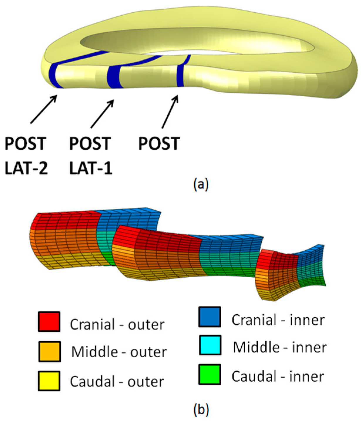
| POST | Cranial | - | - | - | - |
| Middle | * | * | * | - | |
| Caudal | * | * | - | - | |
| Inner | * | * | * | - | |
| Outer | - | * | - | - | |
| POST LAT-1 | Cranial | - | - | - | - |
| Middle | * | * | - | - | |
| Caudal | * | * | - | - | |
| Inner | * | * | - | - | |
| Outer | - | - | - | - | |
| POST LAT-2 | Cranial | * | - | * | - |
| Middle | * | - | * | - | |
| Caudal | * | * | - | * | |
| Inner | * | * | - | - | |
| Outer | * | - | - | - |
| Loading Scenario (Case No.) | Large AFF | Small AFF | Large EPJF | Small EPJF | Total Score 1 |
|---|---|---|---|---|---|
| 1 | 6 | 0 | 6 | 0 | 12 |
| 2 | 4 | 0 | 3 | 3 | 8.5 |
| 3 | 4 | 1 | 3 | 0 | 7.5 |
| 4 | 1 | 4 | 1 | 1 | 4.5 |
| 5 | 0 | 0 | 0 | 0 | 0 |
© 2017 by the authors. Licensee MDPI, Basel, Switzerland. This article is an open access article distributed under the terms and conditions of the Creative Commons Attribution (CC-BY) license ( http://creativecommons.org/licenses/by/4.0/).
Share and Cite
Casaroli, G.; Villa, T.; Bassani, T.; Berger-Roscher, N.; Wilke, H.-J.; Galbusera, F. Numerical Prediction of the Mechanical Failure of the Intervertebral Disc under Complex Loading Conditions. Materials 2017, 10, 31. https://doi.org/10.3390/ma10010031
Casaroli G, Villa T, Bassani T, Berger-Roscher N, Wilke H-J, Galbusera F. Numerical Prediction of the Mechanical Failure of the Intervertebral Disc under Complex Loading Conditions. Materials. 2017; 10(1):31. https://doi.org/10.3390/ma10010031
Chicago/Turabian StyleCasaroli, Gloria, Tomaso Villa, Tito Bassani, Nikolaus Berger-Roscher, Hans-Joachim Wilke, and Fabio Galbusera. 2017. "Numerical Prediction of the Mechanical Failure of the Intervertebral Disc under Complex Loading Conditions" Materials 10, no. 1: 31. https://doi.org/10.3390/ma10010031