Influence of Particle Size on Compressive Strength of Alkali Activated Refractory Materials


Slovenian National Building and Civil Engineering Institute, Dimičeva ulica 2, 1000 Ljubljana, Slovenia
*
Authors to whom correspondence should be addressed.
Materials 2020, 13(10), 2227; https://doi.org/10.3390/ma13102227
Submission received: 14 April 2020
/
Revised: 30 April 2020
/
Accepted: 8 May 2020
/
Published: 12 May 2020
(This article belongs to the Section Construction and Building Materials)
Abstract
:Influence of particle size on the mechanical strength of alkali activated material from waste refractory monolithic was investigated in this study. Precursor was chemically and mineralogically analysed, separated on 4 fractions and alkali activated with Na-water glass. Alkali activated materials were thoroughly investigated under SEM and XRD to evaluate the not predicted differences in mechanical strength. Influence of curing temperature and time dependence at curing temperatures on mechanical strength were investigated in the sample prepared from a fraction that caused the highest compressive strength.
Keywords:
refractory materials; alkali activation; particle size; SEM; EDXS; XRF; XRD; compressive strength1. Introduction
Alkali activated materials (AAM) are prepared from precursors that are rich in amorphous Si and Al. When the precursor and liquid alkali are mixed, dissolution of ingredients takes place, followed by diffusion and rearranging of chemical elements into monomer and finally into polymer aluminosilicate network (ASN) made from SiO4 and AlO4 tetrahedrons that are linked by O-bridges. Negative charge of Al in the ASN is compensated with positive ions from the 1st group of the periodic system from the alkali and with positive ions present in the precursor that get dissolved in the liquid mixture [1]. AAM represents potential future replacement of nowadays products for and from building industry, i.e., for cement, mortar, concrete, bricks, fire-resistant panels, pavements, ceramics [2,3,4,5,6,7,8], etc. The cost of these products is lowered due to using waste material instead of raw materials, i.e., no excavating of raw materials, no need for dumping waste in the municipal dumps, no need for downcycling and recycling because waste material becomes new raw material which is then upcycled with less need for energy and in a shorter time than conventional products [9,10,11].
When using waste material as the precursor, the material itself can contain ingredients that react with aqueous alkali with gas release, resulting in alkali activated self-foam (AAsF). This reaction can take place instantly or has a delayed effect (AAdF).
Influence of particle size on compressive strength of AAM was published in several papers stating that smaller the precursor’s particles, higher the compressive strength [12,13,14,15,16,17,18,19]. This effect was also investigated in connection to the synthesis of alkali activated foam, where the same dependence was found, i.e., smaller the particles, higher the compressive strength [20,21]. In addition with small enough particles in the slurry, slurry goes from Bingham plastic to Newtonian liquid, viscosity decreases and larger pores form (easier escape of the gasses from the slurry).
In this paper, refractory monolithic was investigated regarding their suitability for alkali activation, and specific focus has been put on the influence of particle size on the mechanical properties of AAM. Monolitics are materials that have no definite shape, can be used on-site for repair or construction of furnaces; consist of aggregates, binders and fillers [22].
2. Materials and Methods
2.1. Analysis of Precursor and Its Alkali Activated Counterpart
Refractory material (RM), labelled 16 11 06, i.e., waste refractory monolithics for the steel, iron, cement and heat industries, was collected in a manner to be representative of waste dump pile at company Termit, where 1500 t of this waste is collected per year.
Dried (70 °C for 24 h in heating chamber WTB Binder), ground (with the vibrating disk mill Siebtechnik TS250, Siebtechnik GmbH, Mülheim an der Ruhr, Germany) and sieved (below 125 µm) precursor was melted into discs (precursor was mixed with Fluxana(s) FX-X50-2, Fluxana GmbH & Co. KG, Bedburg-Hace, Germany, i.e., a mixture of Lithium tetraborate and Lithium metaborate (mass ratio 1:1), to lower the melting point, in mass ratio 1:10 for Fluxana; LiBr(l) (prepared from 50 mL H2O and 7.5 g of LiBr(s) from Acros Organics) was added to the mixture of precursor and Fluxana to avoid gluing of melt onto platinum vessel). On discs, X-ray fluorescence was performed (XRF; Thermo Scientific ARL Perform’X Sequential XRF, Thermo Fisher Scientific Inc., Walthem, MA, USA), measured data were analysed with software UniQuant 5 [version 5.00, Thermo Fisher Scientific Inc., Walthem, MA, USA].
X-ray powder diffraction (XRD; Empyrean PANalytical X-ray Diffractometer, Malvern PANalytical Empyrean, Netherlands and United Kingdom, Cu X-Ray source) was performed on the dried, ground and sieved (below 125 µm) precursor and alkali activated counterpart. XRD pattern was solved with software X’Pert Highscore plus 4.1 (4.1, Malvern PANalytical, Malvern, UK). Amount of amorphous phase and minerals were estimated with Rietveld refinement by using an external standard (pure corundum, Al2O3).
Surface, shape and microstructure investigation of un-sputtered dried (at 40 °C in vacuum for 24 h in Kambič heating chamber, VS 50 S) precursor and alkali activated materials was performed with the scanning electron microscope (SEM; Jeol JSM-IT500, Jeol, Tokyo, Japan) under high vacuum conditions. Energy-dispersive X-ray spectroscopy (EDXS; Oxford Instruments, Link Pentafet, London, UK) mapping of polished un-sputtered alkali activated samples were performed in low vacuum conditions.
Bending and compressive strength of alkali activated materials were measured with compressive and bending strength testing machine (ToniTechnik ToniNORM, Toni Technik, Berlin, Germany) 1 week after demoulding.
By weighting the alkali activated prisms and dividing its mass with its volume the geometrical densities of alkali activated materials were determined.
2.2. Preparation of Precursors, Activator and Alkali Activated Samples
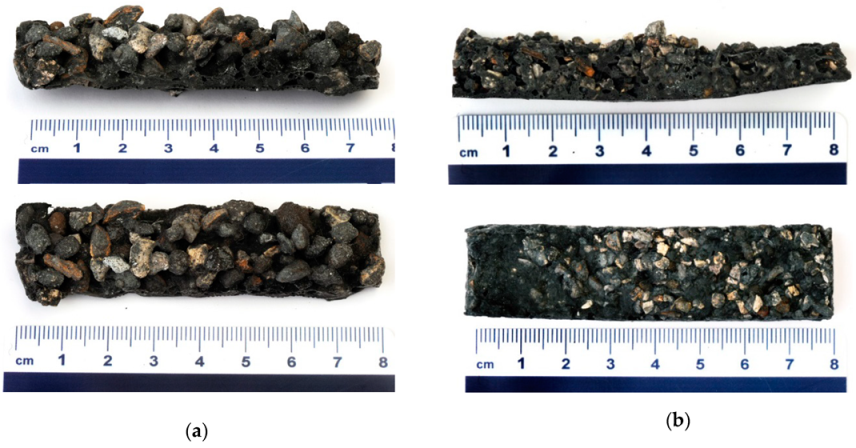
The precursor used for alkali activation was dried at 70 °C for 24 h and sieved afterwards into 4 fractions: above 4 mm (4 mm < x), between 2 mm and 4 mm (2 mm < x ≤ 4 mm), between 2 mm and 1 mm (1 mm < x ≤ 2 mm) and below 1 mm (x ≤ 1 mm), all shown in Figure 1. On all fractions of precursors, XRF and XRD measurements were performed in the manner described in Section 2.1. Fractions were alkali activated with Na-water glass (Geosil, 344/7, Woelner, with the mass percentage of Na2O 16.9 %, and mass percentage of SiO2 27.5 %) in mass ratio 50:30 for precursor (lower amount of alkali glass was not enough for wetting). Slurries were put into PVC moulds of size (80 × 20 × 20) mm3 and cured in heating chamber WTB Binder at 70 °C for 24 h. Prisms were demoulded after cooling down to room temperature and left at room temperature for an additional 7 days.
Alkali activated sample prepared from the fraction that had the highest compressive strength was additionally synthesized and cured at room conditions, at 40 °C and 70 °C for 7 days. Compressive strength was tested at days 7 and 28.
3. Results and Discussion
3.1. Analysis of Precursor
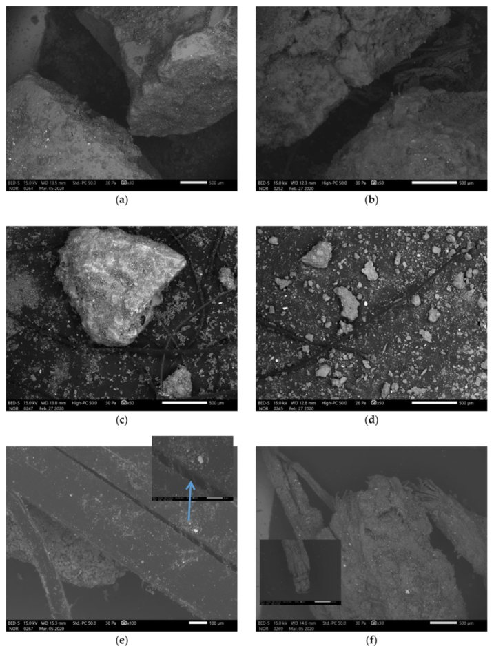
SEM micrographs of precursor prepared to be used in alkali activation are presented in Figure 2. All fractions contain polymer fibres and all contain small particles that are present on the surface of the bigger particles, on the fibres, aggregated as the fibre “glue” and are present as “dust” in all fractions (bigger fractions were not washed off fine powder). Particles’ shape is random with not a smooth surface and less sharp edges. Fibres in the biggest fraction are presented in Figure 2e, large single fibre splitting into smaller fibres and not completely split in the middle, with precursor on the surface, and in Figure 2f, a bundle of fibres completely wrapped in the precursor.
FTIR results of precursor sieved below 1 mm (without visible fibres) and of fibre without visible precursor on its surface, are presented in Figure 3. According to the literature [23] fibres are polyvinyl chloride (PVC; characteristic peaks are in the orange circle), which are resistant to diluted alkali [24].
Chemical analysis of all precursor’s fractions is presented in Table 1, where in 1st rows are mass percentages of elements crucial for alkali activation measured with XRF, in 2nd rows, mass percentages of elements crucial for alkali activation in crystalline phase measured with XRD and determined by means Rietveld refinement (GOF for all analysis around 8 (waste material)), in 3rd rows the mass percentage difference between the mass percentage of all elements crucial for alkali activation and mass percentage of elements crucial for alkali activation in the crystalline phase, i.e., the amount of amorphous phase. In all fractions, there is a small amount of elements from 1st and 2nd group of the periodic system, all except Ca are in the amorphous phase. Amorphous part of Ca represents the highest value among them, i.e., in all fractions more than 1 mass % (m%). As a good potential precursor for alkali activation, it does contain a decent amount of Al and Si, both in the crystalline and amorphous phase. However, there is (in all fractions) more Al than Si meaning that according to the literature [25] material has the tendency to foam, as there is always Si:Al ≤ 1.40 (0.70, 0.81, 0.82, 0.86 from biggest to smallest fraction if all amorphous material is accessible in the reaction and if minerals do not dissolve in alkali).
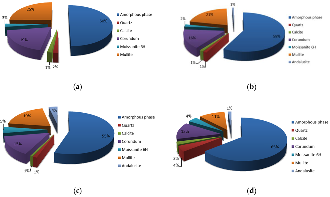
In Figure 4 are presented the XRD analysis of all precursor’s fractions and in Figure 5 their Rietveld refinement results. Amount of amorphous phase increases with smaller fraction of the precursor, also the amount of mullite. Amount of moissanite, calcite and andalusite is in all fractions similar, while the amount of quartz is highest in the smallest precursor’s fraction (other fractions have a comparable amount of quartz), and amount of corundum is biggest in the largest precursor’s fraction (other fractions have a comparable amount of corundum). On XRD patterns presented in Figure 4 is a peak (between 21° and 22°) present in all fractions which could not have been determined.
3.2. Analysis of Alkali Activated Samples Prepared from Different Precursor’s Fractions
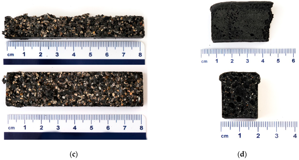
Compressive and bending strength of all alkali activated samples prepared from different fractions of the precursor are presented in Table 2 along with the density of the final products. Density and mechanical strengths grow from largest to 2nd smallest precursor (particles from 1 mm to 2 mm, blue row in Table 2), which is in agreement with the literature [16], but declines drastically when precursor’s fraction gets below 1 mm, which contradicts literature [16]. The 2nd smallest precursor’s fraction had from more than 3-times higher compressive strength from the smallest precursor’s fraction, while density declined only for just more than 1/3, indicating that self-foaming (chemical reaction with alkali) played a bigger role in the alkali activated synthesis, i.e., more sample reacted (due to bigger available precursor’s surface) and there was not enough free space between not yet reacted inner part of the precursor’s particles to allow gasses to escape without being trapped (creating pores) in the structure. Self-foaming was observed in alkali activation of the precursor with particle’s fraction below 1 mm, which is the reason for lower compressive strength in comparison to the alkali activated material synthesized from bigger fractions.
In Figure 6 are presented photographs of all alkali activated refractory material fraction’s where the largest 3 fractions are bonded together in the ASN, while the smallest fraction (Figure 5d) has a completely different structure, i.e., porous and almost completely reacted.
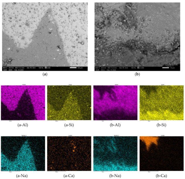
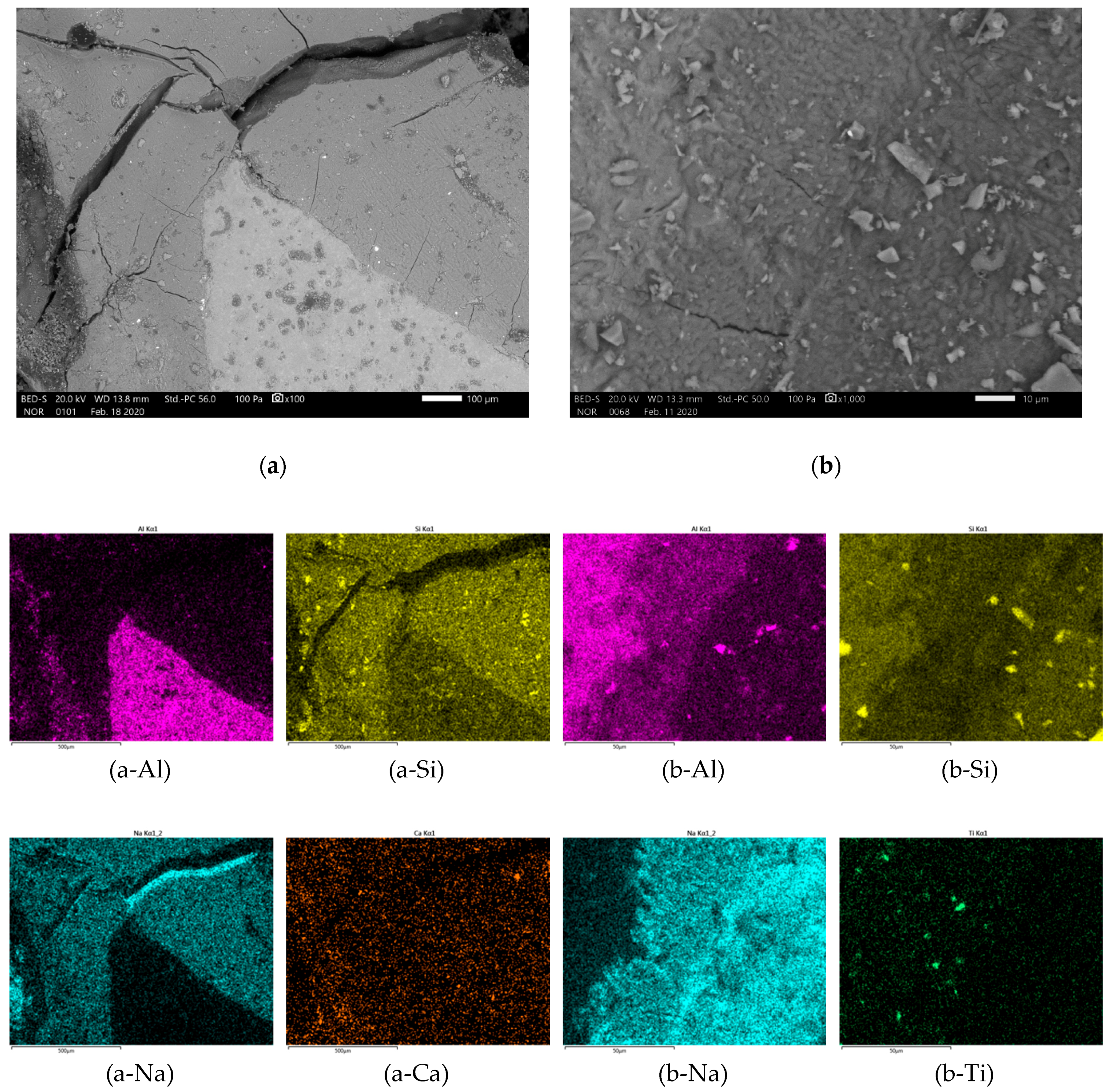
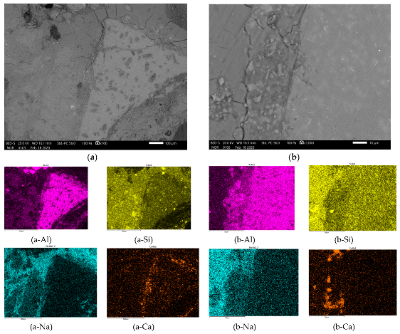
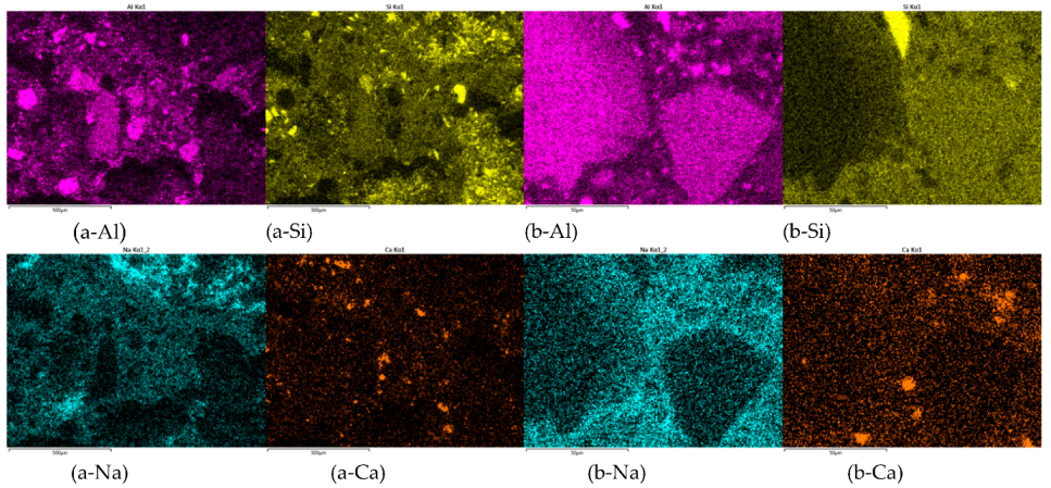
In Figure 7, Figure 8, Figure 9 and Figure 10 is presented polished unsputtered cross-sections of alkali activated material prepared from precursor’s fraction above 4 mm (4 mm < x), between 2 and 4 mm (2 mm < x ≤ 4 mm), 1 and 2 mm (1 < x ≤ 2 mm) and below 1 mm (x ≤ 1 mm), respectively. As it is obvious in Figure 6 that alkali activation of all fractions above 1 mm particle’s size resulted in AAM consisting of non-reacted precursor’s particles and “binder” connecting them (large Al particles did not dissolve; therefore reaction could take place only on the surface of particles), also SEM micrographs (Figure 7, Figure 8 and Figure 9) show comparable results: darker grey part presents ASN consisting mostly of Si and Na, while white parts present not-dissolved Al. Cracks (lower the mechanical strength) are present only in ASN due to curing and chemical reactions throughout the whole ASN independently on the presence of the not-reacted precursor’s particles: cracks can be perpendicular, longitudinal on the border ASN and not-reacted precursor, or the border can be chemically “erased” due to the chemical reaction binding ASN and not-reacted precursor, which is presented on Figure 8b and its EDXS analysis.
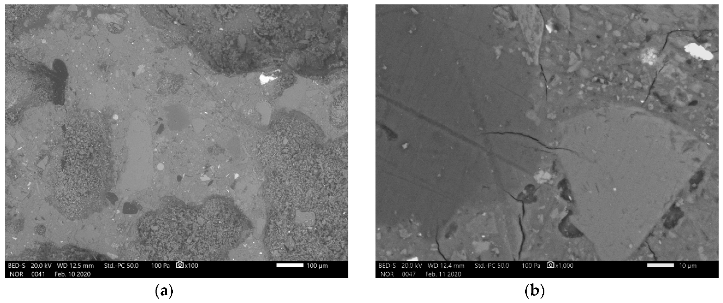
AAM from smallest precursor’s fraction (Figure 10) has visible cracks, present in ASN, only under higher magnification, but has large pores (lower the density and mechanical strength of AAM) visible under low magnification. ASN contains also not-reacted precursor’s particles which are spread throughout the ASN and are well incorporated in it. Smaller and fewer cracks present in the ASN in comparison to AAM from larger precursor’s fractions are a consequence of gasses getting trapped in the slurry and later in the hardened ASN, giving pressure onto the ASN structure also from the inside and not creating additional cracks through which gasses and liquid escaped while curing/drying took place.
With control of the particle’s size of precursor, it is possible also to control packing of the particles, i.e., the smaller the particles the closer the packing, which results in higher mechanical strength (experiment from precursor’s particles between 1 mm and 2 mm). With particles’ size, it is also possible to control the size of the voids which allow the escape of gasses or get filled with dissolved material in the slurry from which ASN forms.
In Figure 11 are presented SEM micrographs of unpolished AAM after bending strength measurement from all precursor’s fractions. Artificial fibres did not react with alkali, but due to the small precursor’s particles being present on its surface, it got well incorporated into the AAM. It is predicted that fibres offer increased bending strength, but since they cannot be completely removed (are present in all fractions) an experiment without fibres is not possible.
In Figure 12 are presented Rietveld refinement (GOF around 7 for all analysis) results for AAM from all fractions. Comparison of amounts of amorphous phase and minerals present in AAM from different fractions shows similar dependence to amounts present in the precursor’s fractions.
3.3. Analysis of Alkali Activated Sample Cured at Different Temperatures
Highest compressive and bending strength among all alkali activated samples prepared from different fractions had the sample that was prepared from precursor’s fraction between 1 mm and 2 mm (see Table 2). This fraction was alkali activated again in the same manner, just curing was performed on different temperatures (room conditions, 40 °C and 70 °C) for longer time (7 days instead of 1 day). Mechanical strengths of these samples measured at day 7 and 28 are presented in Table 3. Alkali activated material cured at room temperature did not gain measurable mechanical strengths at 7 days (it was not solidified yet), but it gained it at 28 days when both strengths were still much lower comparing to the samples treated at higher curing temperatures. From the Table 3, it is also obvious that the higher the temperature, higher the compressive and bending strengths at 7 and 28 days and the longer the time after moulding, the higher the mechanical strengths [26]. According to the ratio of the increase of mechanical strength over the time, we can conclude, that mechanical strengths are near the maximal value, while samples cured at lower temperatures still need much more time to reach the limit value. When comparing sample cured at 70 °C for 1 day and left at room conditions for an additional 6 days (Table 2), and cured at 70 °C for 7 days (Table 3), sample cured on a higher temperature for a longer time reached 80 % of compressive strength of sample cured on the same temperature for a shorter time.
3.4. Proposed Mechanism behind AAM Structure from Different Precursor’s Fractions
From photos and SEM micrographs of AAM, prepared from different precursor’s fractions, presented in Section 3.2., it is obvious that self-foaming effect showed high impact only in the fraction below 1 mm, i.e., in the smallest fraction. Diffusion of dissolved precursor’s compounds and their distribution have an important impact in “polymerization” in alkali activated synthesis, and should be limited to the local surroundings (diffusion limited “aggregation”) to gain faster solidification (property desired in the industry). This can be gained with the addition of the lowest amount of liquid possible to the precursor, i.e., to have highest possible viscosity of the slurry (drying needs less time and diffusion is limited with high viscosity) [26], that still offers in this short reactive time a sufficient bonding in the matrix. The unreacted part of particles serves as an aggregate which is chemically bonded with the matrix to certain degree depending on diffusion of all reactive elements in the slurry.
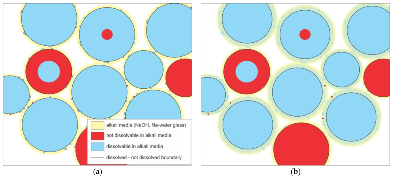
In Figure 13 are sketches of large (a–d) and small (e,f) fractions of the precursor from in alkali (yellow), dissolvable (blue) and not dissolvable (red) compounds. After wetting of the surface (Figure 13a,e) with alkali, blue compounds start to dissolve (to the black line marking the point to which dissolution is reached) and diffuse in the media (Figure 13b,f). With diffusion, the amount of Al and Si changes locally (seen on EDXS mapping of Al represented in Figure 8b-Al and Figure 9b-Al).
Gasses produced in the foaming reaction can be released into the large vacancies in the packing of the partially dissolved particles of precursors (seen also on photographs in Figure 6a–c). The foaming mechanisms which has not been definitely confirmed might be a consequence of partial dissolution of SiC (present in mineral Moissanite 6H) in alkali media [27] react with alkalis and oxygen and forms gas CO2. These gas(es) then shape the material from within with bubbles transforming AAM into alkali activated (self-)foam (AAsF).
4. Conclusions
Compressive and bending strength of alkali activated material showed unique dependence on refractory material’s particle’s fraction where down to certain fraction (down to 1 mm) mechanical strength is increasing, i.e., the smaller the particles, the bigger the reactive surface area in comparison to the volume, the higher reaction rate of the precursor and more reacted final material, which would make AAM with better mechanical strength if alkali activation would not cause precursor to foam, i.e., when alkali activating precursor has tendency to self-foam, the mechanical strength depends on the amount of reacted material and porous structure in the reacted material. If gases can be released from the AAM through the voids between particles in a larger fraction of the precursor, they do not affect the mechanical strength as much as when they destroy the compactness of the AAM leaving it with lower density, and lower compressive and bending strength. Highest mechanical strength had a sample with fraction 1 mm < x < 2 mm, which had the best close packing of not-reacted precursor’s particles and still was not influenced by foaming effect. Mechanical strength of AAM shows dependence on curing temperature and time after AAM synthesis. The higher the temperature and the longer the time after synthesis, the higher the mechanical strength.
Author Contributions
Conceptualization, B.H. and V.D.; data curation, B.H. formal analysis, B.H.; funding acquisition, V.D.; investigation, B.H.; methodology, B.H. and V.D.; supervision, V.D.; validation, B.H.; visualization, B.H.; writing—original draft, B.H.; writing—review and editing, B.H. and V.D. All authors have read and agreed to the published version of the manuscript.
Funding
Project No. C3330-17-529032 “Raziskovalci-2.0-ZAG-529032” was granted by Ministry of Education, Science and Sport of Republic of Slovenia. The investment is co-financed by the Republic of Slovenia, Ministry of Education, Science and Sport and the European Regional Development Fund. The involvement of V. Ducman was supported by the Slovenian Research Agency Programme Group P2-0273.
Acknowledgments
The Metrology Institute of the Republic of Slovenia is acknowledged for the use of XRF. Cooperation with Termit d.d. and Alenka Sešek Pavlin from Termit d.d.is highly appreciated. Mojca Mušič is grately thanked for the photos.
Conflicts of Interest
The authors declare no conflict of interest. The funders had no role in the design of the study; in the collection, analyses, or interpretation of data; in the writing of the manuscript, or in the decision to publish the results.
References
- Škvára, F. Alkali Activated Material-Geopolymer; ICT Prague: Prague, Czech Republic, 2007; p. 16. [Google Scholar]
- Glasby, T.; Day, J.; Genrich, R.; Aldred, D.J. EFC Geopolymer Concrete Aircraft Pavements at Brisbane West Wellcamp Airport. Concrete 2015, 2015, 9. [Google Scholar]
- Sanjayan, J.G.; Nazari, A.; Chen, L.; Nguyen, G.H. Physical and mechanical properties of lightweight aerated geopolymer. Constr. Build. Mater. 2015, 79, 236–244. [Google Scholar] [CrossRef]
- Ducman, V.; Kramar, S.; Šajna, A. Alkali activated repair mortars based on different precursors. In Eco-Efficient Repair and Rehabilitation of Concrete Infrastructures; Elsevier: Duxford, UK, 2018; pp. 263–292. ISBN 978-0-08-102181-1. [Google Scholar]
- Kargin, A.; Baev, V.; Mashkin, N. Fly-Ash Geo-Polymer Foamed Concrete. In AIP Conference Proceedings; AIP Publishing LLC: Melville, NY, USA, 2017; p. 020005. [Google Scholar] [CrossRef]
- Ahmari, S.; Allahverdi, A.; Alonso, M.M.; Baklouti, S.; Balomenos, E.; Barbieri, L.; Barroso de Aguiar, J.; Baščarević, Z.; Bernal, S.A.; Borrachero, M.V.; et al. Handbook of Alkali-Activated Cements, Mortars and Concretes; Elsevier: Amsterdam, The Netherlands, 2015; ISBN 978-1-78242-276-1. [Google Scholar]
- Fernandez-Jimenez, A.; García-Lodeiro, I.; Palomo, A. Durability of alkali-activated fly ash cementitious materials. J. Mater. Sci. 2007, 42, 3055–3065. [Google Scholar] [CrossRef]
- Al Bakri, A.M.M.; Kamarudin, H.; Binhussain, M.; Khairul Nizar, I.; Rafiza, A.R.; Zarina, Y. Comparison of geopolymer fly ash and ordinary portland cement to the strength of concret. Adv. Sci. Lett. 2013, 19, 3592–3595. [Google Scholar] [CrossRef]
- Provis, J.L. Alkali-activated materials. Cem. Concr. Res. 2018, 114, 40–48. [Google Scholar] [CrossRef]
- Shi, C.; Qian, J. High performance cementing materials from industrial slags—A review. Resour. Conserv. Recycl. 2000, 29, 195–207. [Google Scholar] [CrossRef]
- Abdollahnejad, Z.; Pacheco-Torgal, F.; Félix, T.; Tahri, W.; Barroso Aguiar, J. Mix design, properties and cost analysis of fly ash-based geopolymer foam. Constr. Build. Mater. 2015, 80, 18–30. [Google Scholar] [CrossRef] [Green Version]
- Furlani, E.; Maschio, S.; Magnan, M.; Aneggi, E.; Andreatta, F.; Lekka, M.; Lanzutti, A.; Fedrizzi, L. Synthesis and characterization of geopolymers containing blends of unprocessed steel slag and metakaolin: The role of slag particle size. Ceram. Int. 2018, 44, 5226–5232. [Google Scholar] [CrossRef]
- Isabella, C.; Lukey, G.C.; Xu, H. The Effect of Aggregate Particle Size on Formation of Geopolymeric Gel. In Engineering Conferences International; ECI Digital Archives: New York, NY, USA, 2003. [Google Scholar]
- Traven, K.; Češnovar, M.; Ducman, V. Particle size manipulation as an influential parameter in the development of mechanical properties in electric arc furnace slag-based AAM. Ceram. Int. 2019, 45, 22632–22641. [Google Scholar] [CrossRef]
- Petrakis, E.; Karmali, V.; Bartzas, G.; Komnitsas, K. Grinding Kinetics of Slag and Effect of Final Particle Size on the Compressive Strength of Alkali Activated Materials. Minerals 2019, 9, 714. [Google Scholar] [CrossRef] [Green Version]
- Petrakis, E.; Karmali, V.; Komnitsas, K. Effect of Particle Size on Alkali-Activation of Slag. Int. J. Mater. Metall. Eng. 2019, 13, 4. [Google Scholar]
- Assi, L.N.; Eddie Deaver, E.; Ziehl, P. Effect of source and particle size distribution on the mechanical and microstructural properties of fly Ash-Based geopolymer concrete. Constr. Build. Mater. 2018, 167, 372–380. [Google Scholar] [CrossRef]
- Azevedo, A.G.S.; Strecker, K.; Barros, L.A.; Tonholo, L.F.; Lombardi, C.T. Effect of Curing Temperature, Activator Solution Composition and Particle Size in Brazilian Fly-Ash Based Geopolymer Production. Mater. Res. 2019, 22. [Google Scholar] [CrossRef] [Green Version]
- Wiyono, D.; Vianthi, A.; Putra, P.; Kartadinata, G.; Hardjito, D. Effect of Particle Size on Properties of Sidoarjo Mud-Based Geopolymer. Mater. Sci. Forum 2014, 803, 44–48. [Google Scholar] [CrossRef]
- Beghoura, I.; Castro-Gomes, J. Design of alkali-activated aluminium powder foamed materials for precursors with different particle sizes. Constr. Build. Mater. 2019, 224, 682–690. [Google Scholar] [CrossRef]
- Szabó, R.; Gombkötő, I.; Svéda, M.; Mucsi, G. Effect of Grinding Fineness of Fly Ash on the Properties of Geopolymer Foam. Arch. Metall. Mater. 2017, 62, 1257–1261. [Google Scholar] [CrossRef] [Green Version]
- Type of Monolithic Refractories. Available online: http://www.idc-online.com/technical_references/pdfs/mechanical_engineering/Type_of_Monolithic_Refractories.pdf (accessed on 26 February 2020).
- Guo, J.-W.; Lin, Z.-Y.; Huang, B.-R.; Lu, C.-H.; Chen, J.-K. Antigen detection with thermosensitive hydrophilicity of poly(N -isopropylacrylamide)-grafted poly(vinyl chloride) fibrous mats. J. Mater. Chem. B 2018, 6, 3486–3496. [Google Scholar] [CrossRef] [PubMed]
- Polyvinyl Chloride PVC. Available online: https://www.bpf.co.uk/plastipedia/polymers/pvc.aspx (accessed on 5 March 2020).
- Duxson, P.; Provis, J.L.; Lukey, G.C.; Mallicoat, S.W.; Kriven, W.M.; van Deventer, J.S.J. Understanding the relationship between geopolymer composition, microstructure and mechanical properties. Colloids Surfaces A Physicochem. Eng. Asp. 2005, 269, 47–58. [Google Scholar] [CrossRef]
- Horvat, B.; Ducman, V. Potential of Green Ceramics Waste for Alkali Activated Foams. Materials 2019, 30, 3563. [Google Scholar] [CrossRef] [PubMed]
- Eremenko, B.V.; Shumovskaya, E.F. Reactions of aqueous silicon carbide suspensions with an acid and an alkali. Sov. Powder Metall. Metal Ceram. 1972, 11, 815–818. [Google Scholar] [CrossRef]
Figure 1.
Photographs of refractory material (RM) sieved (a) above 4 mm, (b) between 2 mm and 4 mm, (c) between 1 mm and 2 mm and (d) below 1 mm.
Figure 1.
Photographs of refractory material (RM) sieved (a) above 4 mm, (b) between 2 mm and 4 mm, (c) between 1 mm and 2 mm and (d) below 1 mm.

Figure 2.
SEM micrographs of RM sieved (a,e,f) above 4 mm, (b) between 2 mm and 4 mm, (c) between 1 mm and 2 mm and (d) below 1 mm.
Figure 2.
SEM micrographs of RM sieved (a,e,f) above 4 mm, (b) between 2 mm and 4 mm, (c) between 1 mm and 2 mm and (d) below 1 mm.

Figure 3.
FTIR measurement of precursor sieved below 1 mm (blue line), and fibre (orange line).

Figure 4.
XRD pattern of precursor’s fraction above 4 mm (red line), between 2 mm and 4 mm (green line), between 1 mm and 2 mm (blue line) and below 1 mm (orange line). In the legend, minerals are: quartz (SiO2, card number ICSD 98-015-6196), calcite (CaCO3, card number ICSD 98-015-8258), corundum (Al2O3, card number ICSD 98-016-0604), moissanite 6H (SiC, card number ICSD 98-015-6190), mullite (Al1.83O4.85Si1.08, card number ICSD 98-004-3298) and alusite (Al2SiO5, card number ICSD 98-008-4614).

Figure 5.
Rietveld refinement of precursor’s fraction (a) above 4 mm, (b) between 2 mm and 4 mm, (c) between 1 mm and 2 mm and (d) below 1 mm.
Figure 5.
Rietveld refinement of precursor’s fraction (a) above 4 mm, (b) between 2 mm and 4 mm, (c) between 1 mm and 2 mm and (d) below 1 mm.
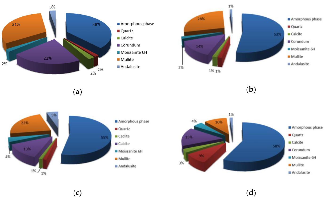
Figure 6.
Photographs of RM sieved (a) above 4 mm, (b) between 2 mm and 4 mm, (c) between 1 mm and 2 mm and (d) below 1 mm.
Figure 6.
Photographs of RM sieved (a) above 4 mm, (b) between 2 mm and 4 mm, (c) between 1 mm and 2 mm and (d) below 1 mm.


Figure 7.
SEM micrograph of alkali activated material prepared from precursor’s fraction 4 mm < x with magnification of (a) 100 and (b) 1000. EDXS mapping is presented in (a/b-chemical element) of area (a/b), respectively.
Figure 7.
SEM micrograph of alkali activated material prepared from precursor’s fraction 4 mm < x with magnification of (a) 100 and (b) 1000. EDXS mapping is presented in (a/b-chemical element) of area (a/b), respectively.

Figure 8.
SEM micrograph of alkali activated material prepared from precursor’s fraction 2 mm < x ≤ 4 mm with magnification of (a) 100 and (b) 1000. EDXS mapping is presented in (b-chemical element) of area (b).
Figure 8.
SEM micrograph of alkali activated material prepared from precursor’s fraction 2 mm < x ≤ 4 mm with magnification of (a) 100 and (b) 1000. EDXS mapping is presented in (b-chemical element) of area (b).

Figure 9.
SEM micrograph of alkali activated material prepared from precursor’s fraction 1 mm < x ≤ 2 mm with magnification of (a) 100 and (b) 1000. EDXS mapping is presented in (b-chemical element) of area (b).
Figure 9.
SEM micrograph of alkali activated material prepared from precursor’s fraction 1 mm < x ≤ 2 mm with magnification of (a) 100 and (b) 1000. EDXS mapping is presented in (b-chemical element) of area (b).

Figure 10.
SEM micrograph of alkali activated material prepared from precursor’s fraction x ≤ 1 mm with magnification of (a) 100 and (b) 1000. EDXS mapping is presented in (b-chemical element) of area (b).
Figure 10.
SEM micrograph of alkali activated material prepared from precursor’s fraction x ≤ 1 mm with magnification of (a) 100 and (b) 1000. EDXS mapping is presented in (b-chemical element) of area (b).


Figure 11.
SEM micrographs of unpolished alkali activated materials (AAM) after bending strength measurement from precursor sieved (a) above 4 mm, (b) between 2 mm and 4 mm, (c) between 1 mm and 2 mm and (d) below 1 mm.
Figure 11.
SEM micrographs of unpolished alkali activated materials (AAM) after bending strength measurement from precursor sieved (a) above 4 mm, (b) between 2 mm and 4 mm, (c) between 1 mm and 2 mm and (d) below 1 mm.

Figure 12.
Rietveld refinement of alkali activated materials from fraction of precursor (a) above 4 mm, (b) between 2 mm and 4 mm, (c) between 1 mm and 2 mm and (d) below 1 mm.
Figure 12.
Rietveld refinement of alkali activated materials from fraction of precursor (a) above 4 mm, (b) between 2 mm and 4 mm, (c) between 1 mm and 2 mm and (d) below 1 mm.

Figure 13.
Sketches of early alkali activation process from big (a–d) and small (e,f) precursor. The 1st step (a,e) is wetting of the precursor’s surface, 2nd step (c,d,f) is the dissolution of in alkali dissolvable precursor’s ingredients accompanied by diffusion of dissolved ions.
Figure 13.
Sketches of early alkali activation process from big (a–d) and small (e,f) precursor. The 1st step (a,e) is wetting of the precursor’s surface, 2nd step (c,d,f) is the dissolution of in alkali dissolvable precursor’s ingredients accompanied by diffusion of dissolved ions.


Table 1.
1st row of precursor’s fractions presents the mass percentage of elements measured with X-ray fluorescence (XRF), 2nd row mass percentage of elements in the crystalline phase that was determined with Rietveld refinement from XRD, 3rd row mass percentage of elements in the amorphous phase.
Table 1.
1st row of precursor’s fractions presents the mass percentage of elements measured with X-ray fluorescence (XRF), 2nd row mass percentage of elements in the crystalline phase that was determined with Rietveld refinement from XRD, 3rd row mass percentage of elements in the amorphous phase.
| Precursor’s Fraction | Elements [m%] | Na | K | Cs | Mg | Ca | Sr | Ba | Al | Si |
|---|---|---|---|---|---|---|---|---|---|---|
| 4 mm < x | XRF | 0.20 | 0.21 | 0 | 0.62 | 2.19 | 0.04 | 0.20 | 32.71 | 12.61 |
| XRD | 0 | 0 | 0 | 0 | 0.88 | 0 | 0 | 22.59 | 5.56 | |
| XRF-XRD | 0.20 | 0.21 | 0 | 0.62 | 1.31 | 0.04 | 0.20 | 10.12 | 7.05 | |
| 2 mm < x ≤ 4 mm | XRF | 0.25 | 0.27 | 0 | 0.45 | 1.69 | 0.03 | 0.10 | 30.46 | 15.27 |
| XRD | 0 | 0 | 0 | 0 | 0.60 | 0 | 0 | 18.44 | 5.50 | |
| XRF-XRD | 0.25 | 0.27 | 0 | 0.45 | 1.09 | 0.03 | 0.10 | 12.02 | 9.77 | |
| 1 mm < x ≤ 2 mm | XRF | 0.24 | 0.29 | 0 | 0.40 | 2.04 | 0.03 | 0.13 | 30.05 | 16.83 |
| XRD | 0 | 0 | 0 | 0 | 0.44 | 0 | 0 | 17.56 | 6.56 | |
| XRF-XRD | 0.24 | 0.29 | 0 | 0.40 | 1.60 | 0.03 | 0.13 | 12.49 | 10.27 | |
| x ≤ 1 mm | XRF | 0.48 | 0.24 | 0 | 0.46 | 2.63 | 0.03 | 0.22 | 25.79 | 20.01 |
| XRD | 0 | 0 | 0 | 0 | 1.20 | 0 | 0 | 12.36 | 8.42 | |
| XRF-XRD | 0.48 | 0.24 | 0 | 0.46 | 1.43 | 0.03 | 0.22 | 13.43 | 11.59 |
Table 2.
The density of alkali activated samples, their compressive and bending strengths in dependence of precursor’s particles’ fraction.
Table 2.
The density of alkali activated samples, their compressive and bending strengths in dependence of precursor’s particles’ fraction.
| Precursor’s Fraction | Compressive Strength [MPa] | Bending Strength [MPa] | Density [kg/L] |
|---|---|---|---|
| 4 mm < x | 3.9 | 2.2 | 1.2 |
| 2 mm < x ≤ 4 mm | 14.1 | 5.3 | 1.3 |
| 1 mm < x ≤ 2 mm | 21.3 | 8.6 | 1.5 |
| x ≤ 1 mm | 6.4 | 3.5 | 0.9 |
Table 3.
The compressive and bending strengths of alkali activated samples from fraction 1 mm to 2 mm, in dependence of curing temperature and elapsed time.
Table 3.
The compressive and bending strengths of alkali activated samples from fraction 1 mm to 2 mm, in dependence of curing temperature and elapsed time.
| Curing Temperature for 7 Days | Compressive Strength after 7 Days [MPa] | Compressive Strength after 28 Days [MPa] | Bending Strength after 7 Days [MPa] | Bending Strength after 28 Days [MPa] |
|---|---|---|---|---|
| Room conditions | 0 | 1.8 | 0 | 1.9 |
| 40 °C | 2.4 | 4.1 | 0.05 | 3.6 |
| 70 °C | 17.4 | 20.4 | 7.6 | 9.0 |
© 2020 by the authors. Licensee MDPI, Basel, Switzerland. This article is an open access article distributed under the terms and conditions of the Creative Commons Attribution (CC BY) license (http://creativecommons.org/licenses/by/4.0/).
Share and Cite
MDPI and ACS Style
Horvat, B.; Ducman, V. Influence of Particle Size on Compressive Strength of Alkali Activated Refractory Materials. Materials 2020, 13, 2227. https://doi.org/10.3390/ma13102227
AMA Style
Horvat B, Ducman V. Influence of Particle Size on Compressive Strength of Alkali Activated Refractory Materials. Materials. 2020; 13(10):2227. https://doi.org/10.3390/ma13102227
Chicago/Turabian StyleHorvat, Barbara, and Vilma Ducman. 2020. "Influence of Particle Size on Compressive Strength of Alkali Activated Refractory Materials" Materials 13, no. 10: 2227. https://doi.org/10.3390/ma13102227
Note that from the first issue of 2016, this journal uses article numbers instead of page numbers. See further details here.