2.1. Macroscopic film properties
Table 1 shows the composition of the films and their thickness.
Table 2 summarizes their properties. Films 1 and 2, which are obtained from solutions with low PB content, contain macroscopic defects like holes and striations. These films cannot be detached from the substrate without breaking. Films 3 and 4 can be detached from the casting substrate, but film 4 is too thick for the intended use inside the NiTi tubes because defects on the order of ca. 5 μm should be detected, which can presumably not be seen anymore with a much thicker film such as film 4. As a result, further studies focused on Film 3 and variations thereof.
Table 1.
Film composition and thickness. PB is poly(butadiene), AIBN is Azo-bis-(isobutyronitrile), TRIS is trimethylolpropane tris(3-mercaptopropionate), and Fe is iron oxide nanoparticles.
Table 1.
Film composition and thickness. PB is poly(butadiene), AIBN is Azo-bis-(isobutyronitrile), TRIS is trimethylolpropane tris(3-mercaptopropionate), and Fe is iron oxide nanoparticles.
| Film | [PB]/wt% | [AIBN]/wt % | [TRIS] /wt % | [Fe]/wt% | Approximate film thickness/µm |
|---|
| 1 | 0.5 | 5.0 | 5.0 | 3.0 | 1.1 |
| 2 | 1.0 | 5.0 | 5.0 | 3.0 | 1.7 |
| 3 | 1.5 | 5.0 | 5.0 | 3.0 | 2.3 – 2.7 |
| 3a | 1.5 | - | - | - | - |
| 3b | 1.5 | - | - | 3.0 | - |
| 3c | 1.5 | 5.0 | 5.0 | - | - |
| 4 | 2.0 | 5.0 | 5.0 | 3.0 | > 4 |
| 5 | 1.5 | 5.0 | 5.0 | 1.0 | - |
| 6 | 1.5 | 5.0 | 5.0 | 3.0 | 2.3 – 2.7 |
| 7 | 1.5 | 5.0 | 5.0 | 6.0 | - |
| 8 | 1.5 | 5.0 | 1.0 | 3.0 | 2.0 – 3.0 |
| 8a | 1.5 | 5.0 | 1.0 | - | - |
| 9 | 1.5 | 5.0 | 3.0 | 3.0 | 2.0 – 3.0 |
| 9a | 1.5 | 5.0 | 3.0 | - | - |
| 10 | 1.5 | 5.0 | 5.0 | 3.0 | 2.3 – 2.7 |
| 10a | 1.5 | 5.0 | 5.0 | - | - |
| 11 | 1.5 | 5.0 | 10.0 | 3.0 | > 3.0 |
| 11a | 1.5 | 5.0 | 10.0 | - | - |
Not surprisingly,
Table 2 shows that uncrosslinked films cannot be removed from the substrates. This implies that the degree of crosslinking and possibly the presence of initiator (AIBN) and/or TRIS and MNPs affects the adhesion to the substrate. Kim
et al. [
10] previously investigated the influence of crosslinking degree of PB domains in mixtures of poly(styrene-butadiene-styrene) (SBS) block copolymer and tackifier on peel strength and adhesion. Both decrease with increasing crosslinking. Kim
et al. also suggested that excess amounts of initiator act as impurities near interfaces. These impurities reduce the wettability between film and substrate. Finally, higher initiator concentration means higher radical concentration during the long mixing period (30 h) which can affect the degree of crosslinking and thus decrease the peel strength.
Table 2.
Solubility, macroscopic appearance, and detachability of the films listed in
Table 1.
Table 2.
Solubility, macroscopic appearance, and detachability of the films listed in Table 1.
| Film | Gel fraction/wt% | Macroscopic appearance | Detachable from substrate |
|---|
| 3 | 56 ± 3 | Mostly homogeneous
Some irregularities | Yes |
| 3a | 0 | Homogeneous | No, disintegrates upon removal |
| 3b | 0 | Inhomogeneous | No, disintegrates upon removal |
| 3c | < 20 | Mostly homogeneous
Some irregularities | Only after 3 weeks of exposure to daylight |
| 5 | 37 ± 7 | Mostly homogeneous
Some irregularities | Partly
more fragile than films 6 and 7 |
| 6 | 56 ± 3 | Mostly homogeneous
Some irregularities | Yes |
| 7 | 58 ± 3 | Mostly homogeneous
Some irregularities | Yes |
| 8 | < 20 | Inhomogeneous | No |
| 8a | < 20 | Inhomogeneous | No |
| 9 | < 50 | Inhomogeneous | No |
| 9a | < 20 | Inhomogeneous | No |
| 10 | 56 ± 3 | Mostly homogeneous
Some irregularities | Yes |
| 10a | < 20 | Mostly homogeneous
Some irregularities | Only after 3 weeks of exposure to daylight |
| 11 | 73 ± 5 | Mostly homogeneous
Some irregularities | Yes |
| 11a | < 20 | Mostly homogeneous
Some irregularities | Only after 3 weeks of exposure to daylight |
Table 2 also shows that film 3c slowly crosslinks upon exposure to light and that the presence of iron oxide nanoparticles seems to enhance the crosslinking process. Indeed, El-Tantawy
et al. [
11] reported that Fe
3O
4 promotes crosslinking and that the degree of crosslinking increases as the concentration of Fe
3O
4 increases. In the current case, the presence of iron oxide nanoparticles is therefore advantageous for two reasons. First, it enhances the crosslinking reaction and second, it furnishes the films with a magnetic property, which is desired for the final application in the NiTi tubes,
Scheme 1.
For this latter point, a strong magnetic signal and hence a high concentration of the magnetic nanoparticles is desirable. Besides, the films need to be homogeneous and stable under regular handling conditions. To determine the influence of MNP concentration on film properties, films with different MNP concentrations were prepared. As film 3 has the most appropriate properties among films of different thickness, a PB concentration of 1.5 wt % in toluene was chosen for preparation of films 5 to 7,
Table 1 and
Table 2.
Table 2 shows that the gel fraction increases as MNP concentration increases. However, although film 7 contains twice as many iron oxide particles as film 6, the gel fraction does not increase over ca. 55 to 58 %, suggesting that there is a maximum degree of crosslinking which cannot be exceeded under the current conditions. Besides the high degree of crosslinking and high loading of magnetic nanoparticles, the homogeneity and stability of the films is important. Films 5 to 7 can be detached from the substrate, but film 5 is less stable and only partly detaches.
The effect of TRIS concentration was probed with films 8 to 11. The PB and Fe (from MNPs) concentrations are constant at 1.5 wt% and 3 wt%, because films 3 and 6 have been found to exhibit a suitable film thickness and homogeneous MNP distribution. Films 8 and 9 have an irregular macroscopic appearance, while films 10 and 11 are macroscopically homogeneous. If the MNPs are omitted during film formation (films 8a to 11a), but the TRIS concentrations are kept constant, the films only poorly crosslink and cannot be removed from the substrate. Only after three weeks of daylight irradiation, the degree of crosslinking (via an uncontrolled crosslinking process initiated by various irradiation conditions) is high enough to form detachable films. This observation illustrates that the MNPs not only provide the magnetic moment needed for the device to finally function, but also enhance the crosslinking reaction, similar to El Tantawy
et al. [
11] Overall, the presence of the irregularities described above (striations, holes, etc.) seems to depend on the TRIS concentration rather than the MNPs. Low TRIS concentrations lead to films of poor quality, whereas more strongly crosslinked films with higher TRIS concentrations are more homogeneous.
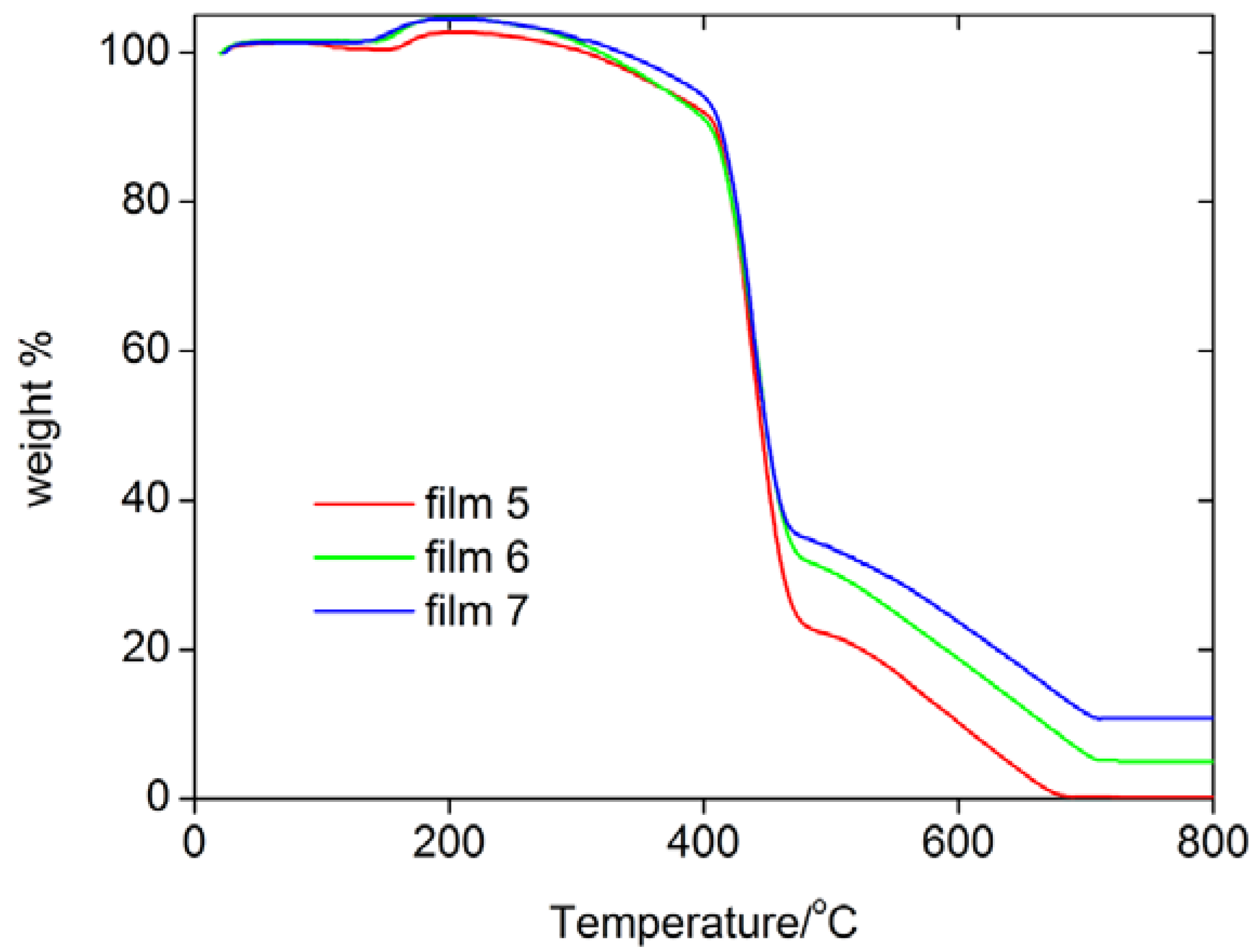
Figure 1 shows thermogravimetric analysis (TGA) data of some films. TGA shows that they essentially behave the same, that is, the incorporation of the MNPs does not significantly alter the thermal stability of the resulting hybrid films. TGA finds one rapid weight loss between 420 and 450 ºC, which is followed by a slower weight loss between 500 and 700 ºC. Differential thermal analysis (DTA) shows that both processes are exothermic processes, which suggests that the polymer is thermally decomposing and the remains are burning at higher temperatures. The remaining mass at 800 ºC differs depending on the weight of iron oxide particles loaded in the films.
Figure 1.
TGA curves of some films.
Figure 1.
TGA curves of some films.
2.2. Microscopic film homogeneity and MNP distribution
Essentially, films 3, 5, 6, 7, 10, and 11 have favorable macroscopic properties for the intended application: homogeneous morphology, high gel fraction, and easy detachability from the substrate. However, to determine the inner structure of the NiTi tubes, the distribution of the MNPs must also be homogeneous on a microscopic level and the films must also be microscopically homogeneous and stable.
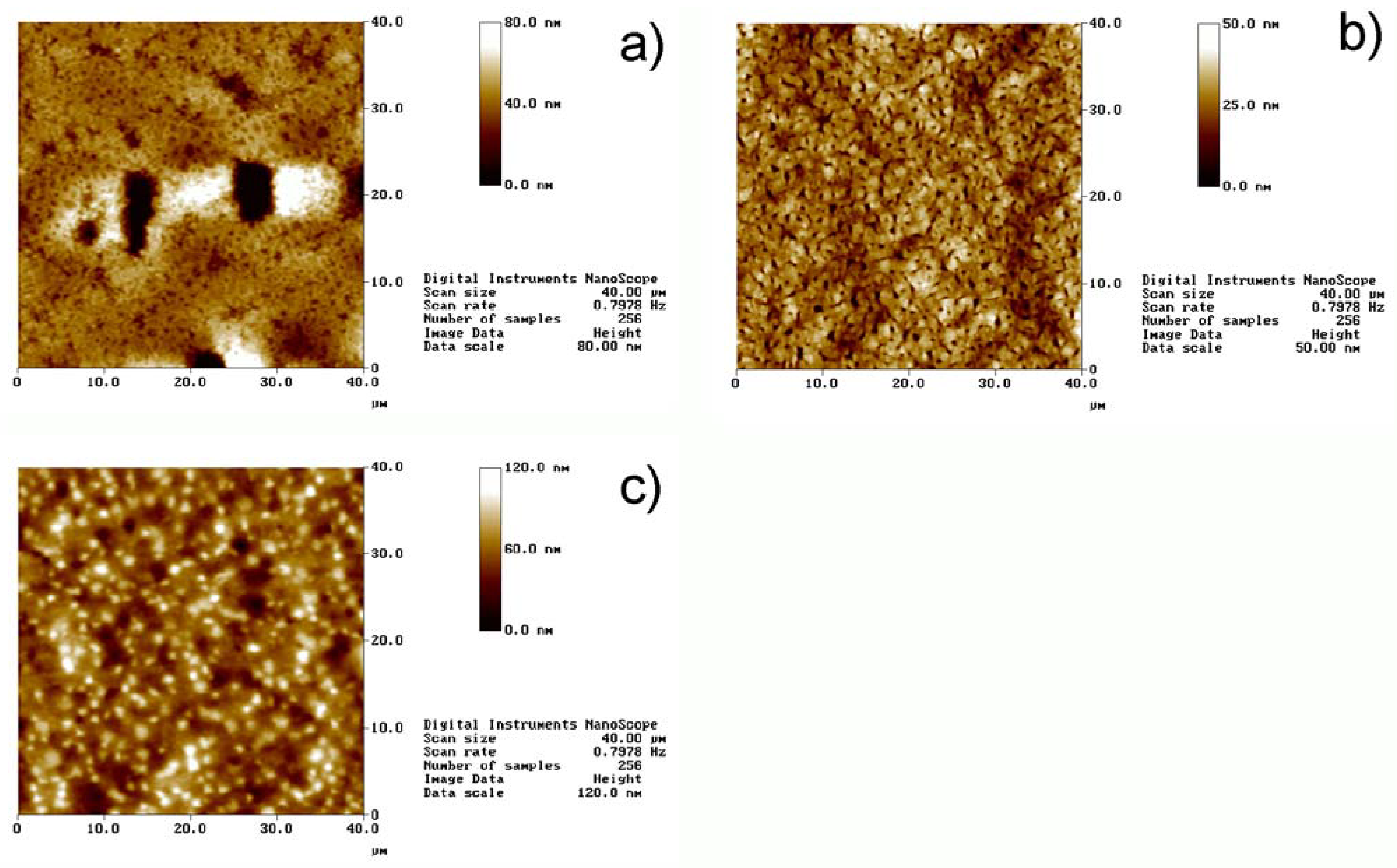
Figure 2 shows representative atomic force microscopy (AFM) images of films with different MNP fractions. Macroscopically inhomogeneous films show microscopic inhomogeneities like dents and elevated areas. The diameters of these features are up to ca. 20 μm in diameter and the depth or height reaches up to 500 nm. In contrast, macroscopically homogeneous films exhibit uniform surface topographies with only few smaller dents with a maximum depth of ca. 300 nm. The mean square (Rms) roughness for all the films is between 5 and 80 nm. The defect shown in
Figure 1a is an atypical case, as usually film 5 and also film 6 do not exhibit large defects. However, the image illustrates well the types of defects that can occur.
Figure 2.
AFM images of different films. a) Film 5, b) film 6, and c) film 7. Note that the height scales are different. The defect shown in
Figure 2a is atypical for Film 5 and was only observed very rarely. Regular surfaces of film 5 look like the area in the top third of the image. The defect was chosen to show the dimensions of such defects.
Film 7, that is, the film with the highest MNP concentration, exhibits numerous “dots” in the AFM images. These are assigned to some clustering of the MNPs at or near the surface, which is consistent with scanning electron microscopy data of the same films (data not shown). Indeed, Wilson
et al. [
12] have investigated the behavior of iron oxide particles in nanocomposites obtained by melt-blending and confirmed that nanoparticles tend to migrate under the surface. Gass
et al. [
13] confirmed the same behavior in spin-coated composites. We thus conclude that particle migration occurs in our films as well, including in film 7 where the concentration of MNPs is so high that numerous clustered particles form even on the surface.
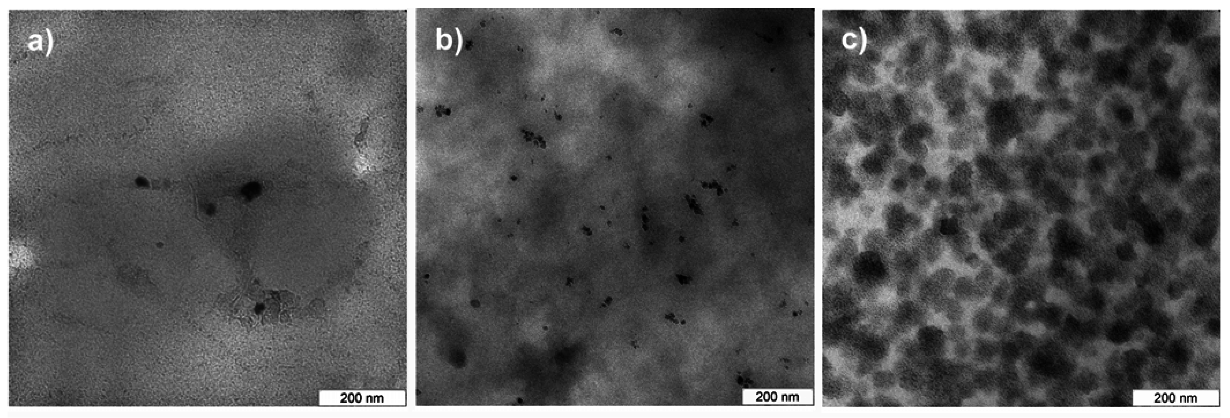
Figure 3 shows representative transmission electron microscopy (TEM) images of longitudinal thin sections of the films. TEM confirms AFM and shows that there are only a few nanoparticles in film 5. Particle aggregates consist of no more than 10 particles and are below 200 nm in size. Occasionally there are also larger areas without nanoparticles. Film 6 contains nanoparticles in all areas of the films studied. In film 7, the high nanoparticle concentration results in numerous agglomerates of around 80 nm in diameter. The agglomerates are connected, but there are other areas with very low nanoparticle density. This suggests that the AFM images indeed show MNP clusters at or near the surface of film 7. Overall, AFM and TEM show that film 6 has the best properties, that is, uniform MNP distribution, smooth and uniform micromorphology and uniform macromorphology for the desired application.
Figure 3.
TEM images of MNP distribution in a) film 5, b) film 6, and c) film 7. Sections are longitudinal thin sections, that is, sections in the plane of the film.
Figure 3.
TEM images of MNP distribution in a) film 5, b) film 6, and c) film 7. Sections are longitudinal thin sections, that is, sections in the plane of the film.
2.3. Swelling of the gels
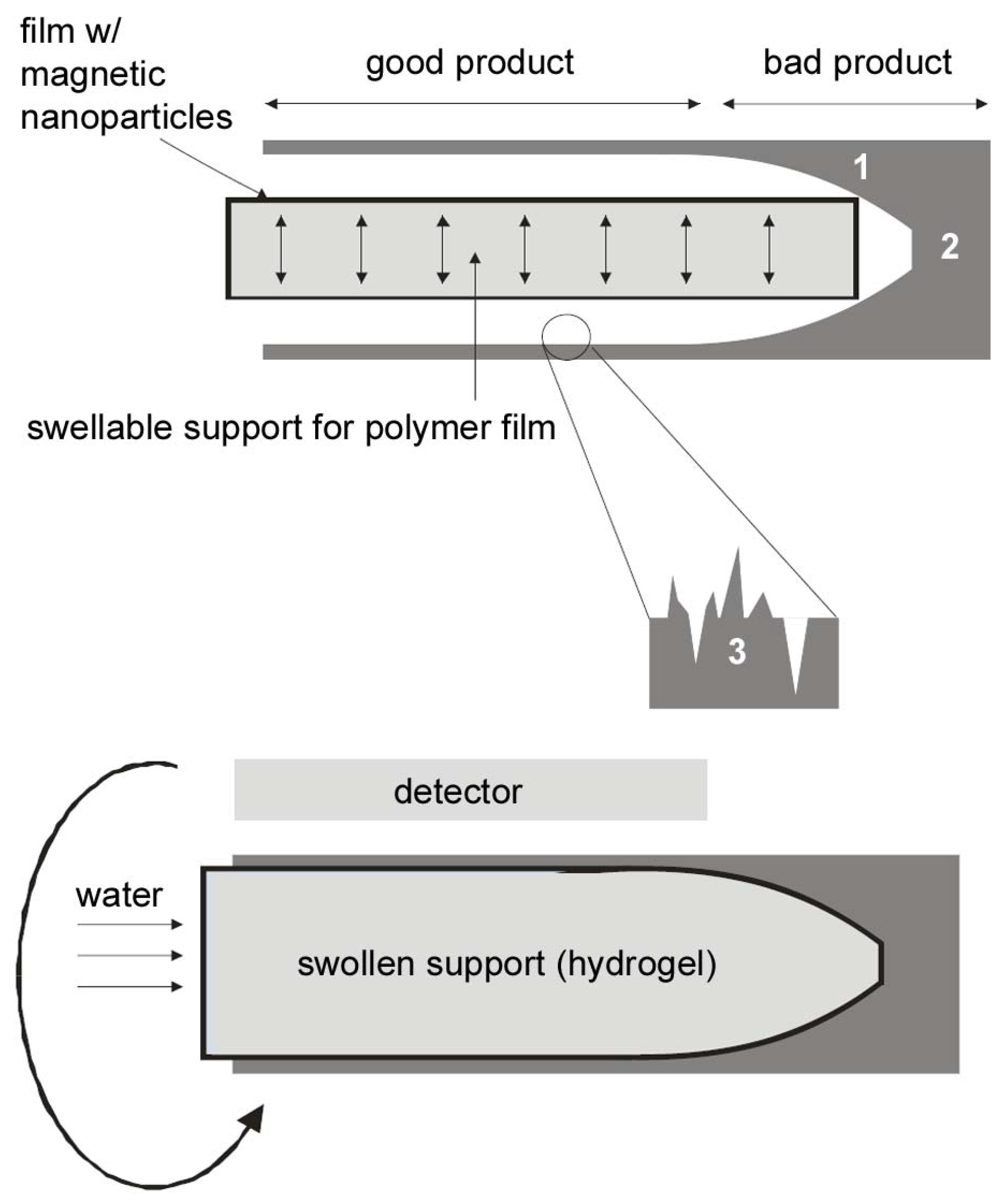
Hydrogels are used to provide inside pressure in the tube and push the polymer/MNP film to the tube walls. Several requirements need to be met: (i) the polymers need to swell fast to avoid time-consuming characterization procedures, (ii) the polymers need to swell uniformly to provide a uniform distribution of the MNPs on the inner tube walls, (iii) the polymers need to swell sufficiently to provide strong contact between the tube walls and the polymer film.
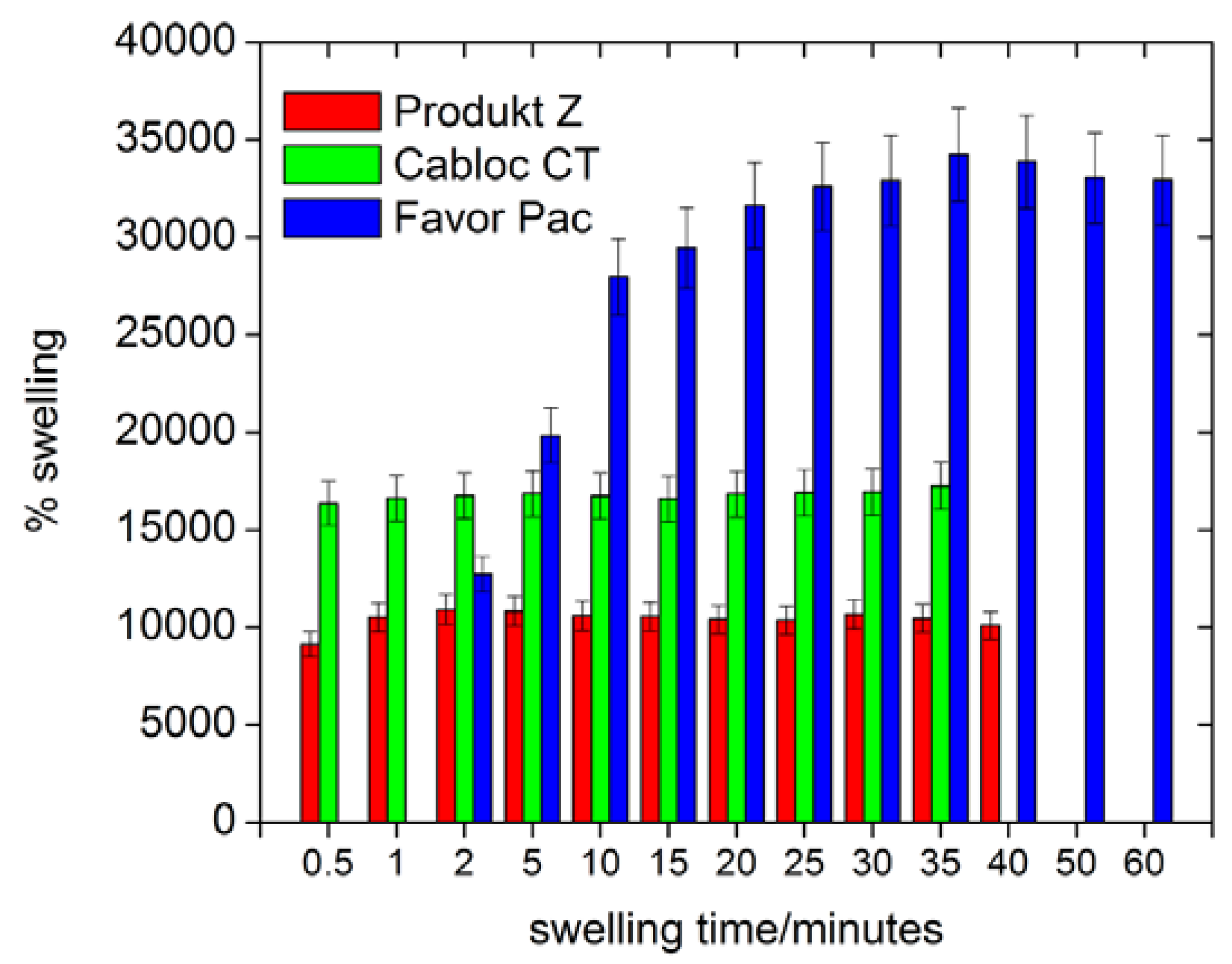
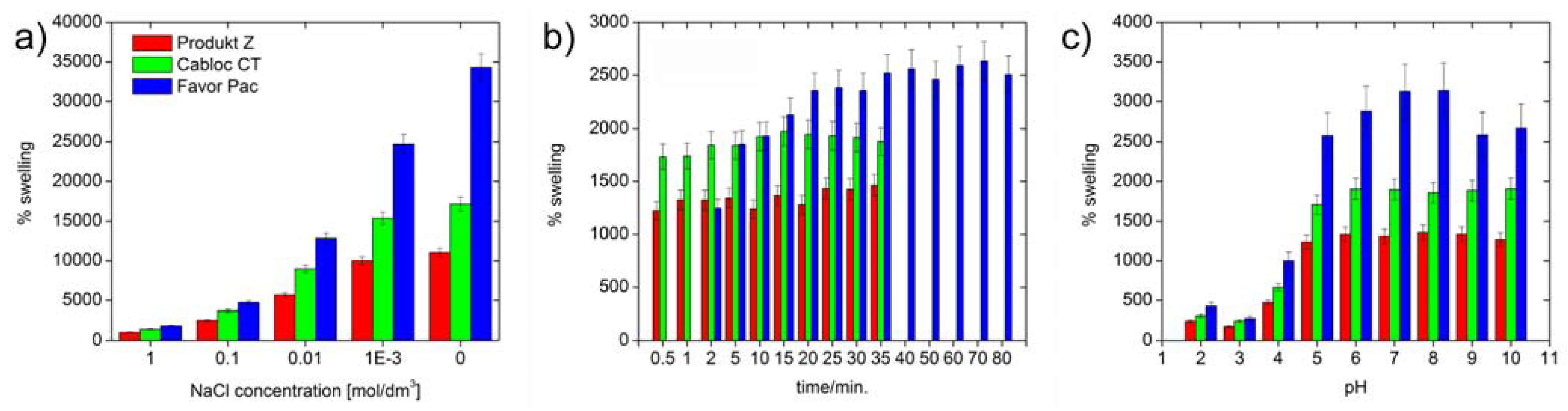
Figure 4 shows that all polymers swell by at least 8000 % in deionized water.
Figure 5 also shows that Produkt Z and Cabloc CT swell rather quickly and within a few minutes reach their final degrees of swelling. Favor pac 230 swells more, but requires ca. 30 minutes to reach the final degree of swelling.
Figure 4.
Swelling of the polymers in deionized water vs. time.
Figure 4.
Swelling of the polymers in deionized water vs. time.
Figure 5 shows that, not surprisingly, the swelling is strongly reduced with ionic strength, but the
rates of swelling are not affected by the ionic strength. As all polymers are crosslinked polyacids, their degrees of swelling at pH 5 and higher are roughly unchanged, but the hydrogels collapse at pH 4 and lower and a much weaker swelling is observed.
Figure 5.
Swelling of the three polymers in deionized water as a function of time: a) maximum degree of swelling vs. ionic strength, b) swelling rate for 0.5 M NaCl. Compare
Figure 4 for swelling in pure water, c) maximum swelling at different pH values.
Figure 5.
Swelling of the three polymers in deionized water as a function of time: a) maximum degree of swelling vs. ionic strength, b) swelling rate for 0.5 M NaCl. Compare
Figure 4 for swelling in pure water, c) maximum swelling at different pH values.
For the final device to function properly, complete filling of the tubes and a clean contact with the inner surface of the tubes is required. Bubbles and other defects are to be avoided.
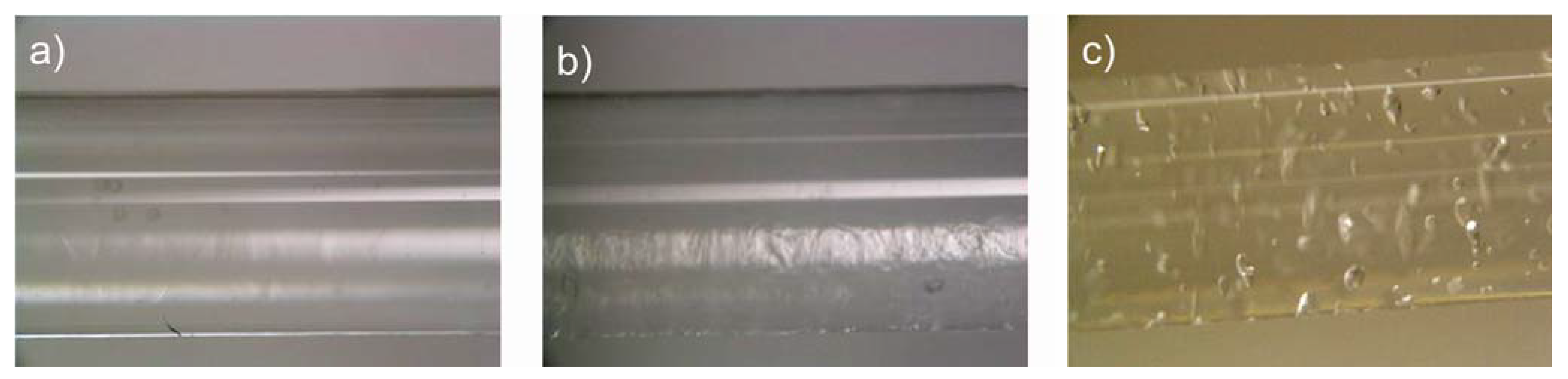
Figure 6 shows photographs of the three polymers in glass tubes with the same diameters as the final implants (2 mm). Cabloc CT completely fills the inner part of the capillary. Produkt Z also fills the capillary, but some contrast indicative of a residual roughness is observed here. Favor pac remains partially unswollen and has numerous cavities. As a result, Cabloc CT is most suited for the actuator and we have therefore focused on Cabloc CT for the remainder of the study.
Figure 6.
Representative photographs of hydrogels swollen in 2 mm diameter glass capillaries with deionized water. (a) Cabloc CT, (b) Produkt Z 1069, and (d) Favor pac 230. White lines on the tubes are reflections on the glass from the lamp used to illuminate the samples.
Figure 6.
Representative photographs of hydrogels swollen in 2 mm diameter glass capillaries with deionized water. (a) Cabloc CT, (b) Produkt Z 1069, and (d) Favor pac 230. White lines on the tubes are reflections on the glass from the lamp used to illuminate the samples.
2.4. Implementation of the device
As discussed above, film 10 (which has the same composition and properties as films 3 and 6) shows the best characteristics in terms of mechanical properties, homogeneity, and MNP loading. From the polymer hydrogels, Cabloc CT shows best filling characteristics. These two components were therefore chosen for a prototype of the final device.
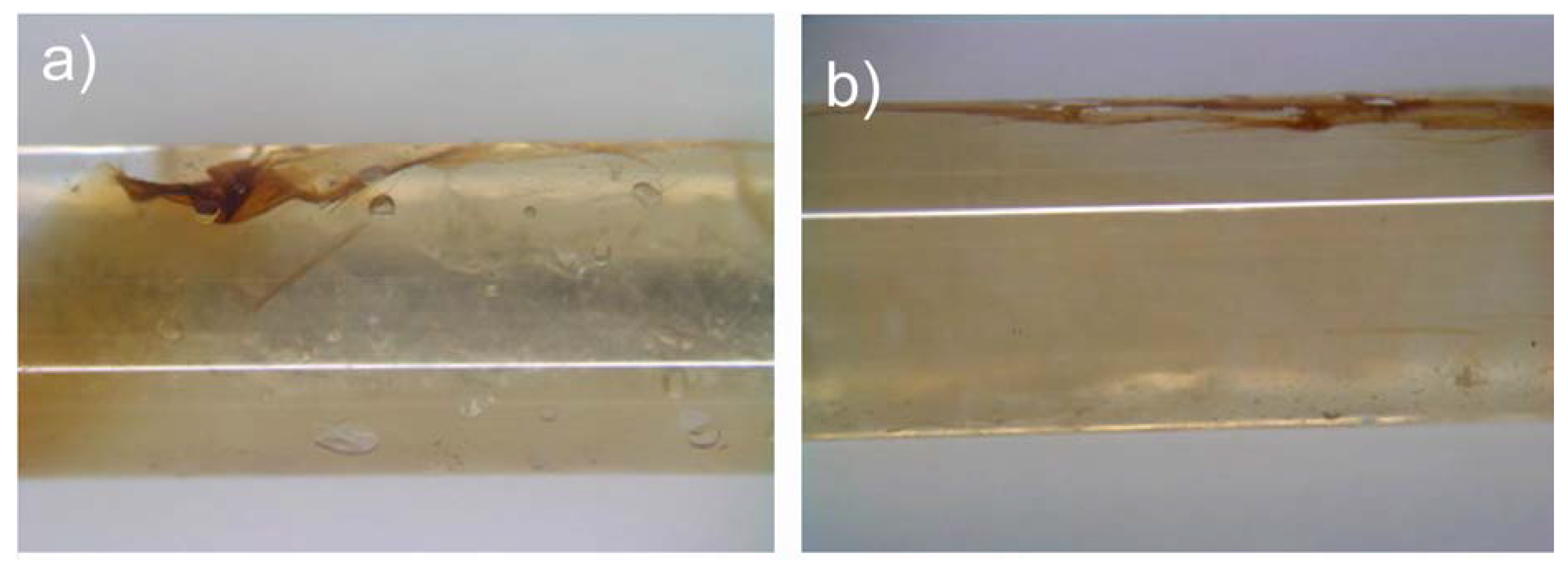
Figure 7 shows typical results, including the two most common defects. The film (brownish) inserted into the glass capillaries adheres well to the capillary walls. However, overlapping of the film can be also noticed, as well as some cavities between the wall and film due to lack of hydrogel at that particular place. As a result,
Figure 7 shows that the magnetic film can be introduced and pushed against the tube wall by the Cabloc CT filling.
Figure 7, however, also shows that the implementation is not perfect yet. There is a need for further optimization, in particular with respect to the film-tube contact and folding of the film.
Figure 7.
Photographs of the hybrid actuator assembled from films and swollen Cabloc CT hydrogels in a 2 mm diameter glass tube. There are two common defects: (a) the film adheres well to the inner surface but some parts of the film overlap. (b) At lower loading of hydrogel, there are bubbles between the wall and the film. Both structures will result in wrong reconstructions of the inner surface. White lines on the tubes are reflection on the glass from the lamp used to illuminate the samples.
In summary, the current study shows that our actuator is interesting for the analysis of tubular structures, but also that there is need for improvement. Approaches for improvement are (i) fabrication of more homogeneous films by using more controlled conditions such as spin coating or solution casting under better evaporation control, (ii) optimization of the MNP dispersion prior and during film formation, (iii) fabrication of preformed hydrogel components in a mold instead of using superabsorbent polymer powders, and (iv), on the longer run, a synthetic approach leading to a polymer hydrogel “monolith” where the magnetic film can be covalently attached to the surface as smooth film. Especially the last approach will help avoiding the effects observed in
Figure 7: if the MNP/polymer film is attached to the central hydrogel part (which has been molded into a certain shape), folding will be prevented. Finally, the swelling of the central hydrogel must be controlled more accurately in order to avoid bubbles.


