Highly Loaded Fe-MCM-41 Materials: Synthesis and Reducibility Studies


Abstract
:
1. Introduction
2. Experimental
2.1. Synthesis Procedures
2.1.1. Direct Synthesis: (Aqueous) Acid-Mediated Route
2.1.2. Direct Synthesis: The Hydroxide Precipitate Route
2.1.3. Post-synthesis Metal Incorporation: Incipient Wetness Impregnation (IWI)
2.2. Characterization of Fe-MCM-41
3. Results and Discussion
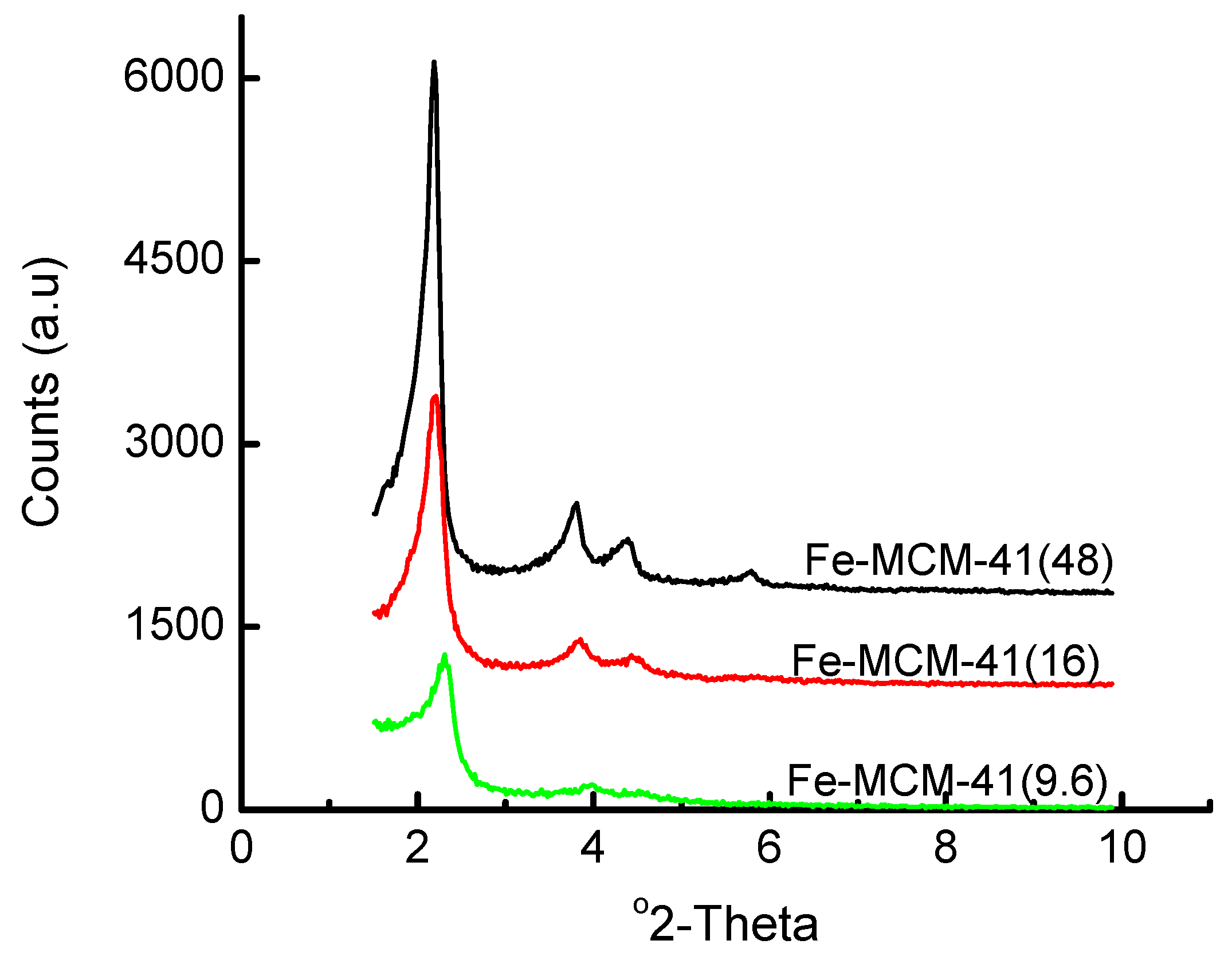
3.1. Acidified Aqueous Incorporation of Iron in MCM-41

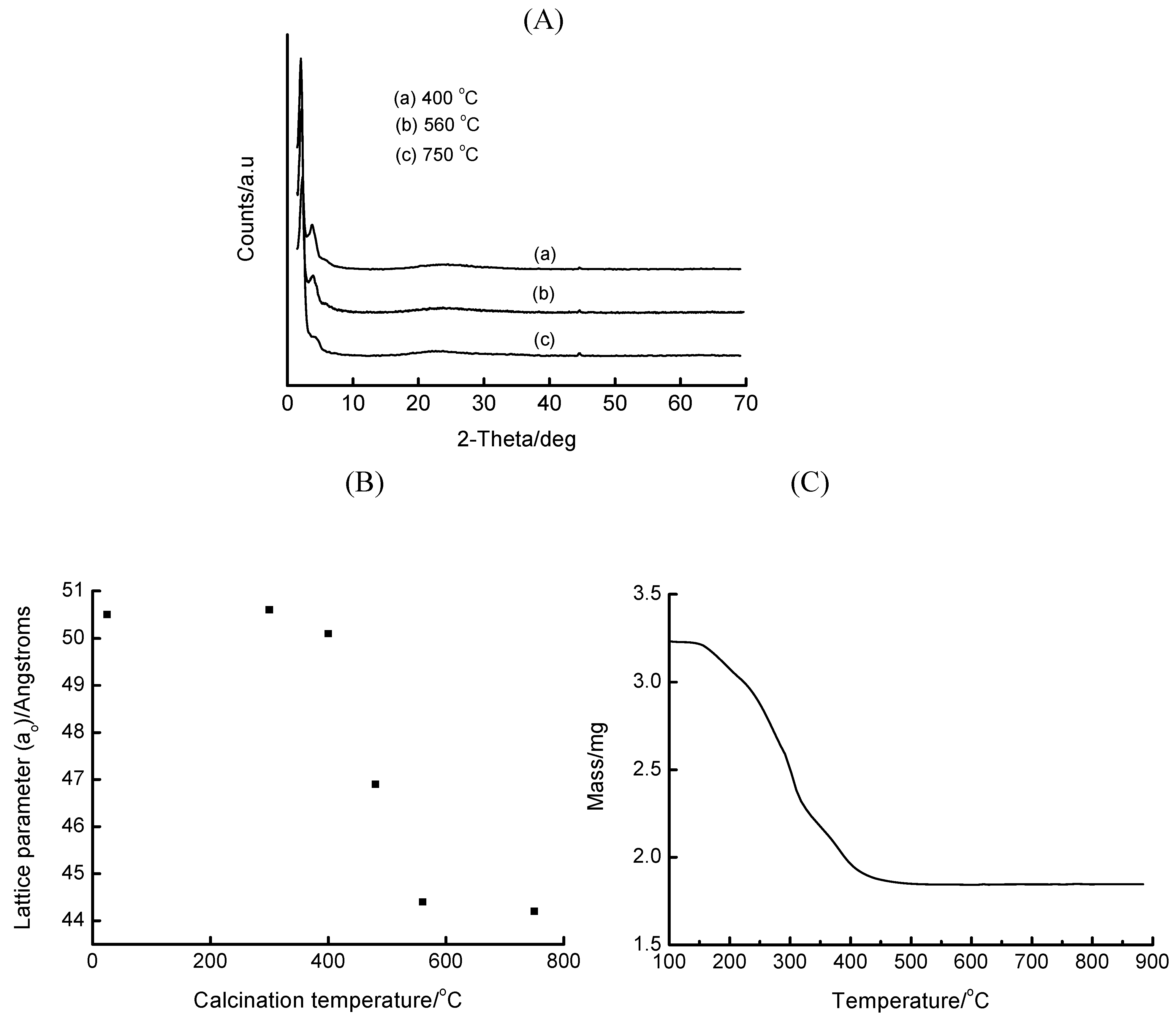
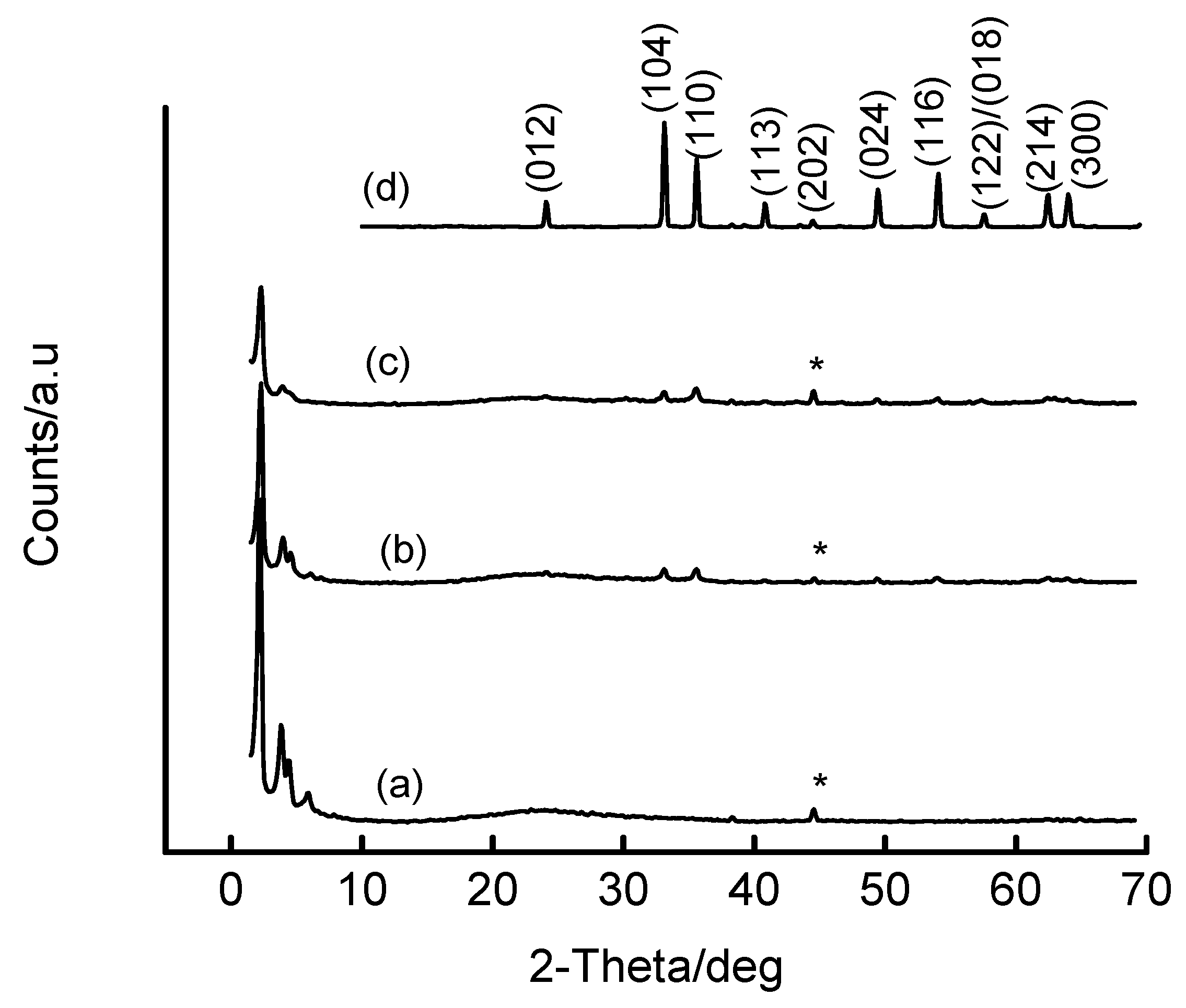
| Fe precursor mass/g | Gel Si/Fe ratio | Wt% Fe | ao/Å |
|---|---|---|---|
| 1.00 | 48 | ~2 | 46.6 |
| 3.00 | 16 | ~5 | 46.4 |
| 5.00 | 9.6 | ~8.8 | 44.1 |
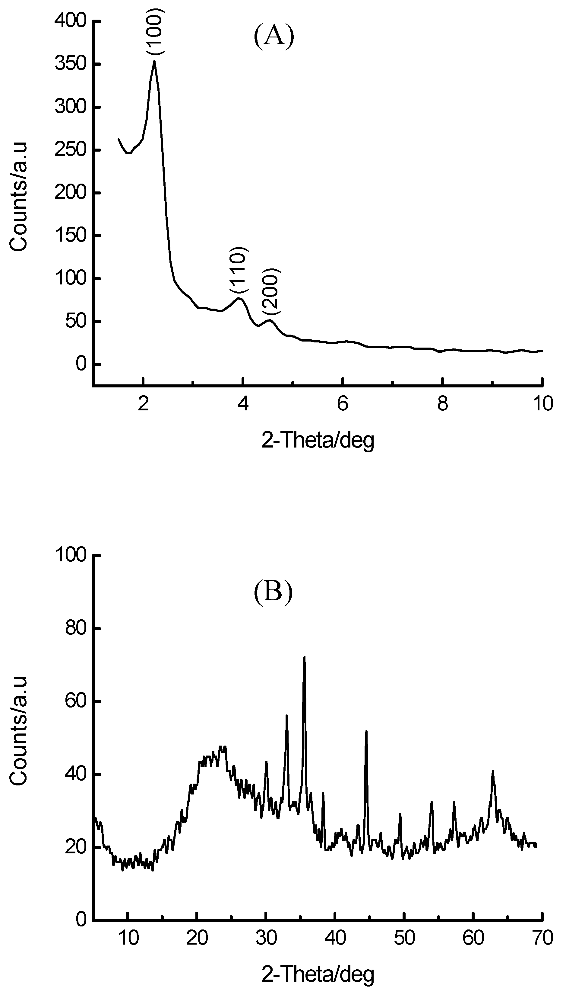
| 10.00 | 4.8 | ~16 | (100) not detected* |


3.2. Base-Mediated Incorporation of Iron in MCM-41

| Base | ao/Å | SBET/m2. g-1 |
|---|---|---|
| Na2CO3 | 44.9 | - |
| NaOH | 44.4 | 546 |
| N2H4.H2O | 46.1 | 617 |
| TMAOH* | 51.0 | 591 |
| (HOCH2CH2)3N | 42.0 | - |
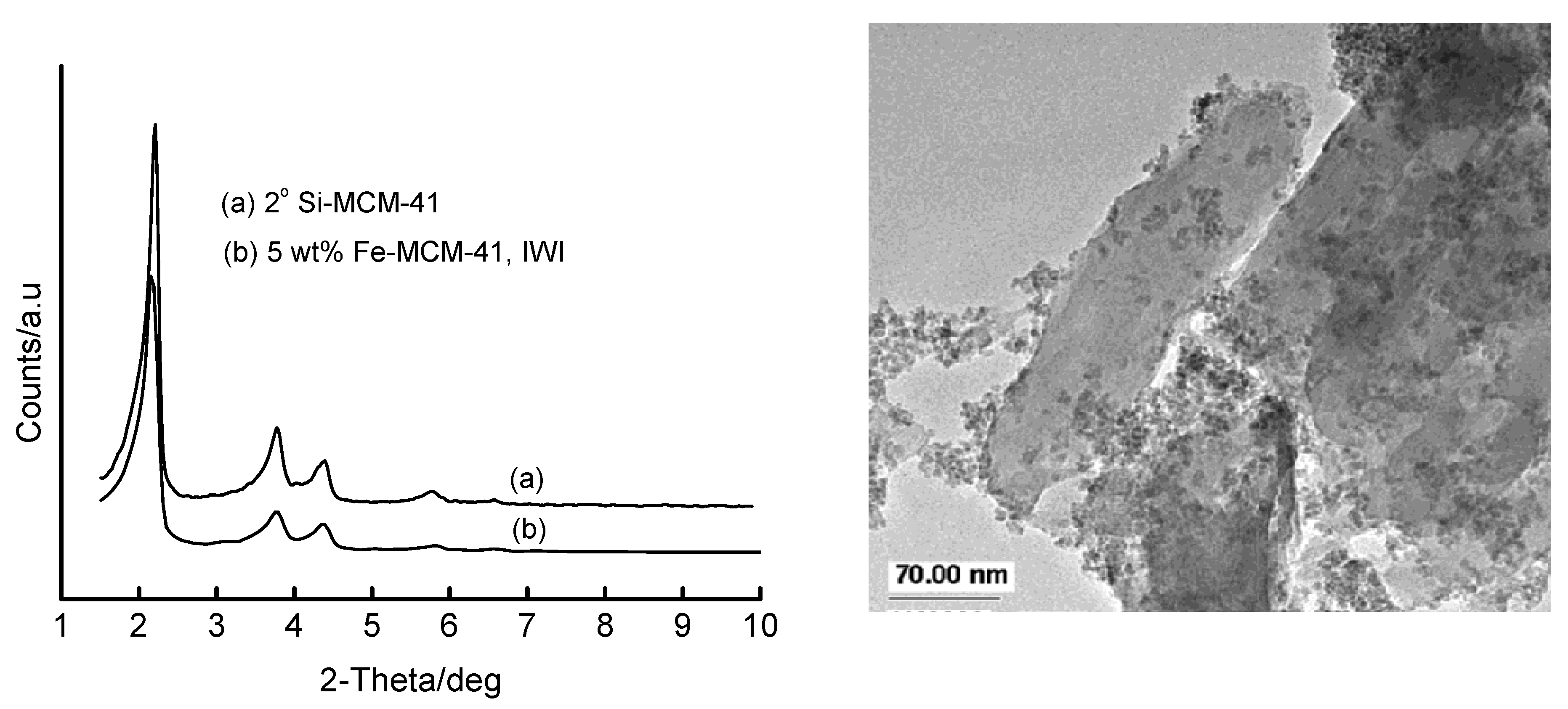
3.3. Incipient Wetness Impregnation (IWI) of Si-MCM-41 with Fe(III) Solutions

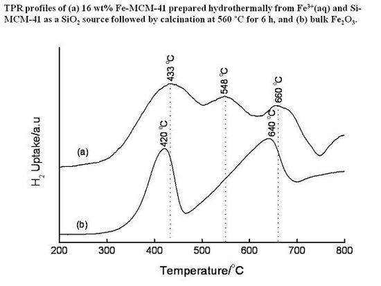
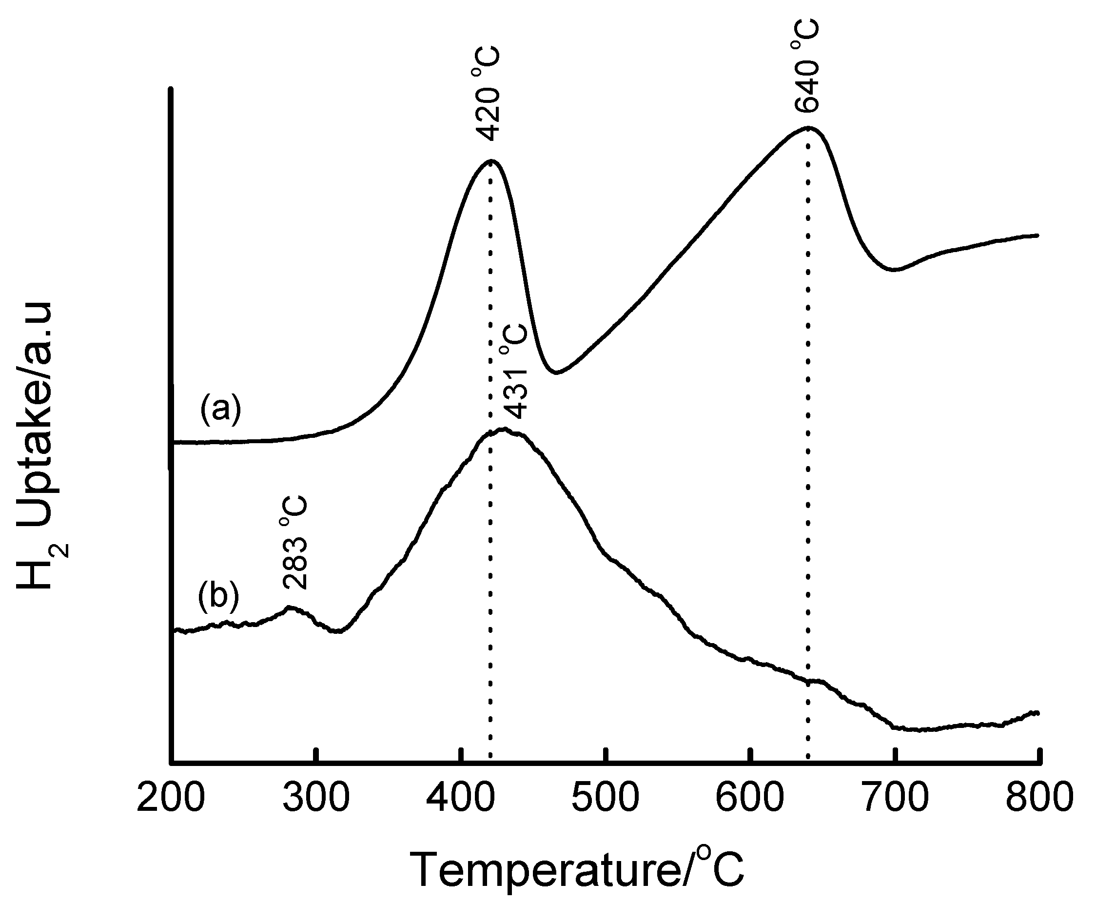
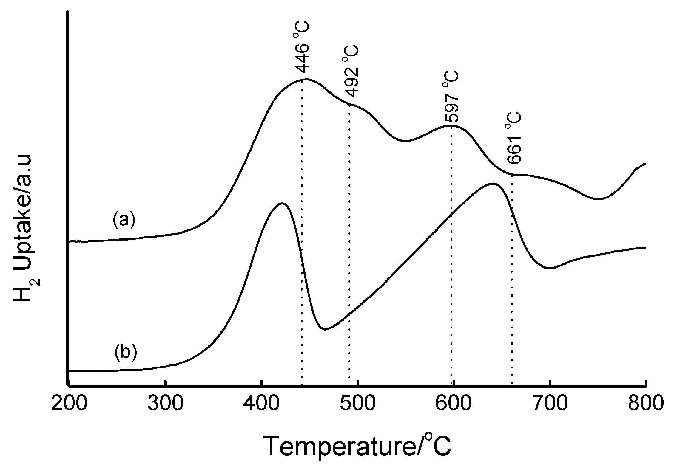
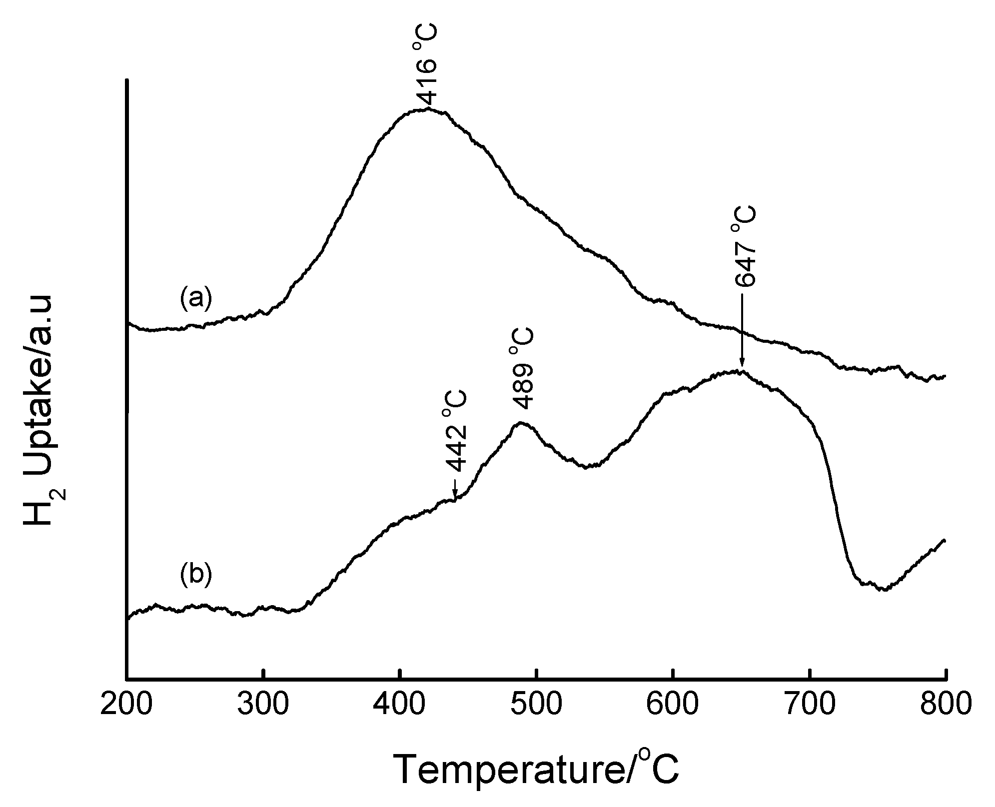
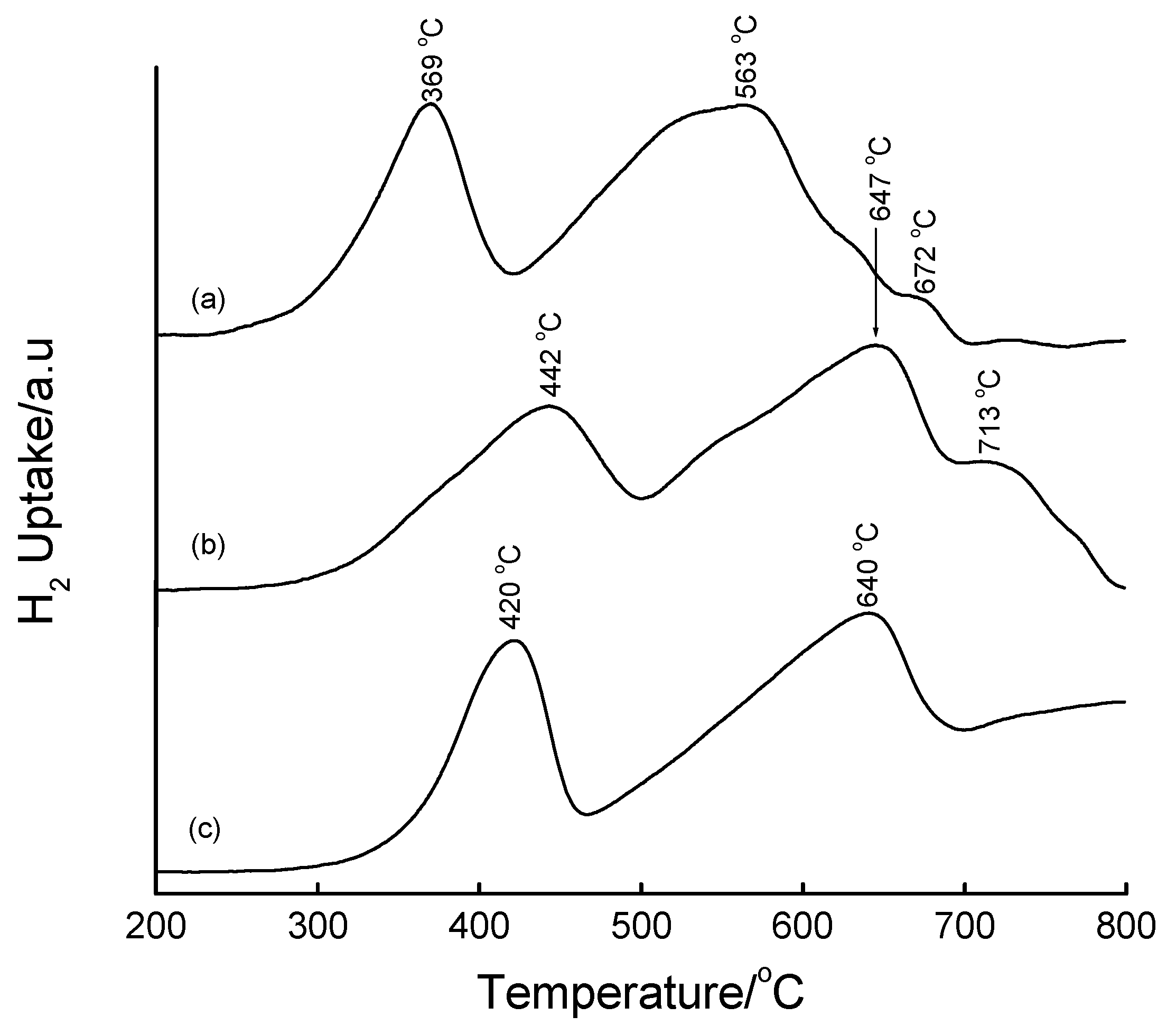
3.4. Temperature-Programmed Reduction (TPR) Studies

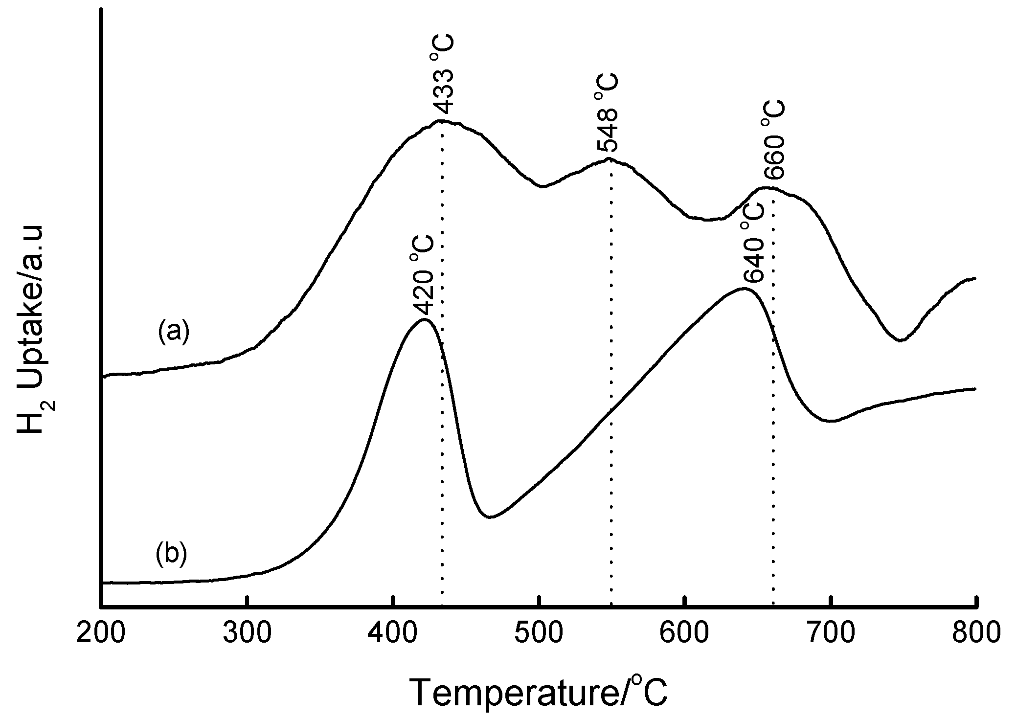
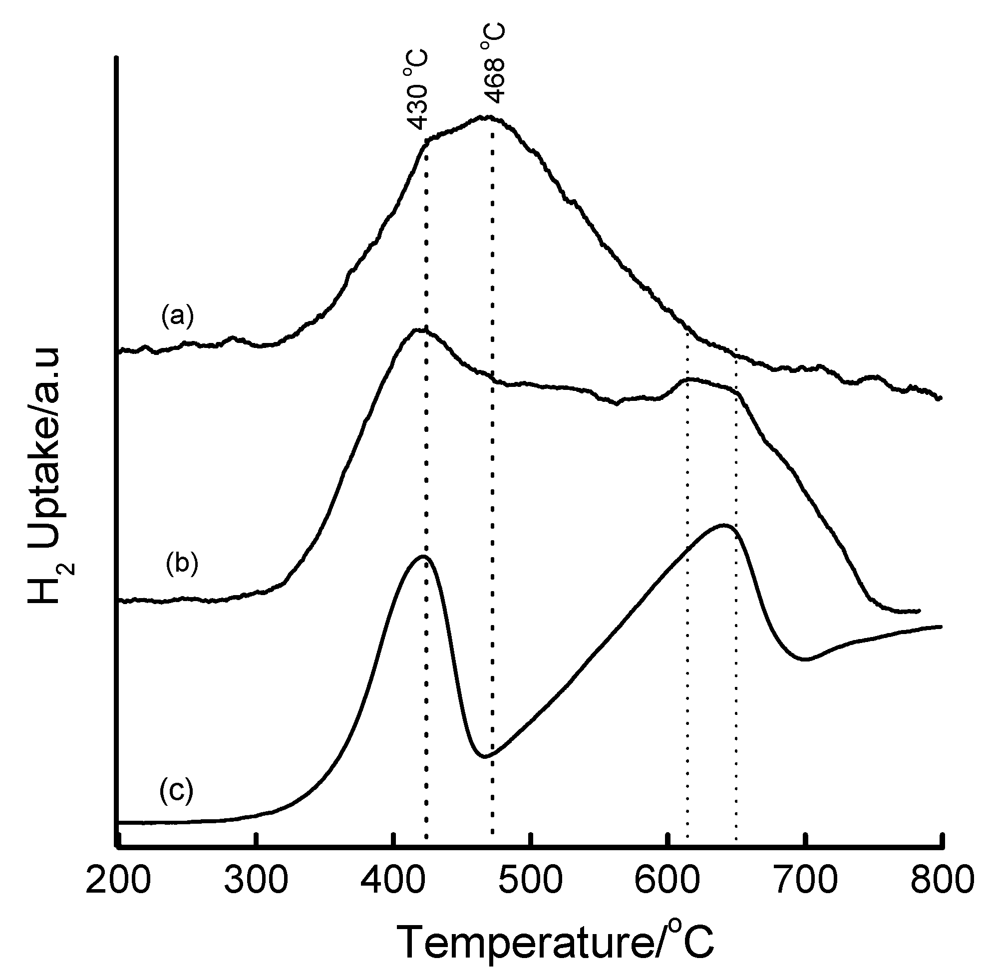


| Method | Loading/wt% | LT peak/°C | IT peak/°C | HT peak/°C |
|---|---|---|---|---|
| Bulk Fe2O3 | - | 420 | - | 640 |
| HDT/MSiO2 | 16 | 433 | 548 | 660 |
| IWI/2o MSiO2 | 5 | 387 | 497 | 661 |


4. Conclusions
Acknowledgements
Supplementary Materials
Supplementary materials can be downloaded online at https://www.mdpi.com/1996-1944/2/4/2337/s1/.References
- Szostak, R. Molecular Sieves: Principles of Synthesis and Identification; Van Nostrand Reinhold: New York, NY, USA, 1989; Chapter 8. [Google Scholar]
- De Vos, D.E.; Dams, M.; Sels, B.F.; Jacobs, P.A. Ordered Mesoporous and Microporous Molecular Sieves Functionalized with Transition Metal Complexes as Catalysts for Selective Organic Transformations. Chem. Rev. 2002, 102, 3615–3640. [Google Scholar]
- Corma, A.; Kan, Q. Synthesis of Si and Ti-Si-MCM-48 Mesoporous Materials with Controlled Pore Sizes in the Absence of Polar Organic Additives and Alkali Metal Ions. Chem. Commun. 1998, 579–580. [Google Scholar] [CrossRef]
- Jerrylaine, V.; Morey, M.; Carlsson, H.; Davidson, A.; Stucky, G.D.; Butler, A. Peroxidative Halogenation Catalyzed by Transition-Metal-Ion-Grafted Mesoporous Silicate Materials. J. Am. Chem. Soc. 1997, 119, 6921–6922. [Google Scholar] [CrossRef]
- Zhang, W.; Froba, M.; Wang, J.; Tanev, P.T.; Wong, J.; Pinnavaia, T.J. Mesoporous Titanosilicate Molecular Sieves Prepared at Ambient Temperature by Electrostatic (S+I-, S+X-I+) and Neutral (S°I°) Assembly Pathways: A Comparison of Physical Properties and Catalytic Activity for Peroxide Oxidations. J. Am. Chem. Soc. 1996, 118, 9164–9171. [Google Scholar] [CrossRef]
- Hagen, A.; Weingart, I.; Roessner, F.; Spliethoff, B. Synthesis of Iron-containing MFI type Zeolites and its Application to the Conversion of Ethane into Aromatic Compounds. Zeolites 1995, 15, 270–275. [Google Scholar] [CrossRef]
- Panov, G.I.; Uriarte, A.K.; Bodkin, M.A.; Sobolev, V.I. Generation of Active Oxygen Species on Solid Surfaces. Opportunity for Novel Oxidation Technologies over Zeolites. Catal. Today 1998, 41, 365–385. [Google Scholar] [CrossRef]
- Zhang, Q.; Guo, Q.; Wang, X.; Shishido, T.; Wang, Y. Iron-catalyzed Propylene Epoxidation by Nitrous Oxide: Toward Understanding the Nature of Active Iron Sites with Modified Fe-MFI and Fe-MCM-41 Catalysts. J. Catal. 2006, 239, 105–116. [Google Scholar] [CrossRef]
- Wang, Y.; Yang, W.; Yang, L.; Wang, X.; Zhang, Q. Iron-containing Heterogeneous Catalysts for Partial Oxidation of Methane and Epoxidation of Propylene. Catal. Today 2006, 117, 156–162. [Google Scholar] [CrossRef]
- Kapteijn, F.; Rodriguez-Mirasol, J.; Moulijn, J.A. Heterogeneous Catalytic Decomposition of Nitrous Oxide. Appl. Catal. B 1996, 9, 25–64. [Google Scholar] [CrossRef]
- Tian, Y.; Ogawa, E.; Ikuo, A.; Shishido, T.; Zhang, Q.; Wang, Y.; Takehira, K.; Hasegawa, S. Fe-MCM-41 for N2O Decomposition and Reduction with Methane. Chem. Lett. 2006, 35, 544–545. [Google Scholar] [CrossRef]
- Ko, J.R.; Ahn, W.S. Synthesis of Carbon Nanotubes Using Mesoporous Fe-MCM-41 Catalysts. J. Nanosci. Nanotechnol. 2006, 6, 3442–3445. [Google Scholar] [CrossRef] [PubMed]
- Barreca, D.; Blau, W.J.; Croke, G.M.; Deeney, F.A.; Dillon, F.C.; Holmes, J.D.; Kufazvinei, C.; Morris, M.A.; Spalding, T.R.; Tondello, E. Iron oxide Nanoparticle Impregnated Mesoporous Silicas as Platforms for the Growth of Carbon Nanotubes. Micropor. Mesopor. Mater. 2007, 103, 142–149. [Google Scholar] [CrossRef]
- Long, R.Q.; Yang, R.T. Superior Fe-ZSM-5 Catalyst for Selective Catalytic Reduction of Nitric Oxide by Ammonia. J. Am. Chem. Soc. 1999, 121, 5595–5596. [Google Scholar] [CrossRef]
- Mauvezin, M.; Delahay, G.; Kiesslich, F.; Coq, B.; Kieger, S. Catalytic Reduction of N2O by NH3 in Presence of Oxygen using Fe-exchanged Zeolites. Catal. Lett. 1999, 62, 41–44. [Google Scholar] [CrossRef]
- Traa, Y.; Burger, B.; Weitkamp, J. Zeolite-based Materials for the Selective Catalytic Reduction of NOx with Hydrocarbons. Micropor. Mesopor. Mater. 1999, 30, 3–41. [Google Scholar] [CrossRef]
- Kang, S.-H.; Bae, J.W.; Sai Prasad, P.S.; Jun, K.-W. Fischer-Tropsch Synthesis Using Zeolite-supported Iron Catalysts for the Production of Light Hydrocarbons. Catal. Lett. 2008, 125, 264–270. [Google Scholar] [CrossRef]
- Kang, S.-H.; Bae, J.W.; Sai Prasad, P.S.; Park, S.-J.; Woo, K.-J.; Jun, K.-W. Effect of Preparation Method of Fe–based Fischer–Tropsch Catalyst on Their Light Olefin Production. Catal. Lett. 2009, 130, 630–636. [Google Scholar] [CrossRef]
- Van Steen, E.; Claeys, M. Fischer-Tropsch Catalysts for the Biomass-to-Liquid (BTL) Process. Chem. Eng. Technol. 2008, 31, 655–666. [Google Scholar] [CrossRef]
- Martinez, A.; Prieto, G. The Application of Zeolites and Periodic Mesoporous Silicas in the Catalytic Conversion of Synthesis Gas. Top. Catal. 2009, 52, 75–90. [Google Scholar] [CrossRef]
- Dry, M.E. The Fischer-Tropsch synthesis. In Catalysis Science and Technology; Anderson, J.R., Boudart, M.E., Eds.; Springer: New York, NY, USA, 1981; Vol. 1, pp. 159–255. [Google Scholar]
- King, D.L.; Cusumano, J.A.; Garten, R.L. Technological Perspective for Catalytic Processes based on Synthesis Gas. Catal. Rev. 1981, 23, 233–263. [Google Scholar] [CrossRef]
- Saib, A.M.; Claeys, M.; van Steen, E. Silica Supported Cobalt Fischer-Tropsch Catalysts: Effect of Pore Diameter of Support. Catal. Today 2002, 71, 395–402. [Google Scholar] [CrossRef]
- Tang, Q.; Wang, P.; Zhang, Q.; Wang, Y. Utilization of Microporous and Mesoporous Materials as Supports of Cobalt Catalysts for Regulating Product Distributions in Fischer–Tropsch Synthesis. Chem. Lett. 2006, 35, 366–367. [Google Scholar] [CrossRef]
- Lira, E.; Lopez, C.M.; Oropeza, F.; Bartolini, M.; Alvarez, J.; Goldwasser, M.; Linares, F.L.; Lamonier, J.F.; Zurita, M.J.P. HMS Mesoporous Silica as Cobalt Support for the Fischer–Tropsch Synthesis: Pretreatment, Cobalt Loading and Particle Size Effects. J. Mol. Catal. A Chem. 2008, 281, 146–153. [Google Scholar] [CrossRef]
- Khodakov, A.Y.; Griboval-Constant, A.; Bechara, R.; Zholobenko, V.L. Pore Size Effects in Fischer Tropsch Synthesis over Cobalt-Supported Mesoporous Silicas. J. Catal. 2002, 206, 230–241. [Google Scholar] [CrossRef]
- Polvinen, R.; Vippola, M.; Valden, M.; Lepisto, T.; Suopanki, A.; Harkonen, M. The Effect of Platinum on the Reducibility of Rh oxides on Ce-Zr modified Alumina supported Automotive Catalysts. Surf. Interface Anal. 2004, 36, 741–744. [Google Scholar] [CrossRef]
- Chang, F.-W.; Kuo, M.-S.; Tsay, M.-T.; Hsieh, M.-C. Effect of Calcination Temperature on Catalyst Reducibility and Hydrogenation Reactivity in Rice Husk Ash-Alumina supported Nickel Systems. J. Chem. Technol. Biotechnol. 2004, 79, 691–699. [Google Scholar] [CrossRef]
- Chang, F.-W.; Tsay, M.-T.; Kuo, M.-S. Effect of Thermal Treatments on Catalyst Reducibility and Activity in Nickel Supported on RHA-Al2O3 Systems. Thermochim. Acta 2002, 386, 161–172. [Google Scholar] [CrossRef]
- Natesakhawat, S.; Oktar, O.; Ozkan, U.S. Effect of Lanthanide Promotion on Catalytic Performance of Sol-Gel Ni/Al2O3 Catalysts in Steam Reforming of Propane. J. Mol. Catal. A Chem. 2005, 241, 133–146. [Google Scholar] [CrossRef]
- Parmaliana, A.; Arena, F.; Frusteri, F.; Giordano, N. Temperature-Programmed Reduction study of NiO-MgO interactions in Magnesia-Supported Ni Catalysts and NiO–MgO Physical Mixture. J. Chem. Soc., Faraday Trans. 1990, 86, 2663–2669. [Google Scholar] [CrossRef]
- Yuan, Z.Y.; Lui, S.H.; Chen, T.H.; Wang, J.Z.; Li, H.X. Synthesis of Iron-containing MCM-41. J. Chem. Soc., Chem. Commun. 1995, 973–974. [Google Scholar]
- He, N.-Y.; Bao, S.-L.; Xu, Q.-H. Synthesis and Characterization of FeSiMCM-41 and LaSiMCM-41. Stud. Surf. Sci. Catal. 1997, 105, 85–92. [Google Scholar]
- Tuel, A.; Arcon, I.; Millet, J.M.M. Investigation of Structural Iron species in Fe-Mesoporous Silicas by Spectroscopic Techniques. J. Chem. Soc., Faraday Trans. 1998, 94, 3501–3510. [Google Scholar] [CrossRef]
- Shishido, T.; Zhang, Q.; Wang, Y.; Tanaka, T.; Takehira, K. XAFS Study on Active Iron Sites in MCM-41 as a Catalyst for Liquid Phase Oxidation. Physica Scripta 2005, T115, 762–764. [Google Scholar] [CrossRef]
- Samanta, S.; Giri, S.; Sastry, P.U.; Mal, N.K.; Manna, A.; Bhaumik, A. Synthesis and Characterization of Iron-Rich Highly Ordered Mesoporous Fe-MCM-41. Ind. Eng. Chem. Res. 2003, 42, 3012–3018. [Google Scholar] [CrossRef]
- Lin, H.P.; Cheng, S.; Mou, C.Y. Effect of Delayed Neutralization on the Synthesis of Mesoporous MCM-41 Molecular Sieves. Micropor. Mater. 1997, 10, 111–121. [Google Scholar] [CrossRef]
- Thitsartarn, W.; Gulari, E.; Wongkasemjit, S. Synthesis of Fe-MCM-41 from Silatrane and FeCl3 via Sol-gel Process and its Epoxidation Activity. Appl. Organomet. Chem. 2008, 22, 97–103. [Google Scholar] [CrossRef]
- Goldfarb, D.; Bernardo, M.; Strohmaier, K.G.; Vaughan, D.E.W.; Thomann, H. Characterization of Iron in Zeolites by X-band and Q-Band ESR, Pulsed ESR, and UV-Visible Spectroscopies. J. Am. Chem. Soc. 1994, 116, 6344–6353. [Google Scholar] [CrossRef]
- Wang, Y.; Zhang, Q.; Shishido, T.; Takehira, K. Characterizations of Iron-containing MCM-41 and its Catalytic properties in Epoxidation of Styrene with Hydrogen Peroxide. J. Catal. 2002, 209, 186–196. [Google Scholar]
- Perez-Ramirez, J.; Mul, G.; Kapteijn, F.; Overweg, A.R.; Domenech, A.; Ribera, A.; Arends, I.W.C.E. Physicochemical Characterization of Isomorphously Substituted FeZSM-5 during Activation. J. Catal. 2002, 207, 113–126. [Google Scholar] [CrossRef]
- Mokaya, R. Improving the Stability of Mesoporous MCM-41 Silica via Thicker More Highly Condensed Pore Walls. J. Phys. Chem. B 1999, 103, 10204–10208. [Google Scholar] [CrossRef]
- Pena, J.A.; Lorente, E.; Romero, E.; Herguido, J. Kinetic Study of the Redox Process for Storing Hydrogen: Reduction Stage. Catal. Today 2006, 116, 439–444. [Google Scholar] [CrossRef]
- Hayashi, H.; Kishida, M.; Wakabayashi, K. Metal-Support Interaction and Catalysis of the Catalysts Prepared using Microemulsion. Catal. Surv. Jpn. 2002, 6, 9–17. [Google Scholar] [CrossRef]
- Chen, K.; Yan, Q. CO Hydrogenation over Zirconia Supported Iron Catalysts Promoted with Rare Earth Oxides. Appl. Catal. A Gen. 1997, 158, 215–223. [Google Scholar] [CrossRef]
- Nesterenko, N.S.; Ponomoreva, O.A.; Yuschenko, V.V.; Ivanova, I.I.; Testa, F.; Di Renzo, F.; Fajula, F. Dehydrogenation of Ethylbenzene and Isobutane over Ga- and Fe-containing Mesoporous Silicas. Appl. Catal. A: Gen. 2003, 254, 261–272. [Google Scholar] [CrossRef]
- Gao, Z.; Zhang, B.; Cui, J. Activity of Highly Dispersed α-Fe2O3 on Molecular Sieves for Ethylbenzene Dehydrogenation. Appl. Catal. 1991, 72, 331–342. [Google Scholar] [CrossRef]
- Pineau, A.; Kanari, N.; Gaballah, I. Kinetics of Reduction of Iron oxides by H2: Part I: Low Temperature Reduction of Hematite. Thermochim. Acta 2006, 447, 89–100. [Google Scholar] [CrossRef]
- Jozwiak, W.K.; Kaczmarek, E.; Maniecki, T.P.; Ignaczak, W.; Maniukiewicz, W. Reduction behavior of Iron oxides in Hydrogen and Carbon Monoxide Atmospheres. Appl. Catal. A: Gen. 2007, 326, 17–27. [Google Scholar] [CrossRef]
- Rojas, S.; Perez-Alonso, F.J.; Ojeda, M.; Terreros, P.; Fierro, J.L. Carbon oxide Hydrogenation over Silica-supported iron-based Catalysts: Influence of the Preparation Route. Appl. Catal. A: Gen. 2006, 308, 19–30. [Google Scholar] [CrossRef]
- Szegedi, A.; Pal-Borbely, G.; Lazar, K. Comparison of the Redox Properties of Iron Incorporated in Different Amounts into MCM-41. React. Kinet. Catal. Lett. 2001, 74, 277–287. [Google Scholar] [CrossRef]
- Szegedi, A.; Kόnya, Z.; Méhn, D.; Solymár, E.; Pál-Borbély, G.; Horváth, Z.E.; Birό, L.P.; Kiricsi, I. Spherical Mesoporous MCM-41 Materials containing Transition Metals: Synthesis and Characterization. Appl. Catal. A: Gen. 2004, 272, 257–266. [Google Scholar] [CrossRef]
- Afzal, M.; Theocharis, C.R.; Karim, S. Temperature Programmed Reduction of Silica Supported Nickel Catalysts. Colloid Polym. Sci. 1993, 271, 1100–1105. [Google Scholar] [CrossRef]
© 2009 by the authors; licensee Molecular Diversity Preservation International, Basel, Switzerland. This article is an open-access article distributed under the terms and conditions of the Creative Commons Attribution license (http://creativecommons.org/licenses/by/3.0/).
Share and Cite
Mokhonoana, M.P.; Coville, N.J. Highly Loaded Fe-MCM-41 Materials: Synthesis and Reducibility Studies. Materials 2009, 2, 2337-2359. https://doi.org/10.3390/ma2042337
Mokhonoana MP, Coville NJ. Highly Loaded Fe-MCM-41 Materials: Synthesis and Reducibility Studies. Materials. 2009; 2(4):2337-2359. https://doi.org/10.3390/ma2042337
Chicago/Turabian StyleMokhonoana, Malose P., and Neil J. Coville. 2009. "Highly Loaded Fe-MCM-41 Materials: Synthesis and Reducibility Studies" Materials 2, no. 4: 2337-2359. https://doi.org/10.3390/ma2042337