Synthesis Methods of Carbon Nanotubes and Related Materials

Abstract
:1. Introduction
2. Synthesis Methods
3. Arc Discharge Method

| Method | Product | Comments | Conditions | References |
|---|---|---|---|---|
| Plasma rotating | CNTs | Large scale | Pure graphite electrodes, He | [37] |
| Arc discharge | CNTs | Deionized water | [32] | |
| MWNTs, carbon onions | [31] | |||
| CNTs | Metal filled | [30] | ||
| MWNTs, SWNTs, carbon nanocapsules | NaCl solution | [29] | ||
| MWNTs, multishell carbon onions | Distorted morphology, irregular shape | Liquid environments | [28] | |
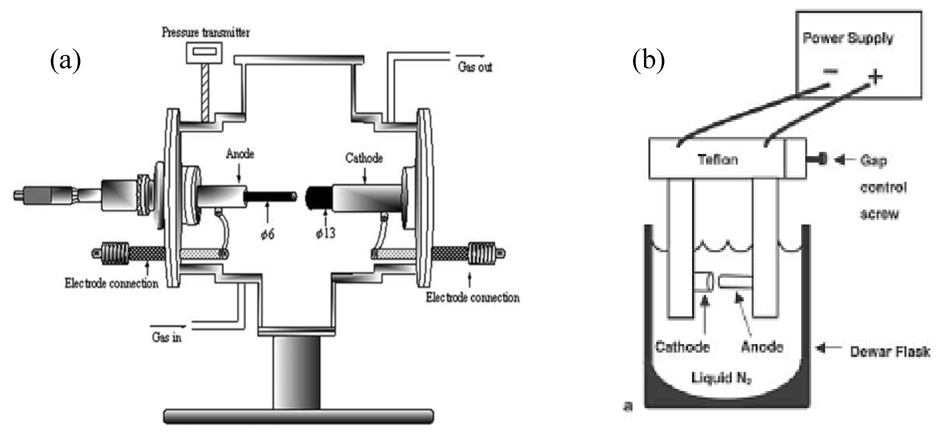
| Arc discharge | SWNTs, nanohorns | Liquid N2 | [27] | |
| Spheroidal nanocarbons, graphite sheets, tube-like nanocarbons | Toluene, different types of catalysts | [25] | ||
| Arc discharge | CNTs | Continuous production | [26] | |
| SWNTs, fullerenes, metallofullerenes | d = 0.9–1.4 nm | Y/Ni and CaC2/Ni catalyst, He | [23] | |
| SWNT fibers | High purity | [19] | ||
| SWNTs, CNT ribbons | High yield | Ho/Ni catalyst | [18] | |
| MWNTs, sheet like structures, spherical particles, beaded CNTs | The product type depends on the catalyst composition | PVA, PVA/Fe catalysts, various Fe sources | [17] | |
| Arc discharge | DWNTs | Large quantity, high quality, d = 2–6 nm | KCl/FeS catalyst, H2 | [24] |
| Mixture of Ni/Co/Fe small amount of S, Ar:H2 | [20] | |||
| FeS, CoS, NiS catalysts, H2 | [21] | |||
| Bundles of high quality | [22] | |||
| MWNTs | Optimization process | Graphite electrodes, H2 | [35] | |
| Pulsed arc | CNTs, onion-like particles | Straight with d = 20 nm, aggregations of nano-onions d = 15–20 nm | Pure graphite rods, deionized water | [36] |
| AC-Arc discharge | MWNTs, nano-onions | Well graphitized, closed ends, nano-onions d = 20–50 nm | Deionized water, various carbon sources and catalysts | [33,34] |
3.1. Catalyst composition and carbon sources


3.2. The reaction environments
3.3. The pressure of gases
3.4. Types of arc discharge methods
4. Laser Ablation Method

4.1. Target composition
4.2. Carrier gas parameters


4.3. The effect of laser parameters and furnace temperature

| Method | Product | Conditions | References |
|---|---|---|---|
| XeCl excimer | SWNT bundles, fullerenes | Process temperature: 1000–1350 °C; C/Ni/Co; Ar | [65] |
| KrF excimer | MWNTs, nano-onions | Target composition: C/Ni, C/Ni/Co; gas nature: Ar, O2; room T | [60] |
| CO2 continuous wave | SWNT bundles, bamboo-like structures | Laser power: 400–900 W; C/Ni/Co, room T Ar: 200–400 Torr; | [55] |
| Pulsed Nd:YAG | SWNT bundles | Laser intensity: 532 nm, 1064 nm, double beam 532 and 1064 nm; C/Ni/Co; Ar; Furnace T: 800–1150 °C | [50] |
| CO2 continuous wave | Gas-powder suspension catalyst; Ar, N2; 1100 °C | [59] | |
| Gas nature Ar, He, N2 50–500 Torr; C/Ni/Y | [61] | ||
| CO2 continuous and pulsed wave | SWNTs | Catalyst composition, gas conditions: Ar, He, N2 50–500 Torr, laser power density: 12–9-6 kW/cm2 | [58] |
| Configuration of laser wave | [64] | ||
| Effect of the growth temperature | [52] | ||
| Pulsed Nd:YAG laser | Thin SWNTs | Target composition, reaction T and gas flow velocity | [46] |
| CO2 pulsed laser | SWNTs | Target composition | [56] |
| Gas nature and its pressure | [57] | ||
| CO2 continuous wave | CNTs | Effect of furnace temperature | [51] |
| Pulsed double beam Nd:YAG | SWNTs | Effect of the laser intensity | [41] |
| Pulsed Nd:YAG | [42] | ||
| KrF excimer | Furnace T = 550 °C | [49] | |
| Pulsed Nd:YAG | Laser parameters | [53,54] | |
| Target composition | [44,45] | ||
| Pulsed double beam Nd:YAG | Gas pressure, flow | [47,48] | |
| KrF excimer UV laser | SWNT bundles | Furnace temperature 25–1150 °C; Ar, C/Ni/Co | [66] |
| CO2 laser | Carbon nanohorns | Gas nature Ar, Ne, He; Pure C | [62] |
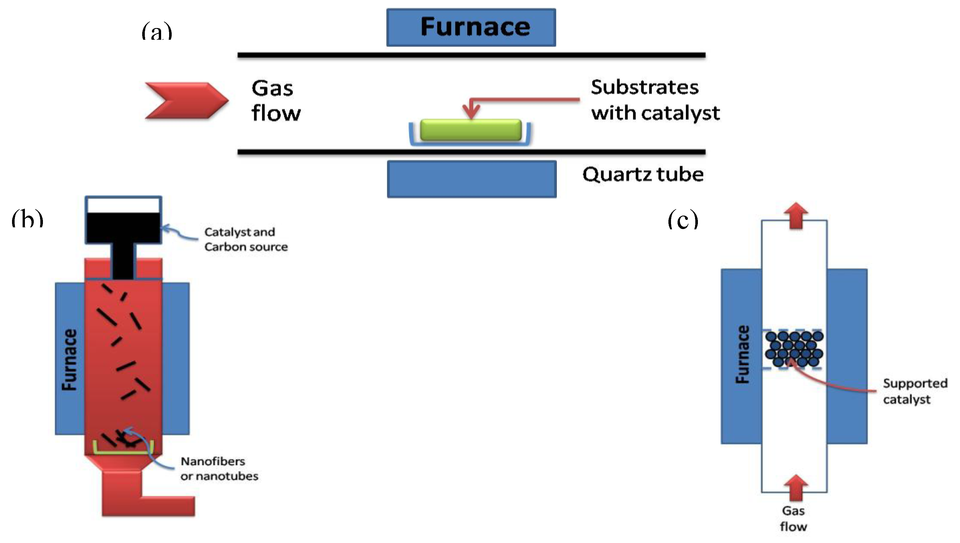
5. Chemical Vapour Deposition Method
| Method | Product | Characteristics | C source, catalyst | References |
|---|---|---|---|---|
| Water-assisted | Vertically aligned SWNTs, DWNTs | High yield | With buffer layer | [128] |
| O2-assisted plasma-enhanced | [129] | |||
| Microwave plasma-enhanced | [130] | |||
| Microwave plasma-enhanced | Verticaly aligned SWNTs | Co-Ti/Si substrate without a buffer layer | [131] | |
| Simple CVD | Carbon spheres | Ball-like, chain-like morphology | Toluene, without catalyst | [144] |
| Filled CNTs, Fe3C nanowires | Acetylene, titanate modified palygorskite | [165] | ||
| Regularly coiled carbon fibers | Large scale | Acetylene, small amount of S or P | [148] | |
| Hot wire CVD | 3D double-helix microcoils | Amorphous structure | Methane, Ni catalyst | [147] |
| DC-PECVD | Carbon fibres | [146] | ||
| Microwave plasma-enhanced | Carbon nanofibres | Vertically aligned | Catalyst free, CO/Ar/O2, low temperature | [145] |
| Hot filament-enhanced | SWNTs, MWNTs | Perpendicularly or vertically aligned | Fe-Co/SiO2 with or without of Si support | [127] |
| Alcohol CVD | CNTs | Multibranched morphology | Cu/MgO | [142,143] |
| High power laser pulse alcohol CVD | SWNTs | Solid metal target | [135] | |
| Alcohol CVD | High purity | Ferrocene-ethanol | [89,132,133,134] | |
| Thermal CVD | CNTs | Aligned | Co/SiO2, Ar/H2 and NH3/N2 | [140,141] |
| Simple CVD | SWNTs | Individual and in bundles | Fe-Mo/Si substrate, methane | [139] |
| Microwave plasma-enhanced | CNTs | Well aligned, curved with random orientation | Fe/sapphire, Ni-Fe/glass, Cr-Fe/glass, Fe/Si, stainless steal | [126] |
| Injection CVD | MWNT films | Aligned, encapsulated nanoparticles | Quartz substrate, ferrocene/toluene | [125] |
| MWNTs | Mainly straight, some thick CNTs | Different carbon sources and metal catalyst | [33] | |
| CVD | CNTs, carbon onions | Ni/Al | [120,121] | |
| Metal filled, bamboo shaped | Ni/Cu/Al, methane | [122,123] | ||
| MWNTs | K-doped Co and Co-Fe/zeolite and CaCO3 | [114] | ||
| SWNTs, DWNTs | Fe-Mo/MgO | [110,111,112,113] | ||
| CNTs | Different metals and rare-earth promoters | [109] | ||
| CVD | Aligned CNTs | Single-crystal of sapphire or quartz | [83,84,85] | |
| CNTs, graphite layers, filaments | Different types of catalysts | [73,74,75,76] | ||
| Helicoidal CNTs | Regular and irregular shape | [152,159,160] | ||
| Alcohol CCVD | CNTs | Various morphology depending on the metal film thickness | Co/Si, Co-Mo/Si, Co/quartz, Co-Mo/quartz | [136,137] |
| Ultrasonic spray pyrolysis | SWNTs | d = 0.8–1.2 nm | Co-Mo/silicon substrate, ethanol | [138] |
5.1. Carbon source and inert gas
5.2. Catalyst and support materials
5.3. The substrate


5.4. Gas phase metal catalyst

5.5. Different types of CVD

5.6. Different kinds of carbonaceous materials


6. Hydrothermal Synthesis
7. Electrolysis
8. Solar Technique
9. Conclusions
References and Notes
- Iijima, S. Helical microtubules of graphitic carbon. Nature 1991, 354, 56–58. [Google Scholar] [CrossRef]
- Radushkevich, L.V.; Lukyanovich, V.M. O strukture ugleroda, obrazujucegosja pri termiceskom razlozenii okisi ugleroda na zeleznom kontakte. Zurn. Fisic. Chim. 1952, 26, 88–95. [Google Scholar]
- Oberlin, A.; Endo, M.; Koyama, T. Filamentous growth of carbon through benzene decomposition. J. Cryst. Growth 1976, 32, 335–349. [Google Scholar] [CrossRef]
- Amelinckx, S.; Zhang, X.B.; Bernaerts, D.; Zhang, X.F.; Ivanov, V.; B.Nagy, J. A formation mechanism for catalytically grown helix-shaped graphite nanotubes. Science 1994, 265, 635–639. [Google Scholar] [CrossRef] [PubMed]
- B.Nagy, J.; Bister, G.; Fonseca, A.; Méhn, D.; Kónya, Z.; Kiricsi, I.; Horváth, Z.E.; Biró, L.P. On the growth mechanism of single-walled carbon nanotubes by catalytic carbon vapor deposition on supported metal catalysts. J. Nanosci. Nanotech. 2004, 4, 326–345. [Google Scholar] [CrossRef]
- Harris, P.J.F. Solid state growth mechanism for carbon nanotubes. Carbon 2007, 45, 229–239. [Google Scholar] [CrossRef]
- Popov, V.N. Carbon nanotubes: Properties and application. Mat. Sci. Eng. R: Reports 2004, 43, 61–102. [Google Scholar] [CrossRef]
- Paradise, M.; Goswami, T. Carbon nanotubes-production and industrial application. Mat. Design 2007, 28, 1477–1489. [Google Scholar] [CrossRef]
- Grunlum, J.C.; Mehrabi, A.R.; Bannon, M.V.; Bahr, J.L. Water-based single-walled-nanotube-filled polymer composite with an exceptionally low percolation threshold. Adv. Mat. 2004, 16, 150–153. [Google Scholar] [CrossRef]
- Supronowicz, P.R.; Ajayan, P.M.; Ullman, K.R.; Arulanandam, B.P.; Metzger, D.W.; Bizios, R. Novel current-conducting composite substrates for exposing osteoblast to alternating current stimulation. J. Biomed. Mat. Res. A 2002, 59, 499–506. [Google Scholar]
- Koerner, H.; Price, G.; Pearce, N.A.; Alexander, M.; Varia, R.A. Remotely actuated polymer nanocomposite-stress- recovery of carbon nanotube filled thermoplastic elastomers. Nature Mater. 2004, 3, 115–120. [Google Scholar] [CrossRef]
- Sen, R.; Zhao, B.; Perea, D.; Itkis, M.E.; Hu, H.; Love, J.; Bekyarova, E.; Haddon, R.C. Preparation of single-walled carbon nanotube reinforced polystyrene and polyurethane nano-fibers and membranes by electrospinning. NanoLett. 2004, 4, 459–464. [Google Scholar] [CrossRef]
- Lin, Y.; Taylor, S.; Li, H.; Fernando, S.K.A.; Qu, L.; Wang, W.; Gu, L.; Zhou, B.; Sun, Y.P. Advances toward bioapplications of carbon nanotubes. J. Mater. Chem. 2004, 14, 527–541. [Google Scholar] [CrossRef]
- Fonseca, A.; B.Nagy, J. Carbon nanotubes formation in the arc discharge process. In Carbon Filaments and Nanotubes: Common Origins, Differing Applications; Biro, L.P., ernardo, C.A., bbetts, G.G, Lambin, Ph, Eds.; Kluwer Academic Publishers: Dordrecht, The Netherlands, 2001; Volume 372, pp. 75–84. [Google Scholar]
- Journet, J.; Maser, W.K.; Bernier, P.; Loiseau, A.; de la Chapelle, M.L.; Lefrant, S.; Deniard, P.; Lee, R.; Fisher, J.E. Large-scale production of single-walled carbon nanotubes by the electric-arc technique. Nature 1997, 388, 756–758. [Google Scholar] [CrossRef]
- Zeng, Q.; Li, Z.; Zhou, Y. Synthesis and application of carbon nanotubes. J. Nat. Gas Chem. 2006, 15, 235–246. [Google Scholar] [CrossRef]
- Wang, Y.-H.; Chiu, S.-Ch.; Lin, K.-M.; Li, Y.-Y. Formation of carbon nanotubes from polyvinyl alcohol using arc-discharge method. Carbon 2004, 42, 2535–2541. [Google Scholar] [CrossRef]
- Yao, M.; Liu, B.; Zou, Y.; Wang, L.; Li, D.; Cui, T.; Zou, G.; Sundqvist, B. Synthesis of singlewall carbon nanotubes and long nanotube ribbons with Ho/Ni as catalyst by arc discharge. Carbon 2005, 43, 2894–2901. [Google Scholar] [CrossRef]
- Li, H.J.; Guan, L.H.; Shi, Z.J.; Gu, Z.N. Direct synthesis of high purity single-walled carbon nanotube fibers by arc discharge. J. Phys. Chem. B 2004, 108, 4573–4575. [Google Scholar] [CrossRef]
- Hutchison, J.L.; Kiselev, N.A.; Krinichnaya, E.P.; Krestinin, A.V.; Loutfy, R.O.; Morawsky, A.P.; Muradyan, V.E.; Obraztsova, E.D.; Sloan, J.; Terekhov, S.V.; Zakharov, D.N. Double-walled carbon nanotubes fabricated by a hydrogen arc discharge method. Carbon 2001, 39, 761–770. [Google Scholar] [CrossRef]
- Saito, Y.; Nakahira, T.; Uemura, S. Growth conditions of doublewalled carbon nanotubes in arc discharge. J. Phys. Chem. B 2003, 107, 931–934. [Google Scholar] [CrossRef]
- Huang, H.; Kajiura, H.; Tsutsui, S.; Murakami, Y.; Ata, M. High-quality double-walled carbon nanotubes super bundles grown in a hydrogen-free atmosphere. J. Phys. Chem. B 2003, 107, 8794–8798. [Google Scholar] [CrossRef]
- Shi, Z.; Lian, Y.; Liao, F.H.; Zhou, X.; Gu, Z.; Zhang, Y.; Iijima, S.; Li, H.; Yue, K.T.; Zhang, S.-L. Large scale synthesis of single-wall carbon nanotubes by arc-discharge method. J. Phys. Chem. Solids 2000, 61, 1031–1036. [Google Scholar] [CrossRef]
- Qiu, H.; Shi, Z.; Guan, L.; Lou, L.; Gao, M.; Zhang, S.; Qiu, J.; Gu, Z. High-efficient synthesis of double-wall carbon nanotubes by arc discharge method using chloride as promoter. Carbon 2006, 44, 516–521. [Google Scholar] [CrossRef]
- Okada, T.; Kaneko, T.; Hatakeyama, R. Conversion of toluene into carbon nanotubes using arc discharge plasmas in solution. Thin Solid Films 2007, 515, 4262–4265. [Google Scholar] [CrossRef]
- Ishigami, M.; Cumings, J.; Zettl, A.; Chen, S. A simple method for the continuous production of carbon nanotubes. Chem. Phys. Lett. 2000, 319, 457–459. [Google Scholar] [CrossRef]
- Sano, N.; Nakano, J.; Kanki, T. Synthesis of single-walled carbon nanotubes with nanohorns by arc in liquid nitrogen. Carbon 2004, 42, 686–688. [Google Scholar] [CrossRef]
- Antisari, M.V.; Marazzi, R.; Krsmanovic, R. Synthesis of multiwall carbon nanotubes by electric arc discharge in liquid environments. Carbon 2003, 41, 2393–2401. [Google Scholar] [CrossRef]
- Wang, S.-D.; Chang, M.-H.; Lan, K.M.-D.; Wu, Ch-Ch.; Cheng, J.-J.; Chang, H.-K. Synthesis of carbon nanotubes by arc discharge in NaCl solution. Carbon 2005, 43, 1778–1814. [Google Scholar]
- Hsin, Y.L.; Hwang, K.C.; Chen, F.R.; Kai, J.J. Production and in-situ metal filling of carbon nanotubes in water. Adv. Mater. 2001, 13, 830–833. [Google Scholar] [CrossRef]
- Lange, H.; Sioda, M.; Huczko, A.; Zhu, Y.Q.; Kroto, H.W.; Walton, D.R.M. Nanocarbon production by arc discharge in water. Carbon 2003, 41, 1617–1623. [Google Scholar] [CrossRef]
- Zhu, H.W.; Li, X.S.; Jiang, B.; Xu, C.L.; Zhu, Y.F.; Wu, D.H.; Chen, X.H. Formation of carbon nanotubes in water by the electric-arc technique. Chem. Phys. Lett. 2002, 366, 664–669. [Google Scholar] [CrossRef]
- Horvath, Z.E.; Kertesz, K.; Petho, L.; Koos, A.A.; Tapaszto, L.; Vertesy, Z.; Osvath, Z.; Darabont, Al.; Nemes-Incze, P.; Sarkozi, Zs.; Biro, L.P. Inexpensive, upscalable nanotube growth methods. Cur. App. Phys. 2006, 6, 135–140. [Google Scholar] [CrossRef]
- Biro, L.P.; Horvath, Z.E.; Szalmas, L.; Kertesz, K.; Weber, F.; Juhasz, G.; Radnoczi, G.; Gyulai, J. Continuous carbon nanotube production in underwater AC electric arc. Chem. Phys. Lett. 2003, 372, 399–402. [Google Scholar] [CrossRef]
- Cadek, M.; Murphy, R.; McCarthy, B.; Drury, A.; Lahr, B.; Barklie, R.C.; in het Panhuis, M.; Coleman, J.N.; Blau, W.J. Optimization of the arc-discharge production of multi-wall carbon nanotubes. Carbon 2002, 40, 923–928. [Google Scholar] [CrossRef]
- Imasaka, K.; Kanatake, Y.; Ohshiro, Y.; Suehiro, J.; Hara, M. Production of carbon nanoonions and nanotubes using an intermittent arc discharge in water. Thin Solid Films 2006, 506–507, 250–254. [Google Scholar] [CrossRef]
- Lee, S.J.; Baik, H.K.; Yoo, J.; Han, J.H. Large scale synthesis of carbon nanotubes by plasma rotating arc discharge technique. Diamond Rel. Mat. 2002, 11, 914–917. [Google Scholar] [CrossRef]
- Marchand, M.; Journet, C.; Guillot, D.; Benoit, J.M.; Yakobson, B.I.; Purcell, S.T. Growing a carbon nanotube atom by atom: “And yet it does turn”. Nano Letters 2009, 9, 2961–2966. [Google Scholar] [CrossRef] [PubMed]
- Guo, T.; Nikolaev, P.; Rinzler, A.G.; Tomanek, D.; Colbert, D.T.; Smalley, R.E. Self-assembly of tubular fullerenes. J. Phys. Chem. 1995, 99, 10694–10697. [Google Scholar] [CrossRef]
- Hafner, J.H.; Bronikowski, M.J.; Azamian, B.R.; Nikolaev, P.; Rinzler, A.G.; Colbert, D.T.; Smith, K.A.; Smalley, R.E. Catalytic growth of single-wall carbon nanotubes from metal particles. Chem. Phys. Lett. 1998, 296, 195–202. [Google Scholar] [CrossRef]
- Thess, A.; Lee, R.; Nikolaev, P.; Dai, H.; Petit, P.; Robert, J.; Xu, Ch.; Lee, Y.H.; Kim, S.G.; Rinzler, A.G.; Colbert, D.T.; Scuseria, G.E.; Tománek, D.; Fischer, J.E.; Smalley, R.E. Crystalline ropes of metallic carbon nanotubes. Science 1996, 273, 483–487. [Google Scholar] [CrossRef] [PubMed]
- Rao, A.M.; Richter, E.; Bandow, S.; Chase, B.; Eklund, P.C.; Williams, K.A.; Fang, S.; Subbaswamy, K.R.; Menon, M.; Thess, A.; Smalley, R.E.; Dresselhaus, G.; Dresselhaus, M.S. Diameter-selective Raman scattering from vibrational modes in carbon nanotubes. Science 1997, 275, 187–191. [Google Scholar] [CrossRef] [PubMed]
- Guo, T.; Nikolaev, P.; Thess, A.; Colbert, D.T.; Smalley, R.E. Catalytic growth of single-walled nanotubes by laser vaporization. Chem. Phys. Lett. 1995, 243, 49–54. [Google Scholar] [CrossRef]
- Yudasaka, M.; Yamada, R.; Sensui, N.; Wilkins, T.; Ichihashi, T.; Iijima, S. Mechanism of the effect of NiCo, Ni and Co catalysts on the yield of single-wall carbon nanotubes formed by pulsed Nd:YAG laser ablation. J. Phys. Chem. B 1999, 103, 6224–6229. [Google Scholar] [CrossRef]
- Zhang, M.; Yudasaka, M.; Iijima, S. Single-wall carbon nanotubes: A high yield of tubes through laser ablation of a crude-tube target. Chem. Phys. Lett. 2001, 336, 196–200. [Google Scholar] [CrossRef]
- Kataura, H.; Kumazawa, Y.; Maniwa, Y.; Ohtsuka, Y.; Sen, R.; Suzuki, S.; Achiba, Y. Diameter control of single-walled carbon nanotubes. Carbon 2000, 38, 1691–1697. [Google Scholar] [CrossRef]
- Nishide, D.; Kataura, H.; Suzuki, S.; Tsukagoshi, K.; Aoyagi, Y.; Achiba, Y. High-yield production of single-wall carbon nanotubes in nitrogen gas. Chem. Phys. Lett. 2003, 372, 45–50. [Google Scholar] [CrossRef]
- Yudasaka, M.; Komatsu, T.; Ichihashi, T.; Achiba, Y.; Iijima, S. Pressure dependence of the structures of carbonaceous deposits formed by laser ablation on targets composed of carbon, nickel, and cobalt. J. Phys. Chem. B 1998, 102, 4892–4896. [Google Scholar]
- Gorbunov, A.A.; Friedlein, R.; Jost, O.; Golden, M.S.; Fink, J.; Pompe, W. Gas-dynamic consideration of the laser evaporation synthesis of single-wall carbon nanotubes. Appl. Phys. A 1999, 69 (Suppl.), S593–S596. [Google Scholar] [CrossRef]
- Braidy, N.; El Khakani, M.A.; Botton, G.A. Effect of laser intensity on yield and physical characteristics of single wall carbon nanotubes produced by the Nd:YAG laser vaporization method. Carbon 2002, 40, 2835–2842. [Google Scholar] [CrossRef]
- Kokai, F.; Takahashi, K.; Yudasaka, M.; Yamada, R.; Ichihashi, T.; Iijima, S. Growth dynamics of single-wall carbon nanotubes synthesized by CO2 laser vaporization. J. Phys. Chem. B 1999, 103, 4346–4351. [Google Scholar] [CrossRef]
- Bandow, S.; Asaka, S.; Rao, Y.A.M.; Grigorian, L.; Richter, E.; Eklund, P.C. Effect of the growth temperature on the diameter distribution and chirality of single-wall carbon nanotubes. Phys. Rev. Lett. 1998, 80, 3779–3782. [Google Scholar] [CrossRef]
- Dillon, A.C.; Parilla, P.A.; Alleman, J.L.; Perkins, J.D.; Heben, M.J. Controlling single-wall nanotube diameters with variation in laser pulse power. Chem. Phys. Lett. 2000, 316, 13–18. [Google Scholar] [CrossRef]
- Yudasaka, M.; Ichihashi, T.; Komatsu, T.; Iijima, S. Single-wall carbon nanotubes formed by a single laser-beam pulse. Chem. Phys. Lett. 1999, 299, 91–96. [Google Scholar] [CrossRef]
- Zhang, H.; Ding, Y.; Wu, Ch.; Chen, Y.; Zhu, Y.; He, Y.; Zhong, S. The effect of laser power on the formation of carbon nanotubes prepared in CO2 continuous wave laser ablation at room temperature. Physica B 2003, 325, 224–229. [Google Scholar] [CrossRef]
- Maser, W.K.; Muñoz, E.; Benito, A.M.; Martínez, M.T.; de la Fuente, G.F.; Maniette, Y.; Anglaret, E.; Sauvajol, J.-L. Production of high-density single-walled nanotube material by a simple laser-ablation method. Chem. Phys. Lett. 1998, 292, 587–593. [Google Scholar] [CrossRef]
- Maser, W.K.; Benito, A.M.; Muñoz, E.; de Val, G.M.; Martınez, M.T.; Larrea, A.; de la Fuente, G.F. Production of carbon nanotubes by CO2 laser evaporation of various carbonaceous feedstock materials. Nanotechnology 2001, 12, 147–151. [Google Scholar]
- Maser, W.K.; Muñoz, E.; Martínez, M.T.; Benito, A.M.; de la Fuente, G.F. Study of parameters important for the growth of single walled carbon nanotubes. Opt. Mater. 2001, 17, 331–334. [Google Scholar] [CrossRef]
- Bolshakov, A.P.; Uglov, S.A.; Saveliev, A.V.; Konov, V.I.; Gorbunov, A.A.; Pompe, W.; Graff, A. A novel CW laser-powder method of carbon single-wall nanotubes production. Diamond Rel. Mat. 2002, 11, 927–930. [Google Scholar] [CrossRef]
- Radhakrishnan, G.; Adams, P.M.; Bernstein, L.S. Room-temperature deposition of carbon nanomaterials by excimer laser ablation. Thin Solid Films 2006, 515, 1142–1146. [Google Scholar] [CrossRef]
- Muñoz, E.; Maser, W.K.; Benito, A.M.; Martinez, M.T.; de la Fuente, G.F.; Maniette, Y.; Righi, A.; Anglaret, E.; Sauvajol, J.L. Gas and pressure effects on the production of single-walled carbon nanotubes by laser ablation. Carbon 2000, 38, 1445–1451. [Google Scholar]
- Azami, T.; Kasuya, D.; Yoshitake, T.; Kubo, Y.; Yudasaka, M.; Ichihashi, T.; Iijima, S. Production of small single-wall carbon nanohorns by CO2 laser ablation of graphite in Ne-gas atmosphere. Carbon 2007, 45, 1364–1369. [Google Scholar] [CrossRef]
- Eklund, P.C.; Pradhan, B.K.; Kim, U.J.; Xiong, Q.; Fischer, J.E.; Friedman, A.D.; Holloway, B.C.; Jordan, K.; Smith, M.W. Large-scale production of single-walled carbon nanotubes using ultrafast pulses from a free electron laser. NanoLett. 2002, 2, 561–566. [Google Scholar]
- Yudasaka, M.; Kokai, F.; Takahashi, K.; Yamada, R.; Sensui, N.; Ichihashi, T.; Iijima, S. Formation of single-wall carbon nanotubes: Comparison of CO2 laser ablation and Nd:YAG laser ablation. J. Phys. Chem. B 1999, 103, 3576–3581. [Google Scholar] [CrossRef]
- Kusaba, M.; Tsunawaki, Y. Production of single-wall carbon nanotubes by a XeCl excimer laser ablation. Thin Solid Films 2006, 506–507, 255–258. [Google Scholar] [CrossRef]
- Braidy, N.; El Khakani, M.A.; Botton, G.A. Single-wall carbon nanotubes synthesis by means of UV laser vaporization. Chem. Phys. Lett. 2002, 354, 88–92. [Google Scholar] [CrossRef]
- Sinnott, S.B.; Andrews, R. Carbon Nanotubes: Synthesis, properties and applications. Critical Reviews in Solid State Mat. Sci. 2001, 26, 145–249. [Google Scholar] [CrossRef]
- Teo, K.B.K.; Singh, Ch.; Chhowalla, M.; Milne, W.I. Catalytic synthesis of carbon nanotubes and nanofibers. In Encyclopedia of Nanoscience and Nanotechnology; Nalwa, H.S., Ed.; American Scientific Publisher: Valencia, CA, USA, 2003; Volume 1, pp. 665–668. [Google Scholar]
- Yacamàn, M.J.; Yoshida, M.M.; Rendon, L.; Santiesteban, J.G. Catalytic growth of carbon microtubules with fullerene structure. Appl. Phys. Lett. 1993, 62, 202–204. [Google Scholar] [CrossRef]
- Seo, J.W.; Magrez, A.; Milas, M.; Lee, K.; Lukovac, V.; Forro, L. Catalytically grown carbon nanotubes: From synthesis to toxicity. J. Phys. D: Appl. Phys. 2007, 40, 109–120. [Google Scholar] [CrossRef]
- Nanocyl Home Page. http://www.nanocyl.com (accessed 26 February 2010).
- Journet, C.; Bernier, P. Production of carbon nanotubes. Appl. Phys. A 1998, 67, 1–9. [Google Scholar] [CrossRef]
- Flahaut, E.; Govindaraj, A.; Peigney, A.; Laurent, C.; Rousset, A.; Rao, C.N.R. Synthesis of single-walled carbon nanotubes using binary (Fe, Co, Ni) alloy nanoparticles prepared in situ by the reduction of oxide solid solutions. Chem. Phys. Lett. 1999, 300, 236–242. [Google Scholar] [CrossRef]
- Couteau, E.; Hernadi, K.; Seo, J.W.; Thien-Nga, L.; Miko, Cs.; Gaal, R.; Forro, L. CVD synthesis of high-purity multiwalled carbon nanotubes using CaCO3 catalyst support for large-scale production. Chem. Phys. Lett. 2003, 378, 9–17. [Google Scholar] [CrossRef]
- Ren, Z.F.; Huang, Z.P.; Xu, J.W.; Wang, J.H.; Bush, P.; Siegal, M.P.; Provencio, P.N. Synthesis of large arrays of well-aligned carbon nanotubes on glass. Science 1998, 282, 1105–1107. [Google Scholar] [CrossRef] [PubMed]
- Fan, S.S.; Chapline, M.G.; Franklin, N.R.; Tombler, T.W.; Cassell, A.M.; Dai, H.J. Self-oriented regular arrays of carbon nanotubes and their field emission properties. Science 1999, 283, 512–514. [Google Scholar]
- Ren, Z.F.; Huang, Z.P.; Wang, D.Z.; Wen, J.G.; Xu, J.W.; Wang, J.H.; Calvet, L.E.; Chen, J.; Klemic, J.F.; Reed, M.A. Growth of a single freestanding multiwall carbon nanotube on each nanonickel dot. Appl. Phys. Lett. 1999, 75, 1086–1088. [Google Scholar] [CrossRef]
- Bonard, J.M.; Kind, H.; Stockli, T.; Nilsson, L.A. Field emission from carbon nanotubes: The first five years. Sol. State Elec. 2001, 45, 893–914. [Google Scholar] [CrossRef]
- Choi, W.B.; Chung, D.S.; Kang, J.H.; Kim, H.Y.; Jin, Y.W.; Han, I.T.; Lee, Y.H.; Jung, J.E.; Lee, N.S.; Park, G.S.; Kim, J.M. Fully sealed, high-brightness carbon-nanotube field-emission display. Appl. Phys. Lett. 1999, 75, 3129–3131. [Google Scholar] [CrossRef]
- Dai, H.J.; Kong, J.; Zhou, C.W.; Franklin, N.; Tombler, T.; Cassell, A.; Fan, S.S.; Chapline, M. Controlled chemical routes to nanotube architectures, physics, and devices. J. Phys. Chem. B 1999, 103, 11246–11255. [Google Scholar] [CrossRef]
- Hafner, J.H.; Cheung, C.L.; Lieber, C.M. Growth of nanotubes for probe microscopy tips. Nature 1999, 398, 761–762. [Google Scholar] [CrossRef]
- Hafner, J.H.; Cheung, C.L.; Lieber, C.M. Direct growth of single-walled carbon nanotube scanning probe microscopy tips. J. Am. Chem. Soc. 1999, 121, 9750–9751. [Google Scholar] [CrossRef]
- Ismach, A.; Segev, L.; Wachtel, E.; Joselevich, E. Atomic-step-templated formation of single wall carbon nanotube patterns. Angew. Chem. Int. Ed. 2004, 43, 6140–6143. [Google Scholar] [CrossRef]
- Han, S.; Liu, X.; Zhou, C. Template-free directional growth of single-walled carbon nanotubes on a- and r-plane sapphire. J. Am. Chem. Soc. 2005, 127, 5294–5295. [Google Scholar] [CrossRef]
- Kocabas, C.; Shim, M.; Rogers, J.A. Spatially selective guided growth of high-coverage arrays and random networks of single-walled carbon nanotubes and their integration into electronic devices. J. Am. Chem. Soc. 2006, 128, 4540–4541. [Google Scholar] [CrossRef] [PubMed]
- Dai, H.J.; Rinzler, A.G.; Nikolaev, P.; Thess, A.; Colbert, D.T.; Smalley, R.E. Single-wall nanotubes produced by metal-catalyzed disproportionation of carbon monoxide. Chem. Phys. Lett. 1996, 260, 471–475. [Google Scholar] [CrossRef]
- Hernadi, K.; Fonseca, A.; B.Nagy, J.; Siska, A.; Kiricsi, I. Production of nantoubes by the catalytic decomposition of different carbon-containing compounds. Appl. Cat. A: General 2000, 199, 245–255. [Google Scholar] [CrossRef]
- Nikolaev, P.; Bronikowski, M.J.; Bradley, R.K.; Rohmund, F.; Colbert, D.T.; Smith, K.A.; Smalley, R.E. Gas-phase catalytic growth of single-walled carbon nanotubes from carbon monoxide. Chem. Phys. Lett. 1999, 313, 91–97. [Google Scholar] [CrossRef]
- Maruyama, S.; Kojima, R.; Miyauchi, R.; Chiashi, S.; Kohno, M. Low-temperature synthesis of high-purity single-walled carbon nanotubes from alcohol. Chem. Phys. Lett. 2002, 360, 229–234. [Google Scholar] [CrossRef]
- Oncel, C.; Yurum, Y. Carbon nanotube synthesis via the catalytic CVD method: A review on the effect of reaction parameters. Fuller. Nanotub. Car. N. 2006, 14, 17–37. [Google Scholar] [CrossRef]
- McCann, J.T.; Lim, B.; Ostermann, R.; Rycenga, M.; Marquez, M.; Xia, Y. Carbon nanotubes by electrospinning with a polyelectrolyte and vapor deposition polymerization. NanoLett. 2007, 7, 2470–2474. [Google Scholar] [CrossRef]
- Laskoski, M.; Keller, T.M.; Qadri, S.B. Direct conversion of highly aromatic phthalonitrile thermosetting resins into carbon nanotube containing solids. Polymer 2007, 48, 7484–7489. [Google Scholar]
- Yang, L.C.; Shi, Y.; Gao, Q.S.; Wang, B.; Wu, Y.P.; Tang, Y. The production of carbon nanospheres by the pyrolysis of polyacrylonitrile. Carbon 2008, 46, 1816–1818. [Google Scholar] [CrossRef]
- Shang, S.; Yang, X.; Tao, X. Easy synthesis of carbon nanotubes with polypyrrole nanotubes as the carbon precursor. Polymer 2009, 50, 2815–2818. [Google Scholar] [CrossRef]
- Yang, C.M.; Weidemthaler, C.; Spliethoff, B.; Mayanna, M.; Schuth, F. Facile template synthesis of ordered mesoporous carbon with polypyrrole as carbon precursor. Chem. Mat. 2005, 17, 355–358. [Google Scholar] [CrossRef]
- Jang, J.; Yoon, H. Fabrication of magnetic carbon nanotubes using a metal-impregnated polymer precursor. Adv. Mater. 2003, 15, 2088–2091. [Google Scholar] [CrossRef]
- Dong, H.; Jones, W.E. Preparation of submicron polypyrrole/poly(methyl methacrylate) coaxial fibers and conversion to polypyrrole tubes and carbon tubes. Langmuir 2006, 22, 11384–11387. [Google Scholar] [CrossRef] [PubMed]
- Su, M.; Zheng, B.; Liu, J. A scalable CVD method for the synthesis of single-walled carbon nanotubes with high catalyst productivity. Chem. Phys. Lett. 2000, 322, 321–326. [Google Scholar] [CrossRef]
- Li, Y.; Liu, J.; Wang, Q.Y.; Wang, Z.L. Preparation of monodispersed Fe−Mo nanoparticles as the catalyst for CVD synthesis of carbon nanotubes. Chem. Mat. 2001, 13, 1008–1014. [Google Scholar] [CrossRef]
- Ciambelli, P.; Sannino, D.; Sarno, M.; Fonseca, A.; Nagy, J.B. Selective formation of carbon nanotubes over Co-modified beta zeolite by CCVD. Carbon 2005, 43, 631–640. [Google Scholar] [CrossRef]
- Hernadi, K.; Konya, Z.; Siska, A.; Kiss, J.; Oszko, A.; B.Nagy, J.; Kiricsi, I. On the role of catalyst, catalyst support and their interaction in the synthesis of carbon nanotubes by CCVD. Mat. Chem. Phys. 2002, 77, 536–541. [Google Scholar] [CrossRef]
- Konya, Z.; Kiss, J.; Oszko, A.; Siska, A.; Kiricsi, I. XPS characterization of catalysts during production of multiwalled carbon nanotubes. Phys. Chem. Chem. Phys. 2001, 3, 155–158. [Google Scholar] [CrossRef]
- Hernadi, K.; Fonseca, A.; Piedigrosso, P.; Delvaux, M.; B.Nagy, J.; Bernaerts, D.; Riga, J. Carbon nanotubes production over Co/silica catalysts. Cat. Lett. 1997, 48, 229–238. [Google Scholar] [CrossRef]
- Nagaraju, N.; Fonseca, A.; Konya, Z.; B.Nagy, J. Alumina and silica supported metal catalysts for the production of carbon nanotubes. J. Mol. Cat. A 2002, 181, 57–62. [Google Scholar] [CrossRef]
- Li, Q. W.; Yan, H.; Cheng, Y.; Zhang, J.; Liu, Z.F. A scalable CVD synthesis of high-purity single-walled carbon nanotubes with porous MgO as support material. J. Mat. Chem. 2002, 12, 1179–1183. [Google Scholar] [CrossRef]
- Magrez, A.; Seo, J.W.; Miko, Cs.; Hernadi, K.; Forro, L. Growth of carbon nanotubes with alkaline earth carbonate as support. J. Phys. Chem. B 2005, 109, 10087–10091. [Google Scholar] [CrossRef] [PubMed]
- Ago, H.; Nakamura, K.; Uehara, N.; Tsuji, M. Roles of metal−support interaction in growth of single- and double-walled carbon nanotubes studied with diameter-controlled iron particles supported on MgO. J. Phys. Chem. B 2004, 108, 18908–1815. [Google Scholar] [CrossRef]
- de los Arcos, T.; Garnier, M.G.; Oelhafen, P.; Mathys, D.; Seo, J.W.; Domingo, C.; Garci-Ramos, J.V.; Sanchez-Cortes, S. Strong influence of buffer layer type on carbon nanotube characteristics. Carbon 2004, 42, 187–190. [Google Scholar] [CrossRef]
- Willems, I.; Kónya, Z.; Colomer, J.-F.; Van Tendeloo, G.; Nagaraju, N.; Fonseca, A.; B.Nagy, J. Control of the outer diameter of thin carbon nanotubes synthesized by catalytic decomposition of hydrocarbons. Chem. Phys. Lett. 2000, 317, 71–76. [Google Scholar] [CrossRef]
- Ago, H.; Uehara, N.; Yoshihara, N.; Tsuji, M.; Yumura, M.; Tomonaga, N.; Setoguchi, T. Gas analysis of the CVD process for high yield growth of carbon nanotubes over metal-supported catalysts. Carbon 2006, 44, 2912–2918. [Google Scholar] [CrossRef]
- Qingwen, L.; Hao, Y.; Yan, C.; Jin, Z.; Zhongfan, L. A scalable CVD synthesis of high-purity single-walled carbon nanotubes with porous MgO as support material. J. Mat. Chem. 2002, 12, 1179–1183. [Google Scholar] [CrossRef]
- Liu, B.C.; Lyu, S.C.; Jung, S.I.; Kang, H.K.; Yang, C.W.; Park, J.W.; Park, C.Y.; Lee, C.J. Single-walled carbon nanotubes produced by catalytic chemical vapor deposition of acetylene over Fe–Mo/MgO catalyst. Chem. Phys. Lett. 2004, 383, 104–108. [Google Scholar] [CrossRef]
- Ago, H.; Imamura, S.; Okazaki, T.; Saito, T.; Yumura, M.; Tsuji, M. CVD growth of single-walled carbon nanotubes with a narrow diameter distribution over Fe/MgO catalyst and their fluorescence spectroscopy. J. Phys. Chem. B 2005, 109, 10035–10041. [Google Scholar] [CrossRef] [PubMed]
- Balogh, Z.; Halasi, Gy.; Korbely, B.; Hernadi, K. CVD synthesis of MWNTs over K-doped supported catalysts. Appl. Cat. A: General 2008, 344, 191–197. [Google Scholar] [CrossRef]
- Kawasaki, S.; Shinoda, M.; Shimada, T.; Okino, F.; Touhara, H. Single-walled carbon nanotubes grown on natural minerals. Carbon 2006, 44, 2139–2141. [Google Scholar]
- Ciambelli, P.; Sannino, D.; Sarno, M.; Fonseca, A.; B.Nagy, J. Hydrocarbon decomposition in alumina membrane: An effective way to produce carbon nanotubes bundles. J. Nanosci. Nanotech. 2004, 4, 779–787. [Google Scholar] [CrossRef]
- Valles, C.; Perez-Mendoza, M.; Maser, W.K.; Martinez, M.T.; Alvarez, L.; Sauvajol, J.L.; Benito, A.M.; Valles, C. Effects of partial and total methane flows on the yield and structural characteristics of MWCNTs produced by CVD. Carbon 2009, 47, 998–1004. [Google Scholar] [CrossRef]
- Perz-Mendoza, M.; Valles, C.; Maser, W.K.; Martinez, M.T.; Langlois, S.; Sauvajol, J.L.; Benito, A.M. Ni-Y/Mo catalyst for the large-scale CVD production of multi-wall carbon nanotubes. Carbon 2005, 43, 3034–3037. [Google Scholar] [CrossRef]
- Mamalis, A.G.; Vogtländer, L.O.G.; Markopoulos, A. Nanotechnology and nanostructured materials: Trends in carbon nanotubes. Precis. Eng. 2004, 28, 16–30. [Google Scholar] [CrossRef]
- He, C.N.; Zhao, N.Q.; Du, X.W.; Shi, C.S.; Ding, J.; Li, J.J.; Li, Y.D. Low-temperature synthesis of carbon onions by chemical vapor deposition using a nickel catalyst supported on aluminum. Scripta Mat. 2006, 54, 689–693. [Google Scholar] [CrossRef]
- Zhao, N.Q.; He, C.N.; Du, X.W.; Shi, C.S.; Li, J.J.; Cui, L. Amorphous carbon nanotubes fabricated by low-temperature chemical vapor deposition. Carbon 2006, 44, 1859–1862. [Google Scholar] [CrossRef]
- Kang, J.L.; Li, J.J.; Du, X.W.; Shi, C.S.; Zhao, N.Q.; Cui, L.; Nash, P. Synthesis and growth mechanism of metal filled carbon nanostructures by CVD using Ni/Y catalyst supported on copper. J. Alloys Compounds 2008, 456, 290–296. [Google Scholar] [CrossRef]
- Kang, J.; Li, J.; Du, X.; Shi, Ch.; Zhao, N.; Nash, Ph. Synthesis of carbon nanotubes and carbon onions by CVD using a Ni/Y catalyst supported on copper. Mat. Sci. Eng. A 2008, 475, 136–140. [Google Scholar] [CrossRef]
- Jayatissa, A.H.; Guo, K. Synthesis of carbon nanotubes at low temperature by filament assisted atmospheric CVD and their field emission characteristics. Vacuum 2009, 83, 853–856. [Google Scholar] [CrossRef]
- Singh, Ch.; Shaffer, M.; Kinloch, I.; Windle, A. Production of aligned carbon nanotubes by the CVD injection method. Physica B 2002, 323, 339–340. [Google Scholar] [CrossRef]
- Qi, J.L.; Wang, X.; Tian, H.W.; Peng, Y.S.; Liu, C.; Zheng, W.T. Syntheses of carbon nanomaterials by radio frequency plasma enhanced chemical vapor deposition. J. Alloys Compounds 2009, 486, 265–272. [Google Scholar] [CrossRef]
- Zhu, M.; Wang, J.; Outlaw, R.A.; Hou, K.; Manos, D.M.; Holloway, B.C. Synthesis of carbon nanosheets and carbon nanotubes by radio frequency plasma enhanced chemical vapor deposition. Diamond Rel. Mat. 2007, 16, 196–201. [Google Scholar] [CrossRef]
- Liu, G.Y.; Zhong, D.Y.; Xia, S.H.; Cheng, S.F.; Ding, Y.G.; Lu, Y.J.; Shao, Y.J.; Li, H.Y.; Hangfu, L.J.; Wang, E.G. CNTs grown on the surface of various materials by large volume MP-CVD for VME applications. Appl. Surf. Sci. 2003, 215, 209–213. [Google Scholar] [CrossRef]
- Chaisitsak, S.; Yamada, A.; Konagi, M. Hot filament enhanced CVD synthesis of carbon nanotubes by using a carbon filament. Diamond Rel. Mat. 2004, 13, 438–444. [Google Scholar] [CrossRef]
- Hata, K.; Futaba, D.H.; Nizuno, K.; Namai, T.; Yumura, M.; Iijima, S. Water-assisted highly efficient synthesis of impurity-free single-walled carbon nanotubes. Science 2004, 306, 1362–1364. [Google Scholar] [CrossRef] [PubMed]
- Zhang, G.; Mann, D.; Zhang, L.; Javey, A.; Li, Y.; Yenilmez, E.; Wang, Q.; McVittie, J.P.; Nishi, Y.; Gibbons, J.; Dai, H. Ultra-high-yield growth of vertical single-walled carbon nanotubes: Hidden roles of hydrogen and oxygen. Proc. Natl. Acad. Sci. USA. 2005, 102, 16141–16145. [Google Scholar] [CrossRef]
- Hiramatsu, M.; Nagao, H.; Taniguchi, M.; Amano, H.; Ando, Y.; Hori, M. High-rate growth of films of dense, aligned double-walled carbon nanotubes using microwave plasma-enhanced chemical vapor deposition. Jpn. J. Appl. Phys. 2005, 44, 693–695. [Google Scholar] [CrossRef]
- Hiramatsu, M.; Deguchi, T.; Nagao, H.; Hori, M. Area-selective growth of aligned single-walled carbon nanotube films using microwave plasma-enhanced CVD. Diamond Rel. Mat. 2007, 16, 1126–1130. [Google Scholar] [CrossRef]
- Chaisitsak, S.; Nukeaw, J.; Tuantramont, A. Parametric study of atmospheric-pressure single-walled carbon nanotubes growth by ferrocene-ethanol mist CVD. Diamond Rel. Mat. 2007, 16, 1958–1966. [Google Scholar] [CrossRef]
- Okamoto, A.; Shinohara, H. Control of diameter distribution of single-walled carbon nanotubes using the zeolite-CCVD method at atmospheric pressure. Carbon 2005, 43, 431–436. [Google Scholar] [CrossRef]
- Lupo, F.; Rodriguez-Manzo, J.A.; Zamudio, A.; Elias, A.L.; Kim, Y.A.; Hayashi, T.; Muramatsu, H.; Kamalakaran, R.; Terrones, H.; Endo, M.; Ruhle, M.; Terrones, M. Pyrolytic synthesis of long strands of large diameter single-walled carbon nanotubes at atmospheric pressure in the absence of sulphur and hydrogen. Chem. Phys. Lett. 2005, 410, 384–390. [Google Scholar] [CrossRef]
- Nishide, D.; Kataura, H.; Suzuki, S.; Okubo, S.; Achiba, Y. Growth of single-wall carbon nanotubes from ethanol vapor on cobalt particles produced by pulsed laser vaporization. Chem. Phys. Lett. 2004, 392, 309–313. [Google Scholar] [CrossRef]
- Kakehi, K.; Noda, S.; Maruyama, S.; Yamaguchi, Y. Individuals, grasses, and forests of single- and multi-walled carbon nanotubes grown by supported Co catalysts of different nominal thicknesses. Appl. Surf. Sci. 2008, 254, 6710–6714. [Google Scholar] [CrossRef]
- Sugime, H.; Noda, S.; Maruyama, S.; Yamaguchia, Y. Multiple ‘‘optimum’’ conditions for Co–Mo catalyzed growth of vertically aligned single-walled carbon nanotube forests. Carbon 2009, 47, 234–241. [Google Scholar] [CrossRef]
- Khatri, I.; Soga, T.; Jimbo, T.; Adhikari, A.; Aryal, H.R.; Umeno, M. Synthesis of single walled carbon nanotubes by ultrasonic spray pyrolysis mehod. Diamond Rel. Mat. 2009, 18, 319–323. [Google Scholar] [CrossRef]
- Engel-Herbert, R.; Pforte, H.; Hesjedal, T. CVD synthesis and purification of single-walled carbon nanotubes using silica-supported metal catalyst. Mat. Lett. 2007, 61, 2589–2593. [Google Scholar] [CrossRef]
- Terrado, E.; Redrado, M.; Munoz, E.; Maser, W.K.; Benito, A.M.; Martinez, M.T. Carbon nanotube growth on cobalt-sprayed substrates by thermal CVD. Mat. Sci. Eng. C 2006, 26, 1185–1188. [Google Scholar] [CrossRef]
- Wei, S.; Kang, W.P.; Davidson, J.L.; Huang, J.H. Aligned carbon nanotubes fabricated by thermal CVD at atmospheric pressure using Co as catalyst with NH3 as reactive gas. Diamond Rel. Mat. 2006, 15, 1828–1833. [Google Scholar] [CrossRef]
- Borowiak-Palen, E.; Rümmeli, M.H. Activated Cu catalysts for alcohol CVD synthesized non-magnetic bamboo-like carbon nanotubes and branched bamboo-like carbon nanotubes. Superlattice. Microstruct. 2009, 46, 374–378. [Google Scholar] [CrossRef]
- Gan, B.; Ahn, J.; Zhang, Q.; Rusli; Yoon, S.F.; Yu, J.; Huang, Q.-F.; Chew, K.; Ligatchev, V.A.; Zhang, X.-B.; Li, W.-Z. Y-junction carbon nanotubes grown by in situ evaporated copper catalyst. Chem. Phys. Lett. 2001, 333, 23–28. [Google Scholar] [CrossRef]
- Qian, H.; Han, F.; Zhang, B.; Guo, Y.; Yue, J.; Peng, B. Non-catalytic CVD preparation of carbon spheres with a specific size. Carbon 2004, 42, 761–766. [Google Scholar] [CrossRef]
- Mori, S.; Suzuki, M. Catalyst-free low-temperature growth of carbon nanofibers by microwave plasma-enhanced CVD. Thin Solid Films 2009, 517, 4264–4267. [Google Scholar] [CrossRef]
- Mori, S.; Suzuki, M. Effect of oxygen and hydrogen addition on the low-temperature synthesis of carbon nanofibers using a low-temperature CO/Ar DC plasma. Diamond Rel. Mat. 2008, 17, 999–1002. [Google Scholar] [CrossRef]
- Chen, X.; Hasegawa, M.; Yang, S.; Nitta, Y.; Katsuno, T.; Motojima, S. Preparation of carbon microcoils by catalytic methane hot-wire CVD process. Thin Solid Films 2008, 516, 714–717. [Google Scholar] [CrossRef]
- Yang, S.; Chen, X.; Motojima, S. Preparation and morphologies of elastic carbon microcoils/nanocoils by various catalysts. Trans. Mater. Res. Soc. Jpn. 2004, 29, 485–488. [Google Scholar]
- Chen, X.; Motojima, S. The growth patterns and morphologies of carbon microcoils produced by chemical vapour deposition. Carbon 1999, 37, 1817–1823. [Google Scholar] [CrossRef]
- Mukhopadhyay, K.; Porwal, D.; Lal, D.; Ram, K.; yan Mathur, G.N. Synthesis of coiled/straight carbon nanofibres by catalytic chemical vapour deposition. Carbon 2004, 42, 3254–3256. [Google Scholar] [CrossRef]
- Su, C.-J.; Hwang, D.W.; Lin, S.-H.; Jin, B.-Y.; Hwang, L.-P. Self-organization of triple-stranded carbon nanorops. Phys. Chem. Comm. 2002, 5, 34–36. [Google Scholar]
- Dunlap, B.I. Connecting carbon tubules. Phys. Rev. B 1992, 46, 1933–1936. [Google Scholar]
- Itoh, S.; Ihara, S. Theoretical models of curved nanotubes forming tori of irregular diameters. Phys. Rev. B 1993, 48, 8323–8328. [Google Scholar] [CrossRef]
- Biro, L.P.; Mark, G.I.; Antal, A.A.; B.Nagy, J.; Lambin, Ph. Coiled carbon nanotube structures with supraunitary nonhexagonal to hexagonal ring ratio. Phys. Rev. B 2002, 66, 1654051–1654056. [Google Scholar] [CrossRef]
- Lambin, Ph.; Biro, L.P. Structural properties of Heackelite nanotubes. New J. Phys. 2003, 5, 14111–14114. [Google Scholar] [CrossRef]
- Fonseca, A.; Hernadi, K.; B.Nagy, J.; Lambin, Ph.; Lucas, A.A. Growth mechanism of coiled carbon nanotubes. Synthetic Metals 1996, 77, 235–242. [Google Scholar] [CrossRef]
- Ihara, S.; Itoh, S. Helically coiled and toroidal cage forms of graphitic carbon. Carbon 1995, 33, 931–939. [Google Scholar] [CrossRef]
- Hernadi, K.; Thien-Nga, L.; Forro, L. Growth and microstructure of catalytically produced coiled carbon nanotubes. J. Phys. Chem. B 2001, 105, 12464–12468. [Google Scholar] [CrossRef]
- Szabo, A.; Fonseca, A.; Biro, L.P.; Konya, Z.; Kiricsi, I.; Volodin, A.; Van Hasendonck, C.; B.Nagy, J. Synthesis, characterization and use of coiled carbon nanotubes. Nanopages 2006, 1, 263–293. [Google Scholar]
- Piedigrosso, P.; Konya, Z.; Colomer, J.; Fonseca, A.; Van Tendeloo, G.; B.Nagy, J. Production of differently shaped multi-wall carbon nanotubes using various cobalt supported catalysts. Phys. Chem. Chem. Phys. 2000, 2, 163–170. [Google Scholar] [CrossRef]
- Hernadi, K.; Fonseca, A.; B.Nagy, J.; Bernaerts, D.; Lucas, A. Fe-catalyzed carbon nanotube formation. Carbon 1996, 34, 1249–1257. [Google Scholar] [CrossRef]
- Luo, T.; Liu, J.; Chen, L.; Zeng, S.; Qian, Y. Synthesis of helically coiled carbon nanotubes by reducing ethyl ether with metallic zinc. Carbon 2005, 43, 755–759. [Google Scholar] [CrossRef]
- Lu, M.; Liu, W.-M.; Guo, X.-Y.; Li, H.-L. Coiled carbon nanotubes growth via reduced-pressure catalytic chemical vapor deposition. Carbon 2004, 42, 805–811. [Google Scholar]
- Bai, J.B. Growth of nanotube/nanofibre coils by CVD on an alumina substrate. Mat. Lett. 2003, 57, 2629–2633. [Google Scholar] [CrossRef]
- Cheng, J.; Zhang, X.; Liu, F.; Tu, J.; Ye, Y.; Ji, Y.; Chen, C. Synthesis of carbon nanotubes filled with Fe3C nanowires by CVD with titanate modified palygorskite as catalyst. Carbon 2003, 41, 1965–1970. [Google Scholar] [CrossRef]
- Gogotsi, Y.; Libera, J.A.; Yoshimura, M. Hydrothermal synthesis of multiwall carbon nanotubes. J. Mat. Res. 2000, 15, 2591–2594. [Google Scholar] [CrossRef]
- Gogotsi, Y.; Naguib, N.; Libera, J. In situ chemical experiments in carbon nanotubes. Chem. Phys. Lett. 2002, 365, 354–360. [Google Scholar] [CrossRef]
- Manafi, S.; Nadali, H.; Irani, H.R. Low temperature synthesis of multi-walled carbon nanotubes via a sonochemical/hydrothermal method. Mat. Lett. 2008, 62, 4175–4176. [Google Scholar] [CrossRef]
- Calderon Moreno, J.M.; Swamy, S.S.; Fujino, T.; Yoshimura, M. Carbon nanocells and nanotubes grown in hydrothermal fluids. Chem. Phys. Lett. 2000, 329, 317–322. [Google Scholar] [CrossRef]
- Stevens, M.G.; Subramoney, S.; Foley, H.C. Spontaneous formation of carbon nanotubes and polyhedra from cesium and amorphous carbon. Chem. Phys. Lett. 1998, 292, 352–356. [Google Scholar] [CrossRef]
- Hsu, W.K.; Hare, J.P.; Terrones, M.; Kroto, H.W.; Walton, D.R.M.; Harris, P.J.H. Condensed-phase nanotubes. Nature 1995, 377, 687. [Google Scholar] [CrossRef]
- Bai, J.B.; Hamon, A.-L.; Marraud, A.; Jouffrey, B.; Zymla, V. Synthesis of SWNTs and MWNTs by a molten salt (NaCl) method. Chem. Phys. Lett. 2002, 365, 184–188. [Google Scholar] [CrossRef]
- Grobert, N. Carbon nanotubes-becoming clean. Mater. Today 2007, 10, 28–35. [Google Scholar] [CrossRef]
- Novoselova, I.A.; Oliinyk, N.F.; Volkov, S.V.; Konchits, A.A.; Yanchuk, I.B.; Yefanov, V.S.; Kolesnik, S.P.; Karpets, M.V. Electrolytic synthesis of carbon nanotubes from carbon dioxide in molten salts and their characterization. Physica E 2008, 40, 2231–2237. [Google Scholar] [CrossRef]
- Matveev, A.T.; Golberg, D.; Novikov, V.P.; Klimkovich, L.L.; Bando, Y. Synthesis of carbon nanotubes below room temperature. Carbon 2001, 39, 155–158. [Google Scholar] [CrossRef]
- Laplaze, D.; Bernier, P.; Maser, W.K.; Flamant, G.; Guillard, T.; Loiseau, A. Carbon nanotubes: The solar approach. Carbon 1998, 36, 685–688. [Google Scholar] [CrossRef]
- Luxemburg, D.; Flamant, G.; Laplaze, D. Solar synthesis of single-walled carbon nanotubes at medium scale. Carbon 2005, 43, 2302–2310. [Google Scholar] [CrossRef]
© 2010 by the authors; licensee MDPI, Basel, Switzerland. This article is an open-access article distributed under the terms and conditions of the Creative Commons Attribution license (http://creativecommons.org/licenses/by/3.0/).
Share and Cite
Szabó, A.; Perri, C.; Csató, A.; Giordano, G.; Vuono, D.; Nagy, J.B. Synthesis Methods of Carbon Nanotubes and Related Materials. Materials 2010, 3, 3092-3140. https://doi.org/10.3390/ma3053092
Szabó A, Perri C, Csató A, Giordano G, Vuono D, Nagy JB. Synthesis Methods of Carbon Nanotubes and Related Materials. Materials. 2010; 3(5):3092-3140. https://doi.org/10.3390/ma3053092
Chicago/Turabian StyleSzabó, Andrea, Caterina Perri, Anita Csató, Girolamo Giordano, Danilo Vuono, and János B. Nagy. 2010. "Synthesis Methods of Carbon Nanotubes and Related Materials" Materials 3, no. 5: 3092-3140. https://doi.org/10.3390/ma3053092