Healing of Fatigue Crack by High-Density Electropulsing in Austenitic Stainless Steel Treated with the Surface-Activated Pre-Coating

Abstract
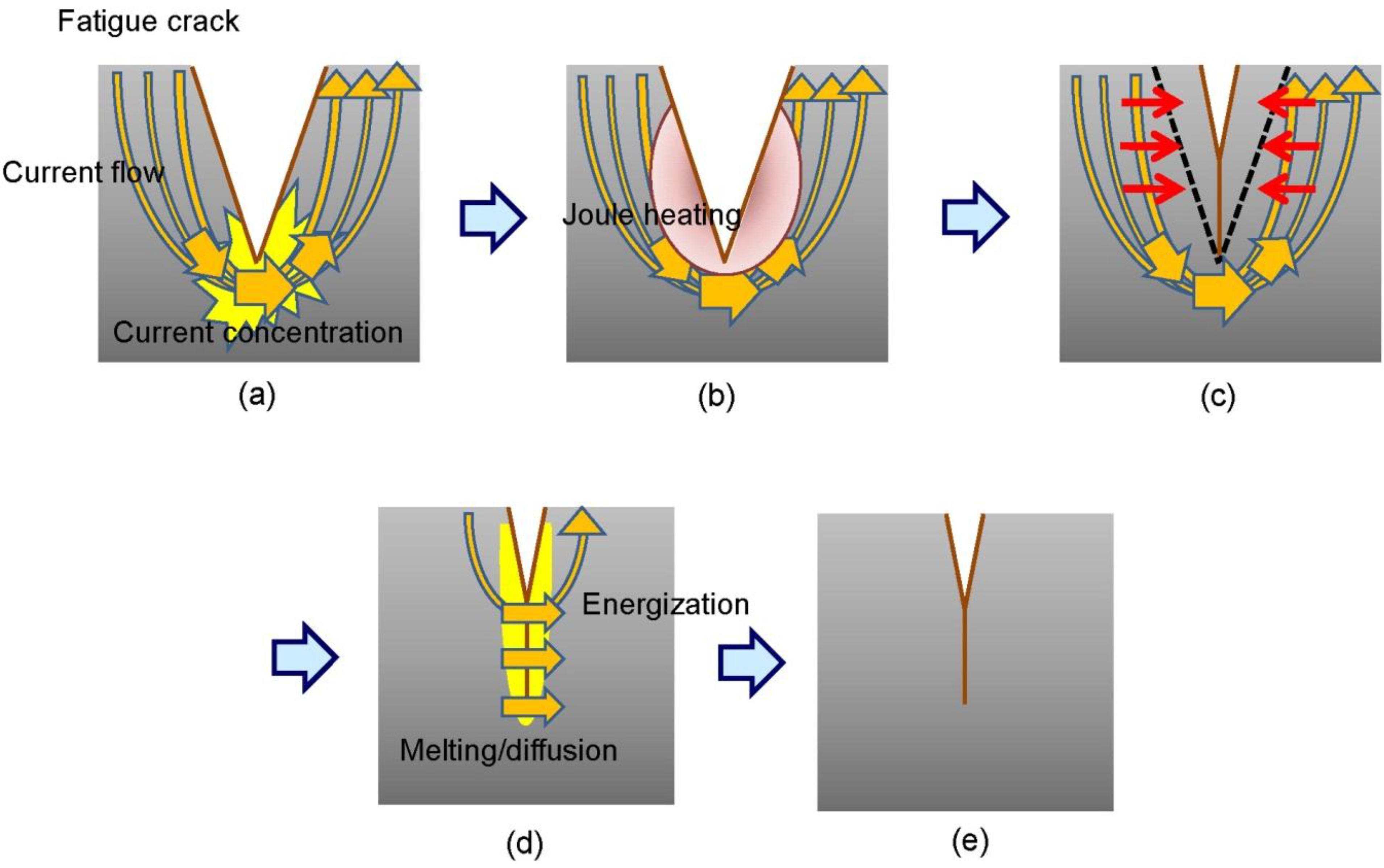
:1. Introduction
2. Experimental Details
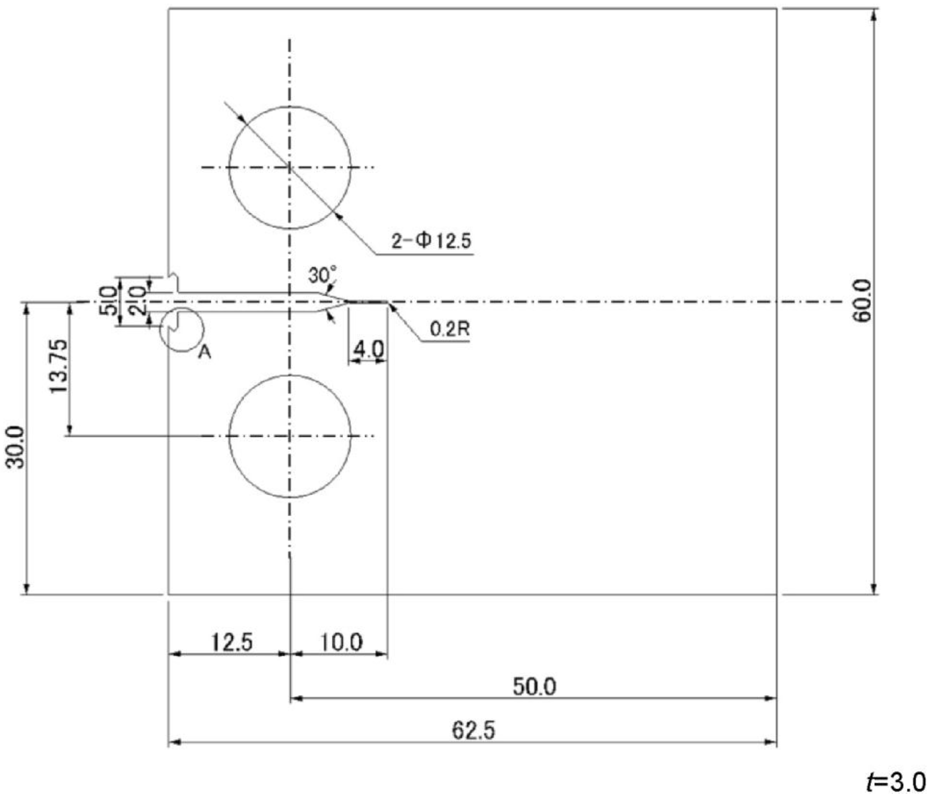
2.1. Samples
2.2. Experimental Conditions
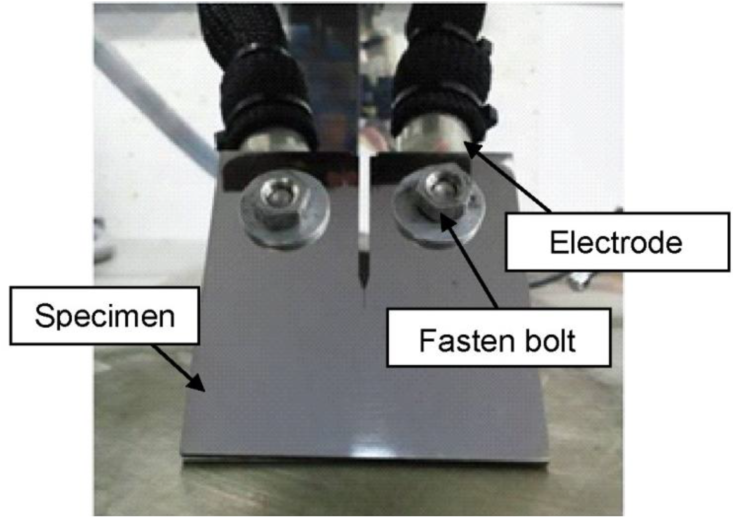
2.2.1. Fatigue Test Conditions

| Sample name | Sample A | Sample B | Sample C | Control |
|---|---|---|---|---|
| Stress ratio R | 0.05 | 0.05 | 0.05 | 0.05 |
| Frequency f [Hz] | 10 | 10 | 10 | 10 |
| Pre-crack length a [mm] | 3.0 | 6.0 | 8.0 | – |
| Stress intensity factor range ∆K [MPa·m1/2] | 35 | 15 | 25 | 15–35 |
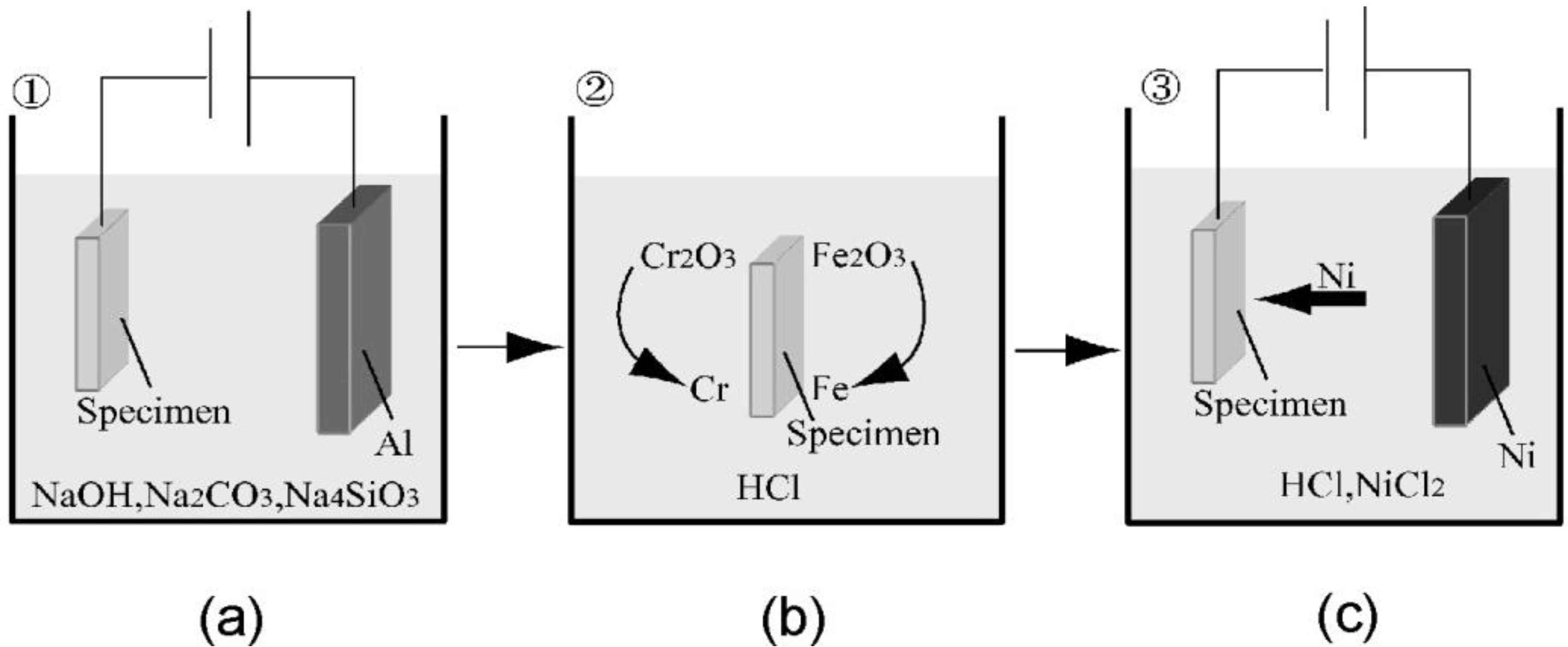
2.2.2. Surface-Activated Pre-Coating (SAPC)

2.2.3. Electropulsing Conditions
| Sample name | Sample A | Sample B | Sample C |
|---|---|---|---|
| Applied current [kA] | 9.0 | 6.0 | 8.0 |
| Pulse duration [msec] | 2.0 | 2.0 | 4.0 |
| Number of current application | 35 | 25 | 20 |
3. Experimental Section
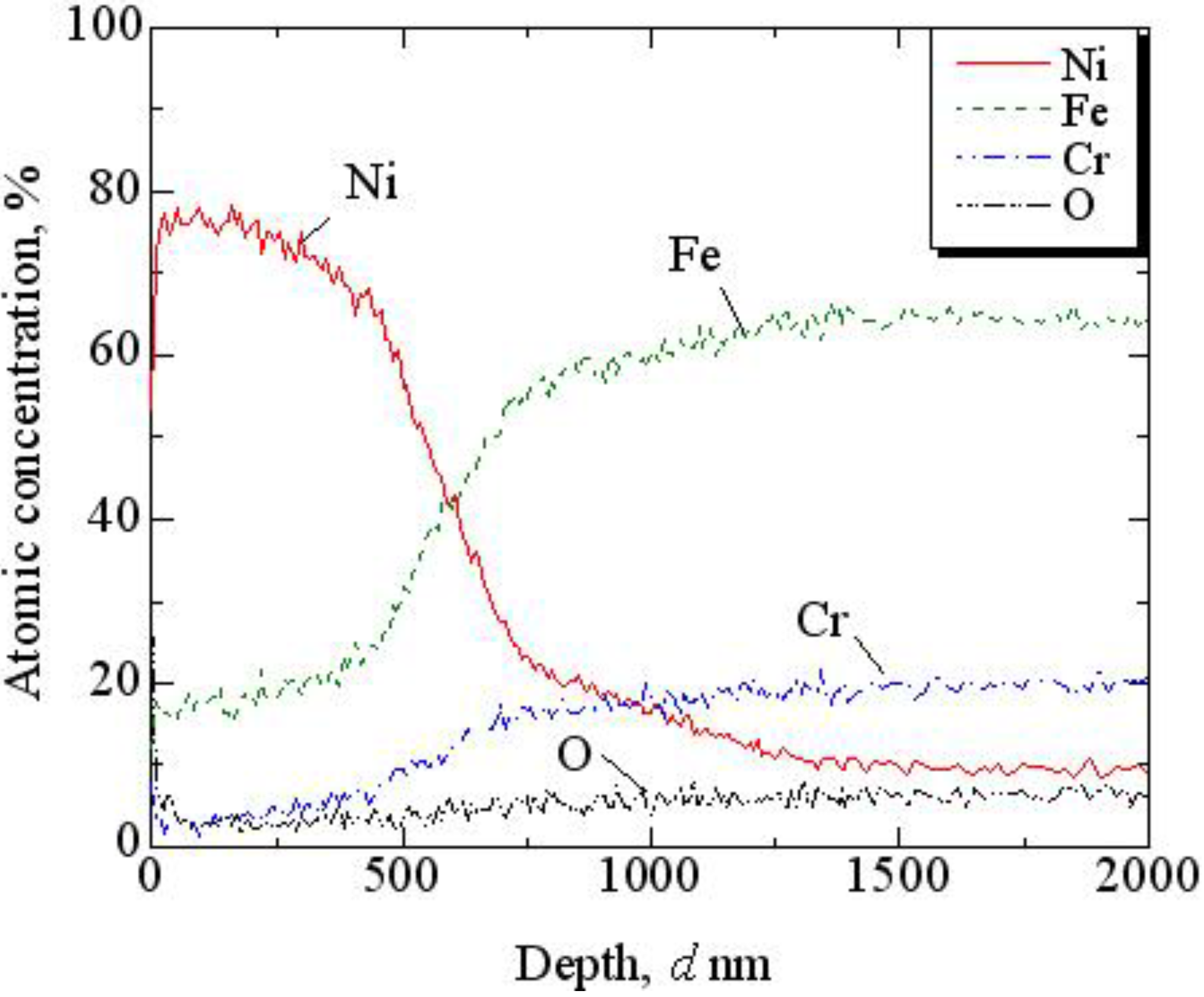
3.1. SAPC
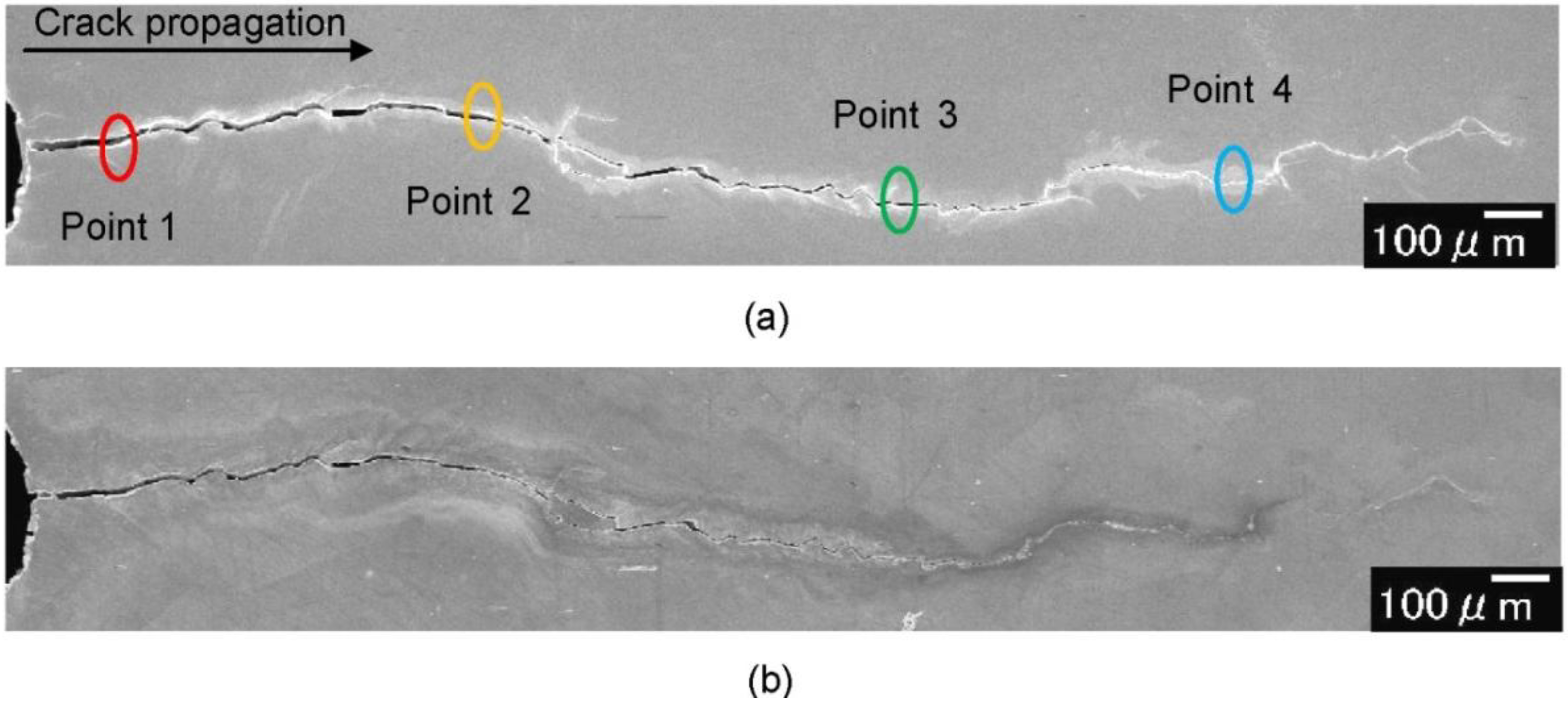
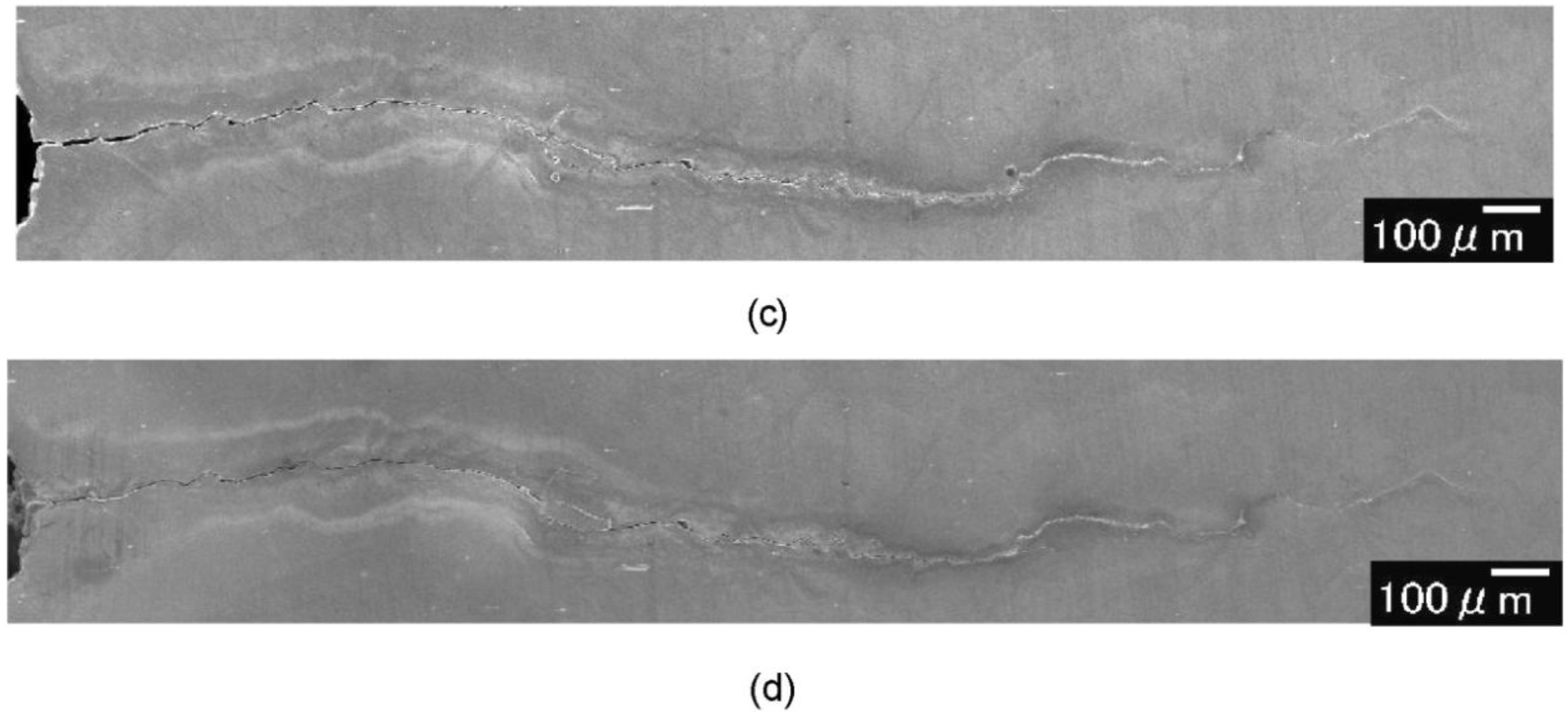
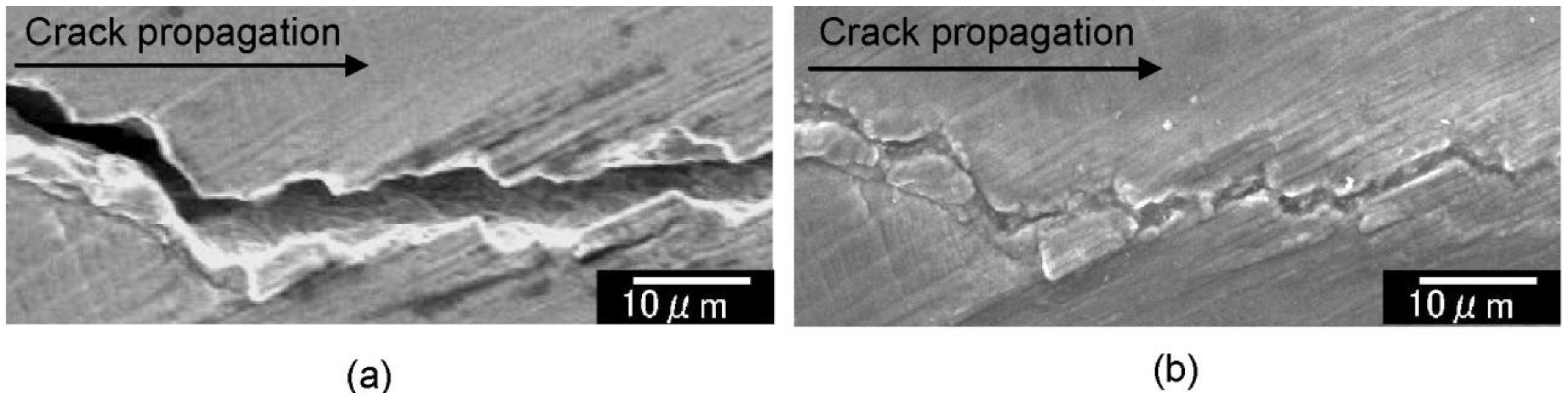
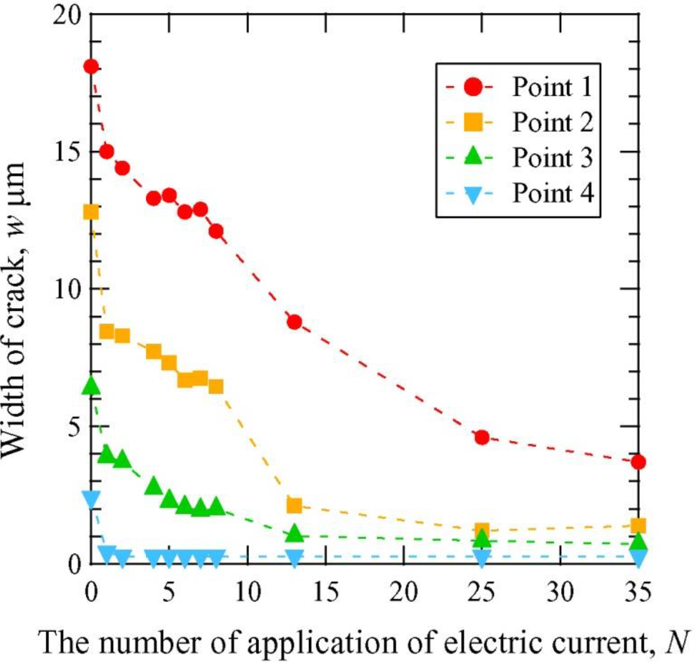
3.2. Fatigue Crack Observation


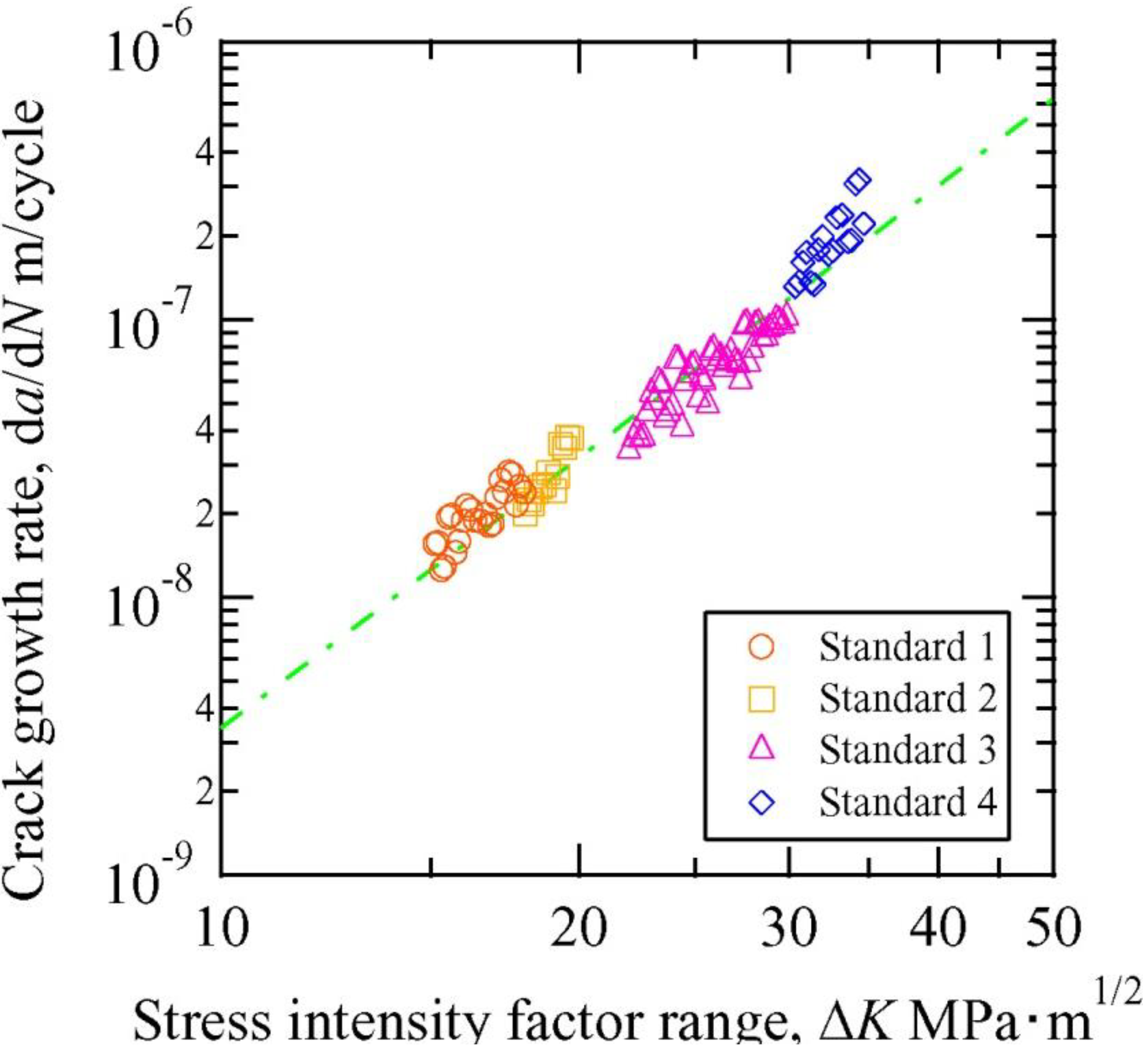
3.3. Evaluation of Fatigue Crack Growth


4. Discussions
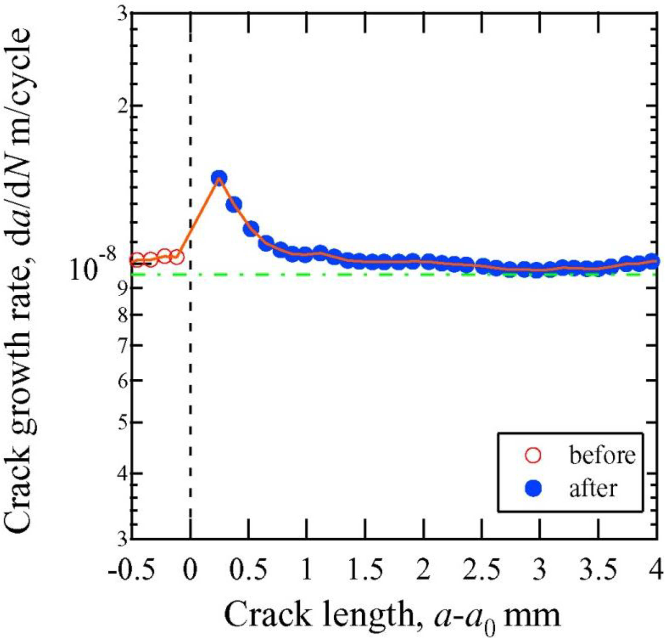
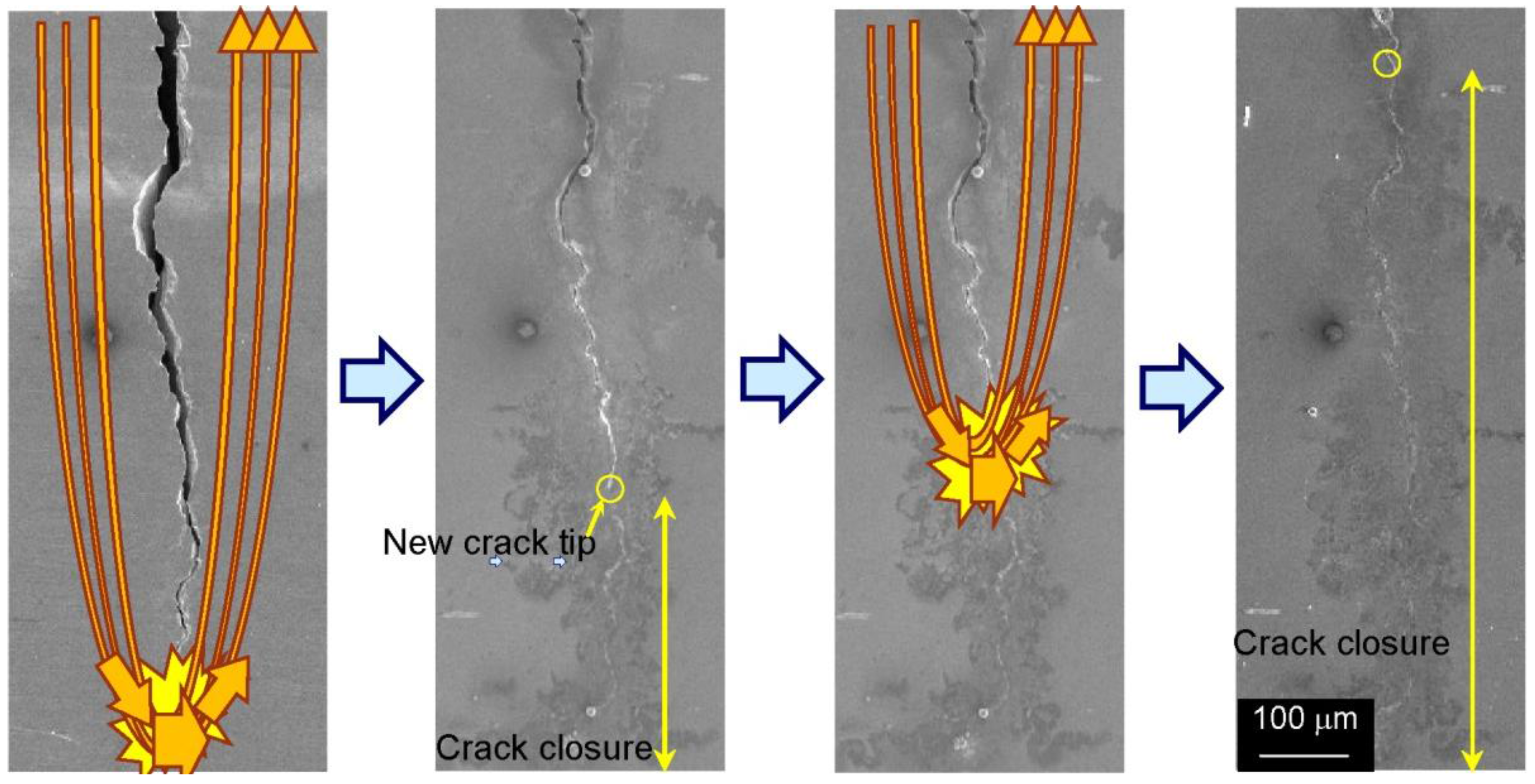
4.1. Fatigue Crack Closure

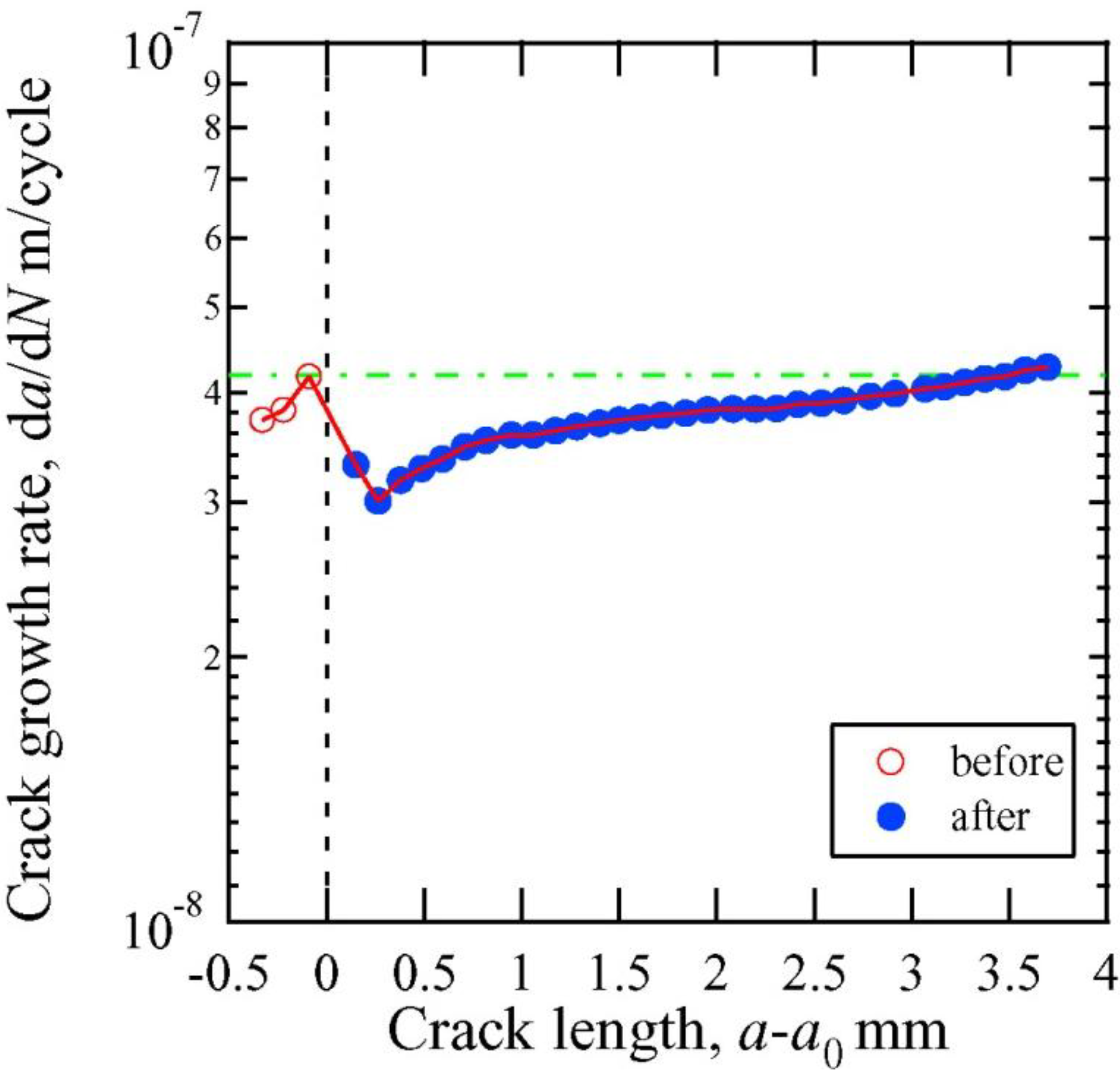
4.2. Fatigue Crack Growth Rate
5. Conclusions
Acknowledgments
Conflicts of Interest
References
- Wagner, L. Mechanical surface treatments on titanium, aluminum and magnesium alloys. Mater. Sci. Eng. A Struct. 1999, 263, 210–260. [Google Scholar]
- Nascimento, M.P.; Souza, R.C.; Pigatin, W.L.; Voorwald, H.J.C. Effects of surface treatments on the fatigue strength of AISI 4340 aeronautical steel. Int. J. Fatigue 2001, 23, 607–618. [Google Scholar] [CrossRef]
- Montross, C.S.; Wei, T.; Ye, L.; Clark, G.; Mai, Y.-W. Laser shock processing and its effects on microstructure and properties of metal alloys: A review. Int. J. Fatigue 2002, 24, 1021–1036. [Google Scholar] [CrossRef]
- Farrahi, G.H.; Ghadbeigi, H. An investigation into the effect of various surface treatments on fatigue life of a tool steel. J. Mater. Process. Technol. 2006, 174, 318–324. [Google Scholar] [CrossRef]
- White, S.R.; Sottos, N.R.; Geubelle, P.H.; Moore, J.S.; Kessler, M.R.; Sriram, S.R.; Brown, E.N.; Viswanathan, S. Autonomic healing of polymer composites. Nature 2001, 409, 794–797. [Google Scholar] [CrossRef] [PubMed]
- Chen, X.; Dam, M.A.; Ono, K.; Mal, A.; Shen, H.; Nutt, S.R.; Sheran, K.; Wudl, F. A thermally re-mendable cross-linked polymeric material. Science 2002, 295, 1698–1702. [Google Scholar] [CrossRef] [PubMed]
- Ando, K.; Shirai, Y.; Nakatani, M.; Kobayashi, Y.; Sato, S. (Crack-healing + proof test): A new methodology to guarantee the structural integrity of a ceramics component. J. Eur. Ceram. Soc. 2002, 22, 121–128. [Google Scholar] [CrossRef]
- Shinya, N.; Kyono, J.; Laha, K. Self-healing effect of Boron Nitride precipitation on creep cavitation in austenitic stainless steel. J. Intell. Mater. Syst. Struct. 2006, 17, 1127–1133. [Google Scholar] [CrossRef]
- Lumley, R.N. Self healing in metals; an emerging phenomenon in metallurgy. Mater. Sci. Forum 2007, 31, 40–51. [Google Scholar]
- Conrad, H. Electroplasticity in metals and ceramics. Mater. Sci. Eng. A Struct. 2000, 287, 276–287. [Google Scholar] [CrossRef]
- Yang, D.; Conrad, H. Exploratory study into the effects of an electric field and of high current density electropulsing on the plastic deformation of TiAl. Intermetallics 2001, 9, 943–947. [Google Scholar] [CrossRef]
- Xiao, S.H.; GuO, J.D.; Wu, S.D.; He, G.H.; Li, S.X. Recrystallization in fatigued copper single crystals under electropulsing. Scripta Mater. 2002, 46, 1–6. [Google Scholar] [CrossRef]
- Zhou, Y.; Xiao, S.; GuO, J. Recrystallized microstructure in cold worked brass produced by electropulsing treatment. Mater. Lett. 2004, 58, 1948–1951. [Google Scholar] [CrossRef]
- Zhang, W.; Sui, M.L.; Zhou, Y.Z.; Li, D.X. Evolution of microstructures in materials induced by electropulsing. Micron 2003, 34, 189–198. [Google Scholar] [CrossRef] [PubMed]
- To, S.; Zhu, Y.H.; Lee, W.B.; Liu, X.M.; Jiang, Y.B.; Tang, G.Y. Effects of current density on electropulsing-induced phase transformations in a Zn–Al based alloy. Appl. Phys. A 2009, 96, 939–944. [Google Scholar] [CrossRef]
- Nam, S.W.; Chung, H.-S.; Lo, Y.C.; Qi, L.; Li, J.; Lu, Y.; Johnson, A.T.C.; Jung, Y.; Nukala, P.; Agarwal, R. Electrical wind force-driven and dislocation-templated amorphization in phase-change nanowires. Science 2012, 336, 1561–1566. [Google Scholar] [CrossRef] [PubMed]
- Lloyd, J.R. Electromigration in integrated circuit conductors. J. Phys. D Appl. Phys. 1999, 32. [Google Scholar] [CrossRef]
- Mizubayashi, H.; Kameyama, N.; Hao, T.; Tanimoto, H. Crystallization under electropulsing suggesting a resonant collective motion of many atoms and modification of thermodynamic parameters in amorphous alloys. Phys. Rev. B 2001, 64. [Google Scholar] [CrossRef] [Green Version]
- Song, H.; Wang, Z.-J. Microcrack healing and local recrystallization in pre-deformed sheet by high density electropulsing. Mat. Sci. Eng. A Struct. 2008, 490, 1–6. [Google Scholar] [CrossRef]
- Zhu, Y.H.; To, S.; Lee, W.B.; Liu, X.M.; Jiang, Y.B.; Tang, G.Y. Effect of dynamic electropulsing on microstructure and elongation of a Zn–Al alloy. Mater. Sci. Eng. A Struct. 2009, 501, 125–132. [Google Scholar] [CrossRef]
- Conrad, H.; White, J.; Cao, W.D.; Lu, X.P.; Sprecher, A.S. Effect of electric current pulses on fatigue characteristics of polycrystalline copper. Mater. Sci. Eng. A Struct. 1991, 145, 1–12. [Google Scholar] [CrossRef]
- Sosnin, O.V.; Gromova, A.V.; Ivanov, Yu.F.; Konovalov, S.V.; Gromov, V.E.; Kozlov, E.V. Control of austenite steel fatigue strength. Int. J. Fatigue 2005, 27, 1186–1191. [Google Scholar] [CrossRef]
- Konovalov, S.V.; Atroshkina, A.A.; Ivanov, Yu.F.; Gromav, V.E. Evolution of dislocation substructures in fatigue loaded and failed stainless steel with the intermediate electropulsing treatment. Mater. Sci. Eng. A Struct. 2010, 527, 3040–3043. [Google Scholar] [CrossRef]
- Xiao, S.; Zhou, Y.; Guo, J.; Wu, S.; Yao, G.; Li, S.; He, G.; Zhou, B. The effect of high current pulsing on persistent slip bands in fatigued copper single crystals. Mater. Sci. Eng. A Struct. 2002, 332, 351–355. [Google Scholar] [CrossRef]
- Zhou, Y.; Zeng, Y.; He, G.; Zhou, B. The healing of quenched crack in 1045 steel under electropulsing. J. Mater. Res. 2001, 16, 17–19. [Google Scholar] [CrossRef]
- Zhou, Y.; Guo, J.; Gao, M.; He, G. Crack healing in a steel by using electropulsing technique. Mater. Lett. 2004, 58, 1732–1736. [Google Scholar] [CrossRef]
- Hosoi, A.; Nagahama, T.; Ju, Y. Fatigue crack healing by a controlled high density electric current field. Mater. Sci. Eng. A Struct. 2012, 533, 38–42. [Google Scholar] [CrossRef]
- Nishimoto, K.; Saida, K.; Kuroda, S. Removing of surface oxide film of SUS316 and improvement of diffusion-bondability of A6061 aluminum alloy to SUS 316 stainless steel using surface-activated pre-coating technique. Quart. J. Jpn. Weld. Soc. 2000, 18, 563–571. [Google Scholar] [CrossRef]
- Tang, D.W.; Zhou, B.L.; Cao, H.; He, G.H. Thermal stress relaxation behavior in thin films under transient laser-pulse heating. J. Appl. Phys. 1993, 73, 3749–3752. [Google Scholar] [CrossRef]
© 2013 by the authors; licensee MDPI, Basel, Switzerland. This article is an open access article distributed under the terms and conditions of the Creative Commons Attribution license (http://creativecommons.org/licenses/by/3.0/).
Share and Cite
Hosoi, A.; Kishi, T.; Ju, Y. Healing of Fatigue Crack by High-Density Electropulsing in Austenitic Stainless Steel Treated with the Surface-Activated Pre-Coating. Materials 2013, 6, 4213-4225. https://doi.org/10.3390/ma6094213
Hosoi A, Kishi T, Ju Y. Healing of Fatigue Crack by High-Density Electropulsing in Austenitic Stainless Steel Treated with the Surface-Activated Pre-Coating. Materials. 2013; 6(9):4213-4225. https://doi.org/10.3390/ma6094213
Chicago/Turabian StyleHosoi, Atsushi, Tomoya Kishi, and Yang Ju. 2013. "Healing of Fatigue Crack by High-Density Electropulsing in Austenitic Stainless Steel Treated with the Surface-Activated Pre-Coating" Materials 6, no. 9: 4213-4225. https://doi.org/10.3390/ma6094213