
Fast-Embeddable Grooved Microneedles by Shear Actuation for Accurate Transdermal Drug Delivery

Abstract
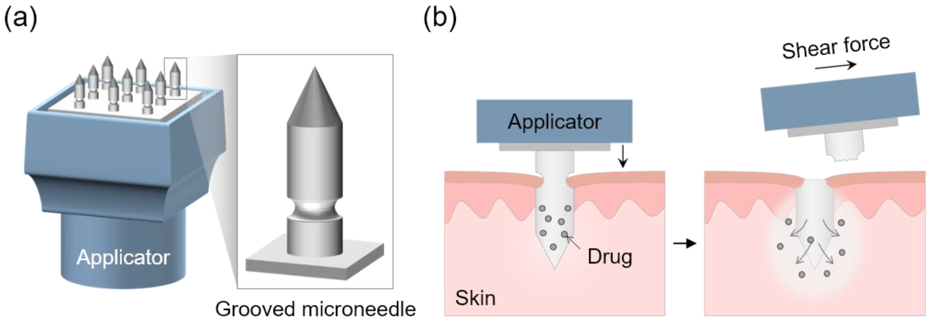
:1. Introduction
2. Materials and Methods
2.1. Materials
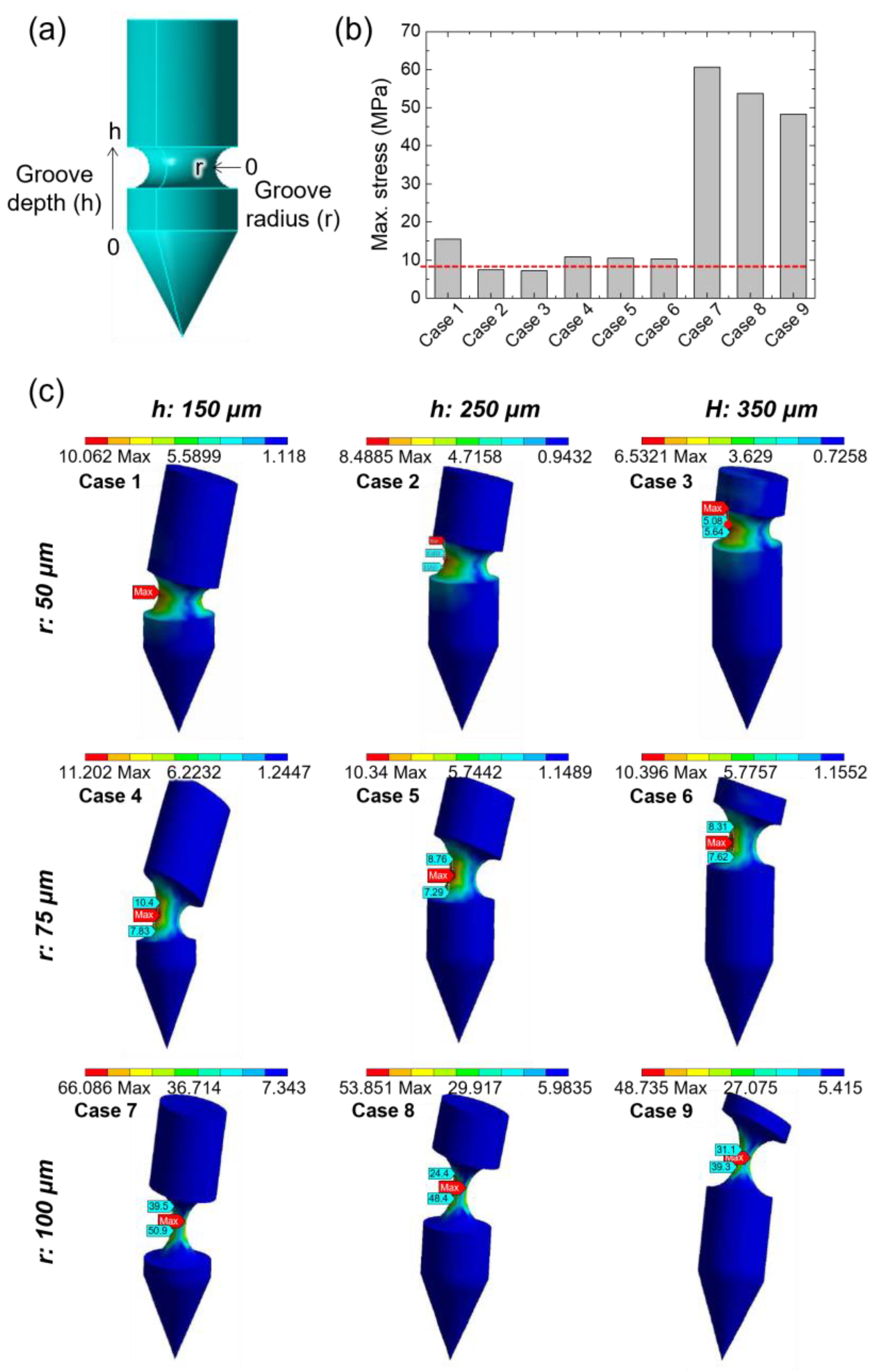
2.2. Finite Element Analysis
2.3. Fabrication of TCA-Loaded Grooved MN Arrays
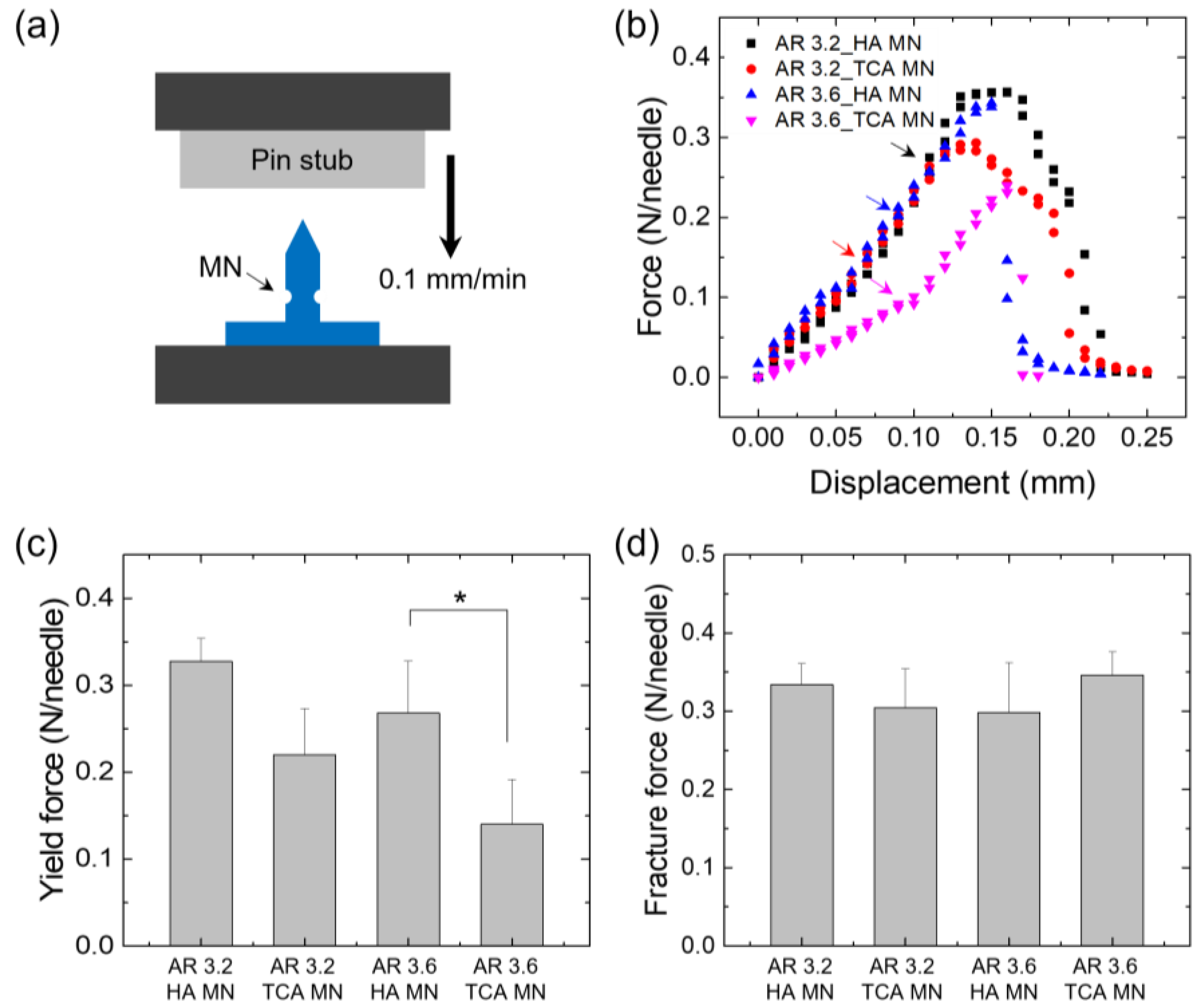
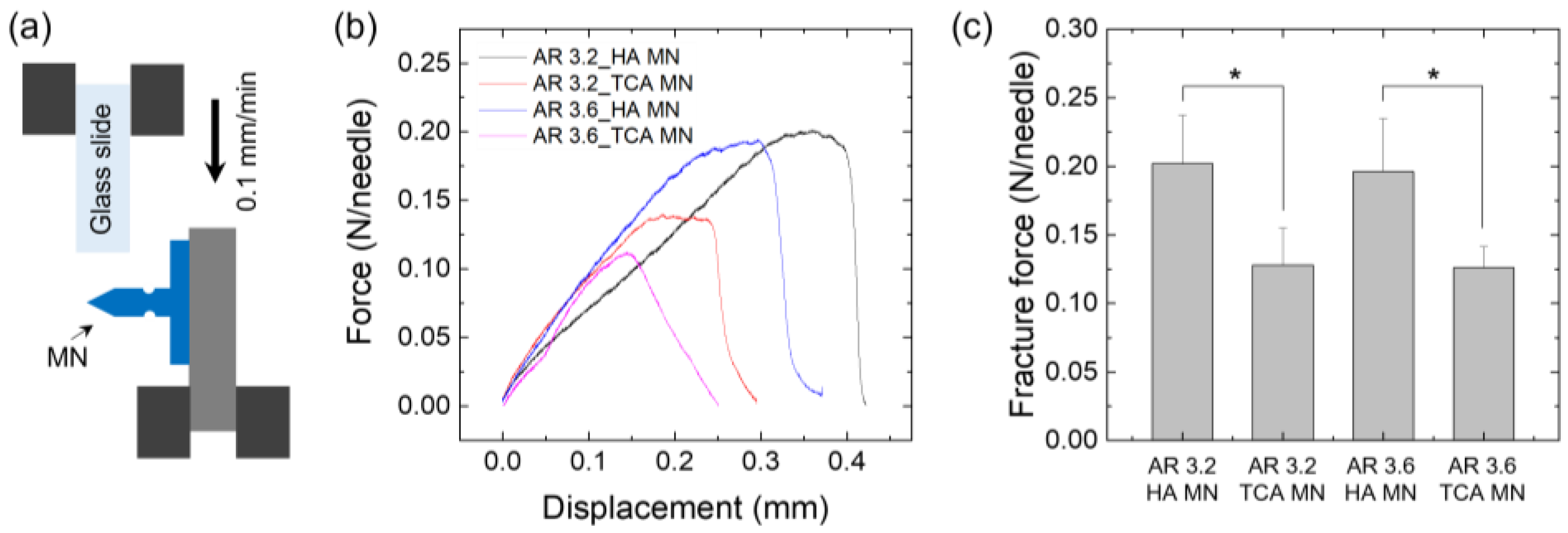
2.4. Evaluation of Mechanical Properties
2.5. Measurement of Shear Fracture Force
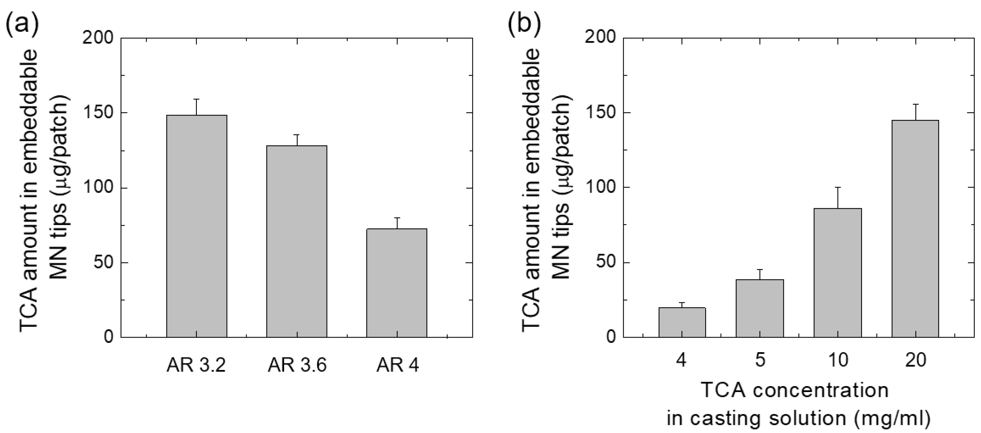
2.6. Quantitative Evaluation of TCA Loaded in MN
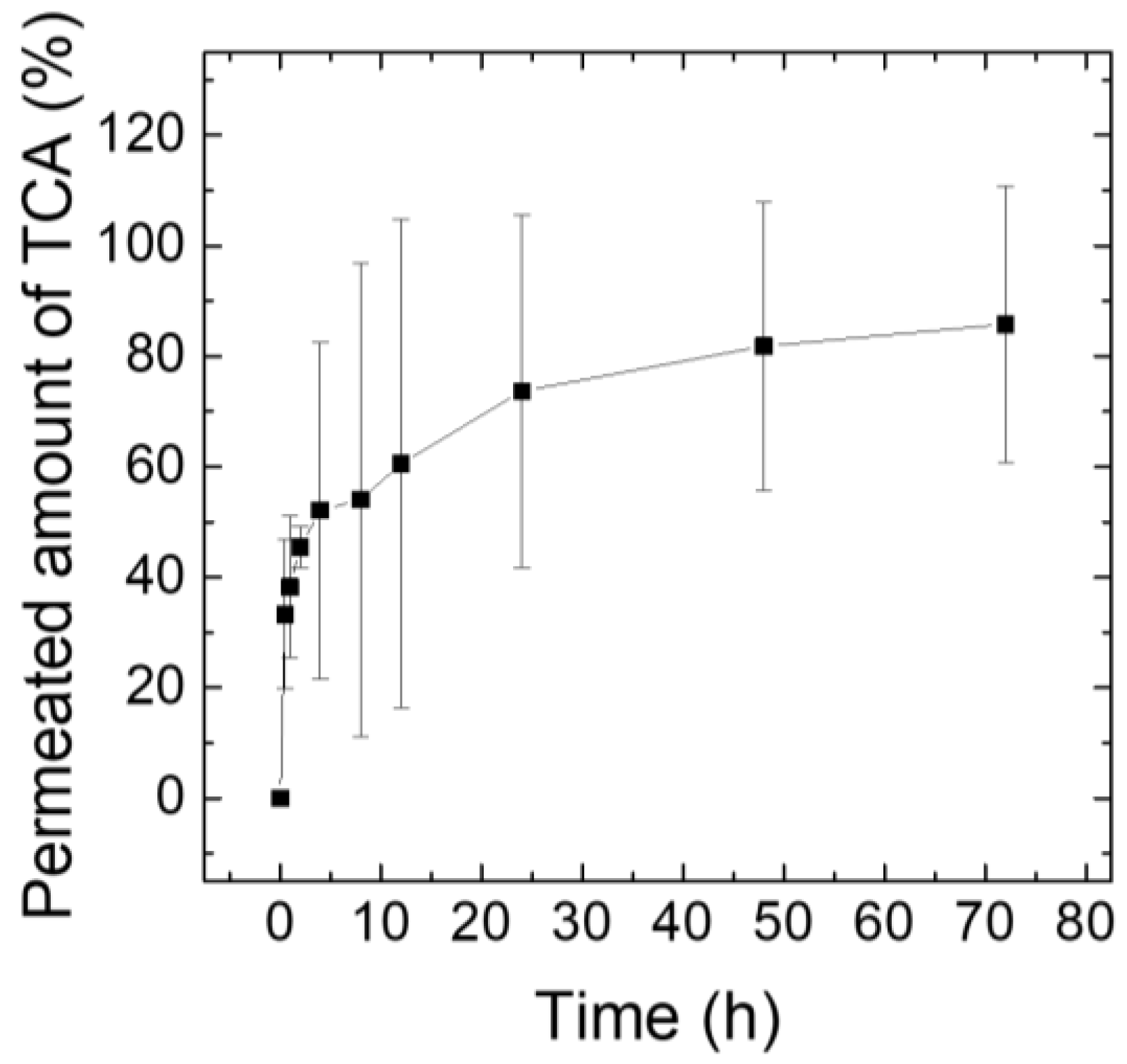
2.7. Ex Vivo Drug Release Test Using Franz Diffusion Cells
2.8. Animals Experimental Protocols and In Vivo Application of TCA-Loaded MNs Using a Customized Applicator
3. Results and Discussion
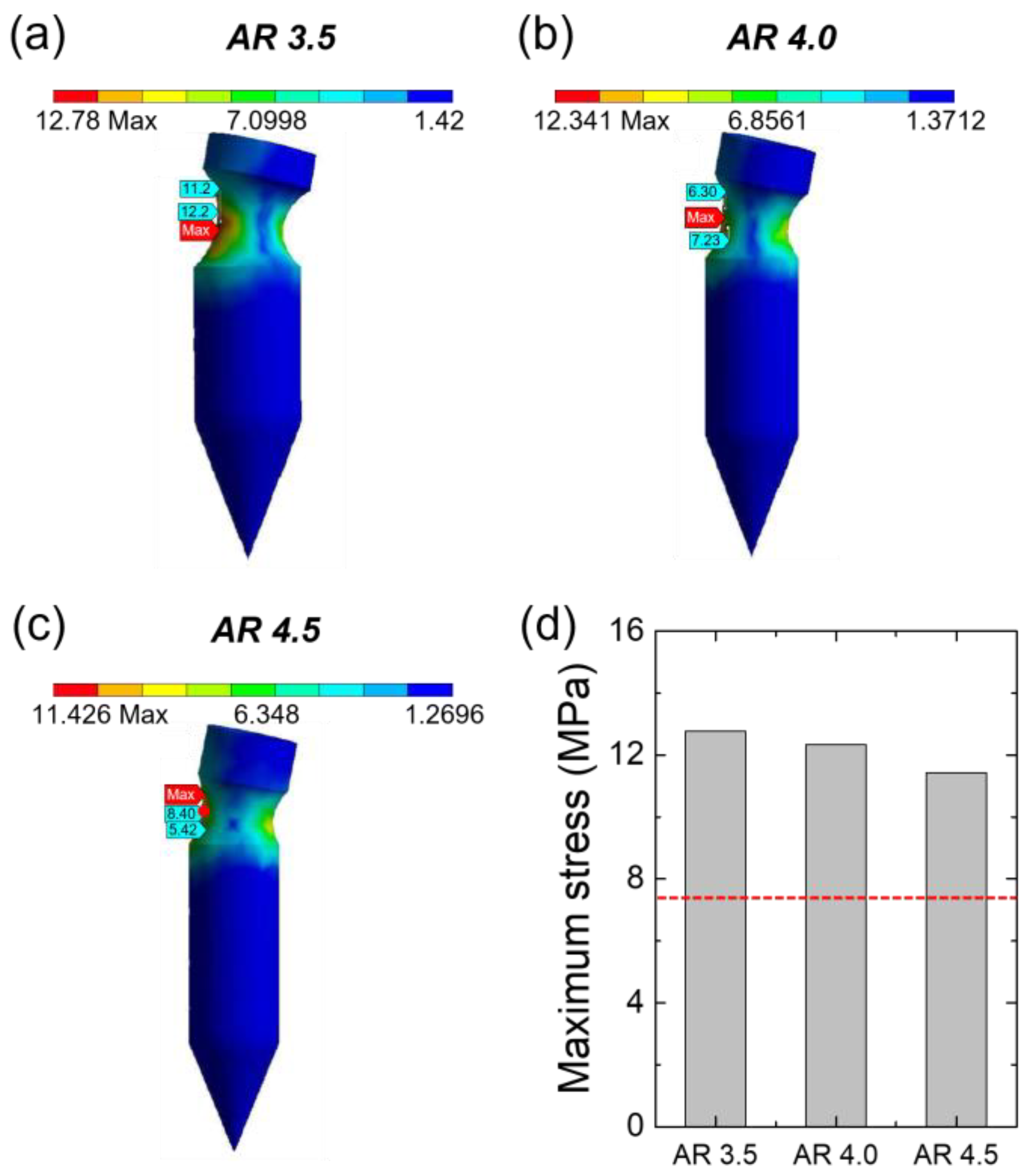
3.1. Simulation to Determine the Structure of the Grooved MN
3.2. Fabrication of Grooved Microneedle Patches
3.3. Mechanical Properties
3.4. Quantification of TCA Loaded in the MNs
3.5. Ex Vivo TCA Release Test Using Franz Diffusion Cells
3.6. In Vivo Application of TCA-Loaded MNs
4. Conclusions
Author Contributions
Funding
Institutional Review Board Statement
Informed Consent Statement
Data Availability Statement
Conflicts of Interest
References
- Guillot, A.J.; Cordeiro, A.S.; Donnelly, R.F.; Montesinos, M.C.; Garrigues, T.M.; Melero, A. Microneedle-based delivery: An overview of current applications and trends. Pharmaceutics 2020, 12, 569. [Google Scholar] [CrossRef] [PubMed]
- Olowe, M.; Parupelli, S.K.; Desai, S. A review of 3D-printing of microneedles. Pharmaceutics 2022, 14, 2693. [Google Scholar] [CrossRef] [PubMed]
- Ingrole, R.S.J.; Gill, H.S. Microneedle coating methods: A review with a perspective. J. Pharmacol. Exp. Ther. 2019, 370, 555–569. [Google Scholar] [CrossRef] [PubMed]
- Turner, J.G.; White, L.R.; Estrela, P.; Leese, H.S. Hydrogel-forming microneedles: Current advancements and future trends. Macromol. Biosci. 2021, 21, 2000307. [Google Scholar] [CrossRef]
- Ingrole, R.S.J.; Azizoglu, E.; Dul, M.; Birchall, J.C.; Gill, H.S.; Prausnitz, M.R. Trends of microneedle technology in the scientific literature, patent, clinical trials and internet activity. Biomaterials 2021, 267, 120491. [Google Scholar] [CrossRef]
- Waghule, T.; Singhvi, G.; Dubey, S.K.; Pandey, M.M.; Gupta, G.; Singh, M.; Dua, K. Microneedles: A smart approach and increasing potential for transdermal drug delivery system. Biomed. Pharmacother. 2019, 109, 1249–1258. [Google Scholar] [CrossRef]
- Ita, K. Dissolving microneedles for transdermal drug delivery: Advances and challenges. Biomed. Pharmacother. 2017, 93, 1116–1127. [Google Scholar] [CrossRef]
- Lee, H.; Song, C.; Baik, S.; Kim, D.; Hyeon, T.; Kim, D.H. Device-assisted transdermal drug delivery. Adv. Drug Deliv. Rev. 2018, 127, 35–45. [Google Scholar] [CrossRef]
- Hao, Y.; Li, W.; Zhou, X.; Yang, F.; Qian, Z. Microneedles-Based Transdermal Drug Delivery Systems: A Review. J. Biomed. Nanotechnol. 2017, 13, 1581–1597. [Google Scholar] [CrossRef]
- Seong, K.-Y.; Seo, M.-S.; Hwang, D.Y.; O’Cearbhaill, E.D.; Sreenan, S.; Karp, J.M.; Yang, S.Y. A self-adherent, bullet-shaped microneedle patch for controlled transdermal delivery of insulin. J. Control. Release 2017, 265, 47–56. [Google Scholar] [CrossRef]
- Chang, H.; Zheng, M.; Yu, X.; Than, A.; Seeni, R.Z.; Kang, R.; Tian, J.; Khanh, D.P.; Liu, L.; Chen, P.; et al. A swellable microneedle patch to rapidly extract skin interstitial fluid for timely metabolic analysis. Adv. Mater. 2017, 29, 1702243. [Google Scholar] [CrossRef]
- Li, Y.; Bi, D.; Hu, Z.; Yang, Y.; Liu, Y.; Leung, W.K. Hydrogel-forming microneedles with applications in oral diseases management. Materials 2023, 16, 4805. [Google Scholar] [CrossRef]
- Chang, H.; Chew, S.W.T.; Zheng, M.; Lio, D.C.S.; Wiraja, C.; Mei, Y.; Ning, X.; Cui, M.; Than, A.; Shi, P.; et al. Cryomicroneedles for transdermal cell delivery. Nat. Biomed. Eng. 2021, 5, 1008–1018. [Google Scholar] [CrossRef]
- Vinayakumar, K.B.; Kulkarni Prachit, G.; Nayak, M.M.; Dinesh, N.S.; Hegde Gopalkrishna, M.; Ramachandra, S.G.; Rajanna, K. A hollow stainless steel microneedle array to deliver insulin to a diabetic rat. J. Micromech. Microeng. 2016, 26, 065013. [Google Scholar] [CrossRef]
- Gardeniers, H.J.G.E.; Luttge, R.; Berenschot, E.J.W.; de Boer, M.J.; Yeshurun, S.Y.; Hefetz, M.; van’t Oever, R.; van den Berg, A. Silicon micromachined hollow microneedles for transdermal liquid transport. Microelectromech. Syst. 2003, 12, 855–862. [Google Scholar] [CrossRef] [Green Version]
- Leone, M.; Mönkäre, J.; Bouwstra, J.A.; Kersten, G. Dissolving Microneedle Patches for Dermal Vaccination. Pharm. Res. 2017, 34, 2223–2240. [Google Scholar] [CrossRef] [Green Version]
- Du, G.; Zhang, Z.; He, P.; Zhang, Z.; Sun, X. Determination of the mechanical properties of polymeric microneedles by micromanipulation. J. Mech. Behav. Biomed. Mater. 2021, 117, 104384. [Google Scholar] [CrossRef]
- Lee, S.; Fakhraei Lahiji, S.; Jang, J.; Jang, M.; Jung, H. Micro-Pillar Integrated Dissolving Microneedles for Enhanced Transdermal Drug Delivery. Pharmaceutics 2019, 11, 402. [Google Scholar] [CrossRef] [Green Version]
- Lee, J.; Park, S.H.; Seo, I.H.; Lee, K.J.; Ryu, W. Rapid and repeatable fabrication of high A/R silk fibroin microneedles using thermally-drawn micromolds. Eur. J. Pharm. Biopharm. 2015, 94, 11–19. [Google Scholar] [CrossRef]
- Ita, K. Transdermal Delivery of Drugs with Microneedles-Potential and Challenges. Pharmaceutics 2015, 7, 90–105. [Google Scholar] [CrossRef] [Green Version]
- Fan, L.; Zhang, X.; Nie, M.; Xu, Y.; Wang, Y.; Shang, L.; Zhao, Y.; Zhao, Y. Photothermal responsive microspheres-triggered separable microneedles for versatile drug delivery. Adv. Func. Mater. 2022, 32, 2110746. [Google Scholar] [CrossRef]
- Wang, C.; Jiang, X.; Zeng, Y.; Terry, R.N.; Li, W. Rapidly separable microneedle patches for controlled release of therapeutics for long-acting therapies. Med. Drug Discov. 2022, 13, 100118. [Google Scholar] [CrossRef]
- Dawud, H.; Ammar, A.A. Rapidly dissolving microneedles for the delivery of steroid-loaded nanoparticles intended for the treatment of inflammatory skin disease. Phamaceutics 2023, 15, 526. [Google Scholar] [CrossRef] [PubMed]
- Chen, M.C.; Huang, S.F.; Lai, K.Y.; Ling, M.H. Fully embeddable chitosan microneedles as a sustained release depot for intradermal vaccination. Biomaterials 2013, 34, 3077–3086. [Google Scholar] [CrossRef] [PubMed]
- Lahiji, S.F.; Dangol, M.; Jung, H. A patchless dissolving microneedle delivery system enabling rapid and efficient transdermal drug delivery. Sci. Rep. 2015, 5, 7914. [Google Scholar] [CrossRef] [Green Version]
- Choi, I.-J.; Kang, A.; Ahn, M.-H.; Jun, H.; Baek, S.-K.; Park, J.-H.; Na, W.; Choi, S.-O. Insertion-responsive microneedles for rapid intradermal delivery of canine influenza vaccine. J. Control. Release 2018, 286, 460–466. [Google Scholar] [CrossRef]
- Li, W.; Terry, R.N.; Tang, J.; Feng, M.R.; Schwendeman, S.P.; Prausnitz, M.R. Rapidly separable microneedle patch for the sustained release of a contraceptive. Nat. Biomed. Eng. 2019, 3, 220–229. [Google Scholar] [CrossRef]
- Lee, Y.; Kumar, S.; Kim, S.H.; Seong, K.-Y.; Lee, H.; Kim, C.; Jung, Y.-S.; Yang, S.Y. Odorless glutathione microneedle patches for skin whitening. Phamaceutics 2020, 12, 100. [Google Scholar] [CrossRef] [Green Version]
- Chandrasekharan, A.; Hwang, Y.J.; Seong, K.-Y.; Park, S.; Kim, S.; Yang, S.Y. Acid-treated water-soluble chitosan suitable for microneedle-assisted intracutaneous drug delivery. Pharmaceutics 2019, 11, 209. [Google Scholar] [CrossRef] [Green Version]
- Kim, M.J.; Seong, K.-Y.; Kim, D.S.; Jeong, J.S.; Kim, S.Y.; Lee, S.; Yang, S.Y.; An, B.-S. Minoxidil-loaded hyaluronic acid dissolving microneedles to alleviate hair low in an alopecia animal model. Acta Biomater. 2022, 143, 189–202. [Google Scholar] [CrossRef]
- Roche, J. Introducing simple harmonic motion. Phys. Educ. 2002, 37, 497. [Google Scholar] [CrossRef]
- Rolland, J.P.; Hagberg, E.C.; Denison, G.M.; Carter, K.R.; De Simone, J.M. High-resolution soft lithography: Enabling materials for nanotechnologies. Angew. Chem. Int. Ed. Engl. 2004, 43, 5796–5799. [Google Scholar] [CrossRef]
- Cevc, G.; Blume, G.; Schatzlein, A. Transfersomes-mediated transepiderma delivery improves the regio-specificity and biological activity of corticosteroids in vivo. J. Control. Release 1997, 45, 211–226. [Google Scholar] [CrossRef]
- Cevc, G.; Blume, G. Biological activity and characteristics of triamcinolone-acetonide formulated with the self-regulating drug carriers, Transfersomes. Biochim. Biophys. Acta 2003, 1614, 156–164. [Google Scholar] [CrossRef] [Green Version]
- Kumaresan, M. Intralesional steroids for alopecia areata. Int. J. Trichol. 2010, 2, 63–65. [Google Scholar] [CrossRef] [Green Version]
- Herbert Pratt, C.; King, L.E., Jr.; Messenger, A.G.; Christiano, A.M.; Sundberg, J.P. Alopecia areata. Nat. Rev. Dis. Primers 2017, 3, 17011. [Google Scholar] [CrossRef] [Green Version]
- Chu, T.W.; Aljasser, M.; Alharbi, A.; Abahussein, O.; McElwee, K.; Shapiro, J. Benefit of different concentrations of intralesional triamcinolone acetonide in alopecia areata: An intrasubject pilot study. J. Am. Acad. Dermatol. 2015, 73, 338–340. [Google Scholar] [CrossRef]
- Abell, E.; Munro, D.D. Intralesional treatment of alopecia areata with triamcinolone acetonide by jet injectior. Br. J. Dermatol. 1973, 88, 55–60. [Google Scholar] [CrossRef]
- Barletta, M.; Gasques, L. Successful Treatment of Alopecia Areata Patches with Triamcinolone Acetonide Using MMP®: Report of 2 Cases. Ski. Appendage Disord. 2020, 6, 229–234. [Google Scholar] [CrossRef]
- Yim, S.-G.; Hwang, Y.-H.; An, S.; Seong, K.-Y.; Kim, S.-Y.; Kim, S.; Lee, H.; Lee, K.-O.; Kim, M.-Y.; Kim, D.; et al. Low-temperature multiple micro-dispensing on microneedles for accurate transcutaneous smallpox vaccination. Vaccines 2022, 10, 561. [Google Scholar] [CrossRef]


| Grooved MNs | |||||||||
|---|---|---|---|---|---|---|---|---|---|
| Case 1 | Case 2 | Case 3 | Case 4 | Case 5 | Case 6 | Case 7 | Case 8 | Case 9 | |
| Groove radius (r, μm) | 50 | 50 | 50 | 75 | 75 | 75 | 100 | 100 | 100 |
| Groove depth (h, μm) | 150 | 250 | 350 | 150 | 250 | 350 | 150 | 250 | 350 |
| Aspect Ratio | Metal MN | TCA-Loaded MN | ||||
|---|---|---|---|---|---|---|
| 3.2 | 3.6 | 4 | 3.2 | 3.6 | 4 | |
| Tip height (μm) | 812 ± 9 | 820 ± 5 | 791 ± 5 | 804 ± 5 | 801 ± 11 | N.A.* |
| Base diameter (μm) | 249 ± 5 | 227 ± 4 | 204 ± 5 | 183 ± 6 | 192 ± 3 | N.A.* |
| Groove diameter (μm) | 187 ± 3 | 186 ± 3 | 171 ± 1 | 138 ± 3 | 154 ± 6 | N.A.* |
Disclaimer/Publisher’s Note: The statements, opinions and data contained in all publications are solely those of the individual author(s) and contributor(s) and not of MDPI and/or the editor(s). MDPI and/or the editor(s) disclaim responsibility for any injury to people or property resulting from any ideas, methods, instructions or products referred to in the content. |
© 2023 by the authors. Licensee MDPI, Basel, Switzerland. This article is an open access article distributed under the terms and conditions of the Creative Commons Attribution (CC BY) license (https://creativecommons.org/licenses/by/4.0/).
Share and Cite
Yim, S.-G.; Seong, K.-Y.; Thamarappalli, A.; Lee, H.; Lee, S.; Lee, S.; Kim, S.; Yang, S.-Y. Fast-Embeddable Grooved Microneedles by Shear Actuation for Accurate Transdermal Drug Delivery. Pharmaceutics 2023, 15, 1966. https://doi.org/10.3390/pharmaceutics15071966
Yim S-G, Seong K-Y, Thamarappalli A, Lee H, Lee S, Lee S, Kim S, Yang S-Y. Fast-Embeddable Grooved Microneedles by Shear Actuation for Accurate Transdermal Drug Delivery. Pharmaceutics. 2023; 15(7):1966. https://doi.org/10.3390/pharmaceutics15071966
Chicago/Turabian StyleYim, Sang-Gu, Keum-Yong Seong, Akash Thamarappalli, Hyeseon Lee, Seungsoo Lee, Sanha Lee, Semin Kim, and Seung-Yun Yang. 2023. "Fast-Embeddable Grooved Microneedles by Shear Actuation for Accurate Transdermal Drug Delivery" Pharmaceutics 15, no. 7: 1966. https://doi.org/10.3390/pharmaceutics15071966