
Combining Adaptive Holonic Control and ISA-95 Architectures to Self-Organize the Interaction in a Worker-Industrial Robot Cooperative Workcell


1
Department of Visual Assistance Technologies, Fraunhofer Institute for Computer Graphic Research IGD, 18059 Rostock, Germany
2
Institute of Computer Science, University of Rostock, 18057 Rostock, Germany
*
Author to whom correspondence should be addressed.
Future Internet 2017, 9(3), 35; https://doi.org/10.3390/fi9030035
Submission received: 20 June 2017
/
Revised: 10 July 2017
/
Accepted: 11 July 2017
/
Published: 14 July 2017
Abstract
:Self-Organization is a spontaneous trend which exists in nature among different organisms. Self-organization refers to the process where some form of an overall order arises in a group due to the local interaction among the members of this group. In manufacturing, a similar definition of a Reconfigurable Manufacturing System (RMS) can be found. RMS is a system where the production components and functions can be modified, rearranged and/or interchanged in a timely and cost-effective manner to quickly respond to the production requirements. The definition of the RMS concept implies that the self-organization is an important key factor to fulfil that concept. A case study where a cooperation among a variable number of Industrial Robots (IRs) and workers is studied to show the importance of the research problem. The goal of the paper is to offer a suitable generic control and interaction architecture solution model, which obtains the self-organization from the RMS point of view. Ultimately, applying the proposed solution concept to the case study.
1. Introduction, Motivation, and Related Research
Human-Robot Interaction (HRI) is an attractive field of study for many scholars from different research domains. HRI focuses on understanding, designing and evaluating robotics systems which involve the human as an essential element of these systems [1]. HRI originates from a literature roots, as the fundamentals of the HRI have been stated by author Isaac Asimov in his novel “I, Robot” [2]. The first two fundamentals are as following:
- A robot may not injure a human being or, through interaction, allow a human to come to harm.
- A robot must obey the orders which are given to it by the human beings.
Those two mentioned fundamentals above became later the inspiration for the scientific researchers to formulate the main HRI problems. Scientifically speaking, the first fundamental addresses the problem of a safe physical HRI, while the second fundamental addresses the problem of an HRI information communication and control.
In industry, a safe physical HRI presented a great focus of study in the last decades [3]. As a result of this focus, a new generation of safe cooperative IRs are now available in the commercial market. Examples of these robots are KUKA lightweight (KUKA Robotics, Augsburg, Germany), Rethink Baxter (Rethink Robotics, Boston, MA, USA), YuMi ABB dual arm (ABB Robotics, Zürich, Switzerland), and Universal Robots (Universal Robots, Odense, Denmark). These IRs apply different technologies and methodologies to ensure the safe cooperation with the human co-worker [4]. On the contrary, the second HRI fundamental concerns the information control still did not get the proper amount of attention, although it is as much important as the first fundamental. Which motivates us to put more research focus on the second HRI fundamental during this work.
The existence of the safe cooperative IR added a new dimension to the flexibility of the RMS [5]. This dimension stems from the fact that the cooperative IR is designed to operate in contact with a co-worker. Putting into consideration that the nature of the cooperative IR is very different form the advanced automatic machines such as the Computer Numerical Control (CNC) machines which can provide a high level of flexibility as well. The first difference is the degree of the cooperation. In case of a cooperative workcell, a real physical cooperation between the IR and the co-worker can be established. While the physical cooperation between a CNC machine and a worker can never happen. The second difference is the degree of flexibility. On the one hand, The CNC machine can manufacture a whole new product from scratch without any direct interference from the worker. The CNC machine high level of flexibility comes with the high cost of the machine hardware and its CAD/CAM software, yet the production volume is very limited. On the other hand, the cooperative IR has to cooperate with the worker to provide the flexibility, however this flexibility can be afforded by a lower cost than the CNC machine and with higher production volume. In other words—in case of the CNC machine—the worker either operates the machine or completes the work of it in another manufacturing stage, this is why the worker never been called a co-worker in case of a CNC machine.
Other RMS systems have been studied in [6,7]. The focus of [6] is to evaluate two different solution approaches to implement the holonic control solution for a modular feeder subsystem of an experimental Reconfigurable Assembly System (RAS). One approach uses the IEC-61499 (IEC: International Electrotechnical Commission) Function Block (FB) technology and the other uses the agent technology. The research does not combine the two technologies together, but it compares them. Then it evaluates them based on the qualitative and quantitative performance of different four hardware configurations for the RAS. The research results state that agent technology requires less effort and time than IEC-61499 FB to implement three configurations of the RAS, as IEC-61499 FB lacks of inter-platform communication flexibility. An Intelligent control of an airport Baggage Handling System (BHS) has been studied in [7] as an RMS case-study. It provides an extended customized Multi-Agent System (MAS) solution, by modeling every component of the BHS as an IEC-61499 FB. Basically it is dividing the whole conveyor transportation system into many segments. Every conveyor segment is presented as a customized FB. Moreover it models every bag over the BHS as another customized autonomous FB. All the instances of the conveyor segment FB and the bag FB are composing together a MAS to provide a distributed decision making process.
The topics of [8,9] are focusing their attention on the human-robot cooperation in assembly manufacturing. The focus of [8] is to provide a communication and integration architecture to support the planning of an assembly case-scenario. The assembly case-scenario is involving the loading and the assembly of the rear axle of a passenger vehicle. The research provides a layered conceptual architecture with no detailed specifications for the responsibilities and the functionalities of every layer. Furthermore no real implementation has been shown by the research to prove the viability of the architecture. The study in [9] tries to schedule the assembly tasks among two robots in cooperation with one worker. The criteria that have been used to schedule the cooperation were the average resources utilization and the mean flow time. Both criterion aim to reduce the operational resource dwell time. The research uses the Robot Operating System (ROS) middleware to achieve its concept. Even ROS could be a good environment for the academic studies, it cannot really fit in a real industrial application. This because ROS is not a real time solution, plus it has the disadvantage of a single master node. This means if the master node fell down, the whole architecture will be obsolete. This is in contradiction with a MAS solution such as JAVA Agent Development Environment (JADE), which provides an agent management system for every platform. This means if one platform fell down, it will not affect the other distributed platforms. This details will be discussed extensively in Section 3.2.
In the next section of this paper we will formulate the research problem. In Section 3 some key technologies and methodologies will be highlighted. Those key technologies and methodologies will help to construct the solution conceptual model in Section 4. The implementation of this solution model will be explained in details in Section 5. Section 6 will show a case study where a variable number of workers should cooperate with a variable number of IRs to produce any quantity of customized products. Finally Section 7 will discuss and summarize the research to wrap it up with the conclusion and the challenges in the future work.
2. Problem Formulation
As a result of the rapid development in industrial robotics, a close safe cooperation between the IR and the human worker became quite possible. In a reconfigurable manufacturing workcell, the worker can provide the flexibility by using their intuitive senses, which make them more responsive to adapt to the unexpected changes in the production operations. Yet the IR is reliable in terms of speed, weight lifting and accuracy. Therefore the best use for both the advantages of the worker and the IR is to combine them together in the same workspace, where they can cooperate together to achieve the maximum efficiency.
The Worker-IR (W-IR) cooperative workcell can be a very chaotic environment, especially if we put into consideration a reconfigurable manufacturing scenario. The sources of chaos in this case can be addressed as following:
- The variation in the number of the workers in cooperation with the IRs. For the workers, this variation can be a result of changing the work shifts, taking rests or breaks, changing the production rate. For the IRs, this variation can be a result of maintenance reasons or machine breakdown.
- The variation in the required customization level and the production rate in a W-IR cooperative workcell. This variation is controlled by the market demands.
- The variation in the time needed from the worker to finish a specific task. The IR is very reliable in terms of time, this means that a specific task will always take the same time to be done. On the contrary, the very same worker will take different time to perform the same task. This factor will be magnified if we put into consideration more than one worker.
Therefore, the problem of this research is to build a control and communication solution model which provides the self-organization in a W-IR cooperative workcell, due to the previously mentioned sources of chaos.
3. Key Technologies and Methodologies
3.1. Holonic Control Architecture
In the late of sixties, the term holon has been introduced for the first time by philosopher Koestler [10]. Koestler developed the term as a basic unit in his explanation of the evolution of the biological and social structures. Based on his observations that organisms (e.g., biological cells) are autonomous self-reliance units, which have a certain degree of independent control of their actions, yet they still subject to higher level of control instructions. His conclusion was that any organism is a whole “holos” and a part “on” in the same time, which derived the term holon [11]. In the early of nineties, the concept of holon has been redefined by the intelligent manufacturing systems consortium to fit the requirements of the factory of the future [12]. Hence the definition of the holon stands as an autonomous cooperative building block of the manufacturing system that can be used to transform, transport, store and/or validate the information and the physical signals [13].
ADAptive holonic COntrol aRchitecture (ADACOR) model [14] defines four holon categories. The first holon category is the Resource Operational Holon (OH). An OH is usually a physical entity over the shop floor such as machine, conveyor belt, IR, worker, etc. The second holon category is the Product Holon (PH). A PH stores the process and the product tasks needed to insure the correct manufacturing of a certain product. The third holon category is the Task Holon (TH). A TH is responsible for assigning the tasks and making sure they have been accomplished. The final holon category is the Supervisor Holon (SH). An SH is considered as an external expert that gives advices to the other holons. Yet the other holons are still free to decide their own actions. Furthermore, SH provides coordination services when it is needed to cooperate outside the boundaries of the workcell [15]. Figure 1a shows the functions of the ADACOR holons.
The generic structure of the holon is shown in Figure 1b [16]. A holon in general contains two components [17]. The interface component physically connects the holon to the automation devices input/output (I/O). The holon physical component is responsible for controlling the data transfer from the automation devices to the holon and vice-versa. Furthermore it translates these data into useful information which can be processed by the holon. The communication component is the holon kernel. As it is responsible for communicating with other holons in the ADACOR, and interacting with the humans in the manufacturing system. All the information gathered from the other holons, the humans, and the automation devices are processed by the holon decision making algorithm, to produce a proper action based on the function of this holon in the ADACOR.
3.2. Autonomous Artificial Agent
A software agent is a computer system situated in a specific environment; that is capable of autonomous actions in this environment in order to meet its design objective [18]. An agent is responsive, proactive and social. Responsive means the agent can perceive its environment and respond in a timely fashion to the changes occurring in it. Proactive means the agent is able to exhibit opportunistic, goal directed behaviour and take initiative. Social means the agent can interact with other artificial agents or humans within its environment in order to solve a problem. An agent is a computing machine which is given a specific problem to solve. Therefore, it chooses certain set of actions and formulate the proper plans to accomplish the assigned task. The set of actions which are available to be chosen by the agent are called a behaviour. The agent’s behaviours are mainly created by the agent programmer. An agent can formulate one or more behaviour to reach its target. The selection of an execution behaviour among others would be based on a certain criteria which has been defined by the agent programmer. Building an execution plan is highly depending on the information which the agent infers from its environment including the other agents. An MAS is a collective system composed of a group of artificial agents, teaming together in a flexible distributed topology, to solve a problem beyond the capabilities of a single agent [19].
JADE is a distributed MAS middleware framework [20]. JADE applies the reactive agent architecture which complies with the Foundation for Intelligent Physical Agent (FIPA) specifications, and provides a graphical interface to deploy and debug a MAS [16]. FIPA is an IEEE Computer Society standards organization that promotes agent-based technology and the interoperability of its standards with other technologies [21]. JADE agents use FIPA-Agent Communication Language (FIPA-ACL) [22], to exchange messages either inside its own platform or with another platform in a distributed MAS as shown in Figure 2. Each JADE instance is an independent thread contains a set of containers. A container is a group of JADE agents run under the same JADE runtime instance. Every platform must contain a main container. A main container contains two necessary agents which are: an Agent Management System (AMS) and a Directory Facilitator (DF). AMS provides a unique agent ID (AID) for every agent under its platform, to be used as an agent communication address. While the DF announces the services every agent can offer under its platform, in order to facilitate agent service exchange, so that each agent can obtain its specific goal [23,24].
3.3. ANSI/ISA-95 (American National Standards Institute Instrument Society of America) Architecture
While the ADACOR describes the holons’ functionalities, the holons’ rules of interaction, and the holons’ level of autonomy. It does not concern the distribution and the integration of these holons within the different levels of the industrial enterprise. ISA-95 is an international standard created by the International Society of Automation (ISA). It provides an integration model of the enterprise business planning, manufacturing management and control systems [25,26,27,28]. Figure 3 illustrates the different layers of the ISA-95.According to the ISA-95 standard, level-2 holds the responsibility of inquiring the product recipe from level-3 and the process sensory information from level-1, to control the product execution based on the status of the shop floor. The ISA-95 recommends the separation of the shop floor model and the sequence of tasks for a specific product defined by a product recipe [29]. The main challenge of the ISA-95 level-2 is to increase the productivity by matching the changes in the product recipe to the shop floor operational resources overall status and number.
4. Conceptual Solution
The solution conceptual model showed in Figure 4 is based on combining the ADACOR and the ISA-95 architectures to organize the information interaction in the W-IR cooperative workcell. The solution model provides three main services to answer the self-organization problem in the W-IR cooperative workcell. The first service is to “Plug and Operate”, this means that any worker or IR can dynamically register to or unregister from the workcell during the production process. The second service is to “Customize and Produce”, this means that the solution adapts the existing number of workers and IR in the workcell to produce any variable number of a new product order. Finally the last service is to “Assign and Monitor”, this means that the solution model assigns the production tasks to the existing operational resources, then it monitors the overall status of the tasks and the resources to minimize the dwell time and hence obtains the maximum production efficiency.
The four holon categories of ADACOR are distributed over the ISA-95 levels. Two different types of OHs can be found in level-0 and level-1. These two OHs are a Robot Operational Holon (ROH) and a Worker Operational Holon (WOH). The physical component of an OH locates in the shop floor layer (i.e., level-0) of the ISA-95, while the communication component locates in the process sensing layer (i.e., level-1) of the ISA-95. The input data from the robot controller and the worker User Interface (UI) is acquired by the physical component of an OH in the ISA-95 level-0. These data are passed to the communication component in ISA-95 level-1 for processing. ISA-95 Level-0 and Level-1 interacts together in the same mentioned manner to output the data to the robot controller and the worker UI.
The process control and supervision layer (i.e., level-2) of the ISA-95 implements other two categories of the ADACOR holons. These two categories are the TH and SH. The TH is responsible for receiving and storing the product orders from the PH. The TH collects different product orders in a single batch order. The product orders within a batch order can be arranged or modified via the TH UI. Finally the TH is responsible for sending the batch order to the SH and control the execution of the product orders. The SH is responsible for continuously receiving the batch orders from the TH, then distributing the product orders all over the available operational resources. In order to do that, the SH should be aware of the number of the available operational resources all the time. Also the SH should be able to follow the overall status of the available operational resources.
The manufacturing operations management layer (i.e., level-3) of the ISA-95 contains the PH. Similar to the object oriented programming concept, the PH can be customized as many different instances, these instances present the different product orders. The PH provides an UI to customize the features and the quantity of a new product order. Eventually, the PH can send a new product order to the TH before or during the production execution.
5. Implementation
During the implementation phase we address a W-IR cooperative workcell which assembles different versions of a centrifugal pump (CP) product. The quantity and the features of the product can be specified before or during the production process. The task of the IR is to load the required quantity of the customized product parts for the cooperative worker. Putting into consideration that we do not have an actual IR hardware during this implement, therefore we presumed that loading one pump will always take a constant pre-defined amount of time. After the IR finishes loading the pump parts, the worker is able to start the assembling process.
5.1. PH State-Machine and User Interface
Figure 5a shows the UI to customize a pump. Five features can be customized which are: the case color, the electrical motor power, the impeller type, the shaft material, and finally the quantity. The PH has three possible states which are shown in Figure 5b. The first state is the initializing-state where the PH loads all the available features and reset the UI to an initial configuration. After the PH is initialized, it goes automatically to the idle-state. An active-state is triggered only if a new pump order is sent to the TH. Otherwise, the PH stays in the idle-state. The PH is also generating a unique order ID every time it sends a new pump order to the TH.
5.2. TH State-Machine and User Interface
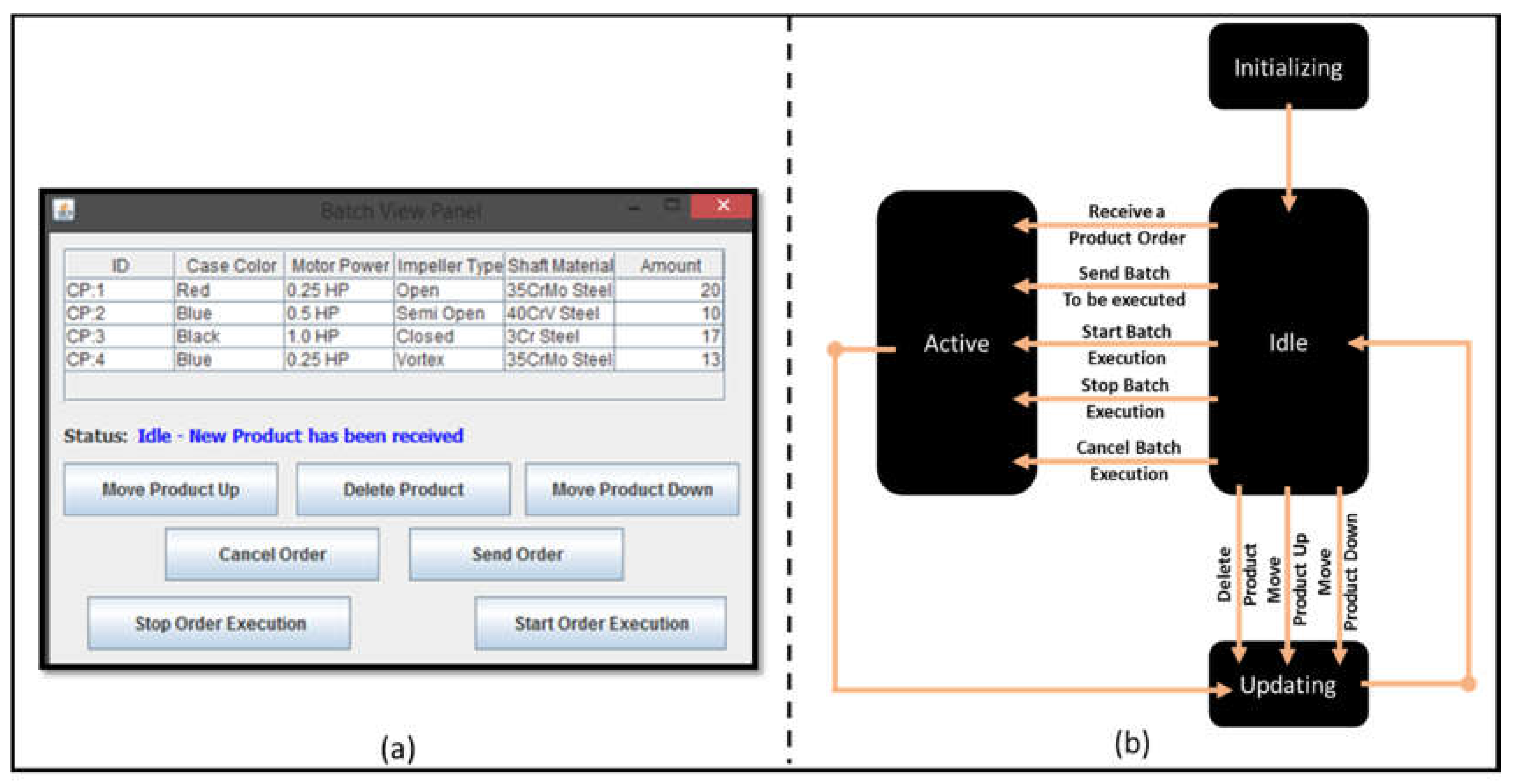
Figure 6a shows a TH interface for a batch order which is contains four different pump orders (CP:1, CP:2, CP:3, CP:4). After initializing the TH interface, the TH goes automatically to the idle-state. The TH is activated if it receives a pump order from the PH, sends a batch order to the SH, or sends start/stop/cancel the batch order execution. The TH returns back to the idle-state after it updates the order list. In idle-state, the pump orders can be rearranged or deleted. Every time the batch order changes, the TH updates itself by passing by the update-state.
5.3. ROH and WOH State-Machines and User Interfaces
Figure 7a shows the OH interface, which can be used to generate different instances of the ROH and/or WOH. After registering an OH, a new UI will be automatically generated as shown in Figure 7b,d. A WOH UI and state machine are shown in Figure 7b,c respectively. After initializing a WOH, it goes automatically to the free-state. The WOH will move to the reserved-state when the SH finds an available and free cooperative IR to load the product order for him. After the IR loads at least one pump for the worker, the WOH will automatically move to the busy-state. The WOH will stay in the busy-state till a task done event is triggered from the WOH UI, therefore it will return back to the free-state. If the worker is temporary outside the workcell–for instance in a break–the WOH can be in non-available-state which is triggered by an away event. When a back event is triggered, the WOH returns back to the free-state. Finally if the worker is permanently outside the workcell–for instance for changing the work shift–the WOH can unregister from the workcell using an unregister event.
An ROH is very similar to a WOH but simpler as it can be seen in Figure 7d,e. The only difference is that the ROH does not have a reserved-state. That is because the SH assigns a product order for one worker and one IR simultaneously in the same instance. Therefore, the IR moves directly to the busy-state to load the product order while the worker is in reserved-state. Then the IR returns back to the free-state.
5.4. SH State-Machine, User Interface, and Control Algorithm
Figure 8a shows the SH interface for a batch order which contains four different pump orders. The different states of the SH can be seen in Figure 8b. The SH goes to the setup-state when it receives a start event from the TH, therefore it starts discovering the available operational resources in the workcell. In the case showed in the figure, two operational resources can be discovered, one of them is Worker_1@HTC_Platform and the other is Robot_1@HTC_Platform. The SH will move to the ready-processing-state if it discovers the existence of at least one worker, at least one IR, and a product order. Otherwise, The SH stays in the idle-state till the three conditions are achieved. In the ready-processing-state, the SH checks the status of all the IRs and the workers and the product orders. The SH will move to ready-assignment-state if three conditions are fulfilled, these conditions are a free available IR, a free available worker, and an available product order. Otherwise, The SH stays in the idle-state till the three condition are achieved.
In the ready-assignment-state, The SH will reserve the first product order in the batch to be executed, and it reserves one available IR and one available worker to assign this reserved product order simultaneously for both of them. During the implementation of this research, we have presumed that the robot takes two minutes to load one product for the worker, therefore in the execution-state, the required time from an IR to execute its task will be two minutes multiplied by the number of products in the assigned product order. Thus, as has been mentioned before, the worker only can start his task after two minutes of the task assignment process, when he has a complete product to assemble. After the worker task done event arrives, the SH will move automatically to the ready-assignment-state to execute the next product order in the batch.
The SH will always go from any current state to the setup-state when a robot/worker registration/deregistration event or a new batch order event arrives. The SH will always go from any current state to the idle-state in the following cases: no worker or robot is available, no batch order is available, or no worker or robot is free. The SH will move from idle-state to ready-processing-state if one robot/worker status changes from free to busy or vice-versa.
5.5. Event Oriented Task Assignment Control
The algorithm which is shown in Figure 9 describes the control mechanism executed by the SH to assign the batch orders to the existing operational resources. When the SH starts, it runs four parallel behaviours. The first behaviour is responsible for continuously discovering and updating the batch order list, this behaviour is always waiting to be triggered by an arrival of a new batch order event. The second behaviour is responsible for continuously discovering and updating the availability of the exciting workers, this behaviour is always waiting to be triggered by an arrival of a new worker registration/deregistration event. The third behaviour is responsible for continuously discovering and updating the availability of the exciting robots, this behaviour is always waiting to be triggered by an arrival of a new robot registration/deregistration event.
The fourth behaviour is responsible for continuously pairing between a free worker and a free robot to assign a batch order for both of them. At the beginning, the behaviour checks start and stop production conditions. If the previous condonations has been achieved, the behaviour checks if there is at least one batch order at the order list. The behaviour uses First Come First Served (FCFS) policy to select the target batch orders. If previous condition has been achieved, the behaviour checks if at least one robot is free. In case if there are more than one free robot at the workcell, the behaviour selects one of them randomly as the target robot. If the previous condition has been achieved, the behaviour checks if at least one worker is free. In case if there are more than one free worker at the workcell, the behaviour selects one of them randomly as the target worker. After achieving all the previous conditions, the behaviour pairs between the target robot and the target worker. After pairing a robot with a worker the algorithm changes their status and then it assigns the task for both of them. The task pairing and assignment will be discussed in details in Section 6.2.
The task assignment event is responsible for triggering this behaviour again. Eventually, all the exciting operational resources will be assigned to an order. Therefore, this behaviour will wait to be triggered again in case of one of the following events arrival: start event, new batch order event, new worker registration event, new robot registration event, worker task done event, and robot task done event.
6. Case Study
The goal of this work is to provide a solution to self-organize the manufacturing process in a W-IR workcell. Putting into consideration the three sources of chaos mentioned in the problem statement section. A centrifugal pump assembly process has been selected as an example of a customized manufacturing process. As it is impossible to show all the variations of the operational resource number within the scope of this paper, we selected a specific case study scenario to show the viability of the solution. The selected case study starts with two workers in cooperation with two IRs, then the number of workers and IRs declines gradually till it reaches to one worker in cooperation with one IR, then the number increases gradually till it reaches again to two workers in cooperation of with two IRs.
At the beginning, the operational resources should register to the workcell. Then the batch should be built and sent to the orchestrator agent (i.e., the supervisor holon) before any interaction happens. During the production execution, a new product order will be updated to the batch list, then it will be executed without any intervention of the manufacturing process.
6.1. Workcell Setup and Batch Order Building
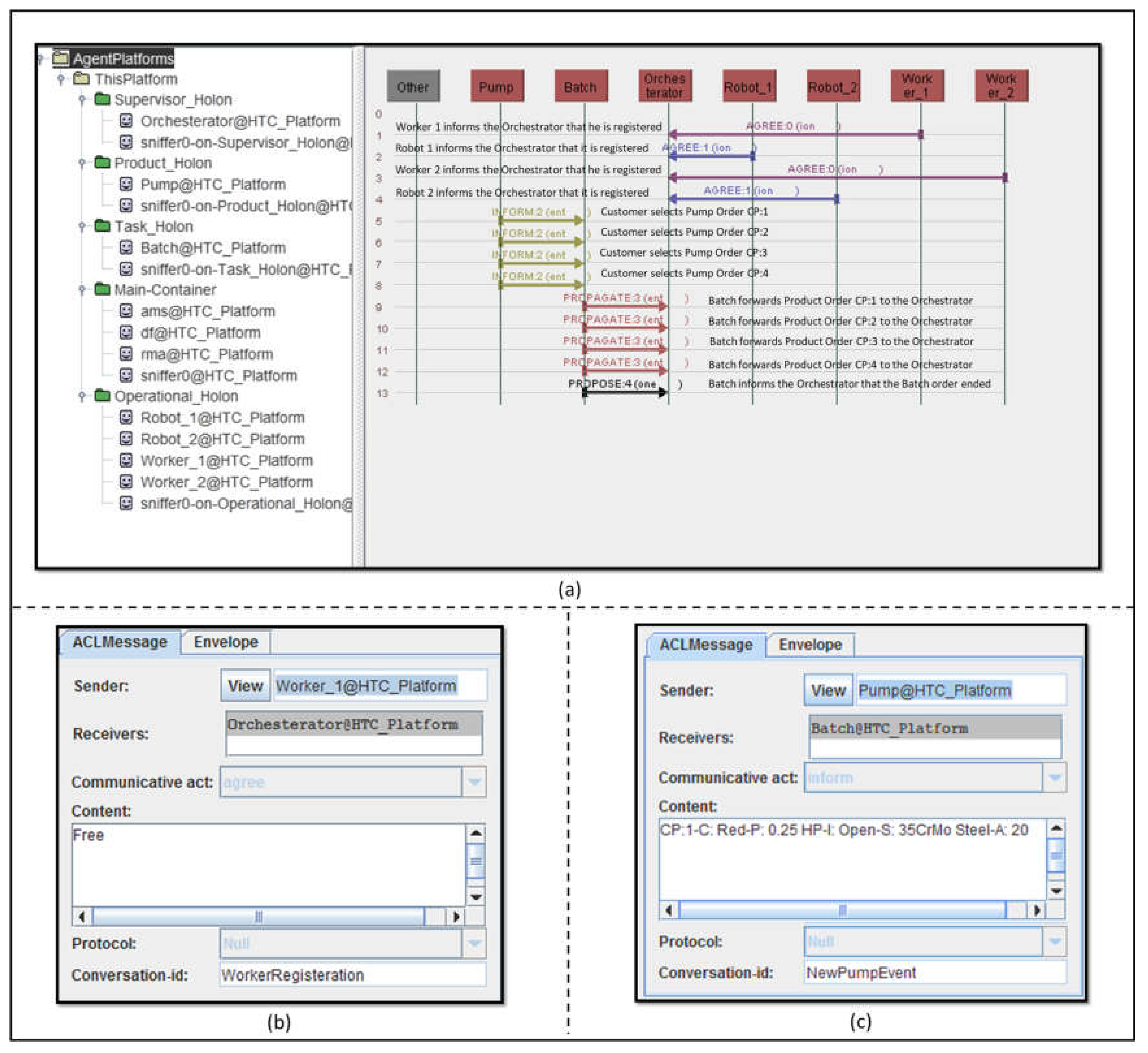
Figure 10 illustrates the interaction between the holons proposed in the case study. This interaction is a result of registering the operational resources into the workcell and building the product orders and the batch list. In the first four lines of Figure 10a, we can see two workers and two IRs are registering sequentially to the operational resources list, by sending an ACL messages with “AGREE” communication act to the orchestrator agent. The orchestrator can distinguish between the AGREE message received from the worker or the robot from the message conversation-id field which can be seen in Figure 10b. For example, a conversation-id “WorkerRegistration” has been used for a worker registering while “RobotRegistration” has been used for a robot registration.
In line 5, 6, 7, and 8 of Figure 10a, we can see four different pump orders with IDs (CP:1, CP:2, CP:3, CP:4) are sent from the pump agent (i.e., the Product holon) to the batch agent (i.e., the Task holon). Each customized pump order is encapsulated in an INFORM message which can be seen in details in Figure 10c. The ACL message content field contains the different features of the pump order CP:1 plus the required quantity. All the pump orders are stored in the batch agent and can be modified and arranged by the TH interface. Then it can be sent to the orchestrator agent as showed in Figure 10a line 9, 10, 11, and 12. The batch agent sent the four customized pump orders in a form of PROPOGATE messages, then it sent a PROPOSE message which is shown in Figure 10a line 13 to indicate the end of this batch order.
6.2. Operation Resources Self-Organizing Interaction
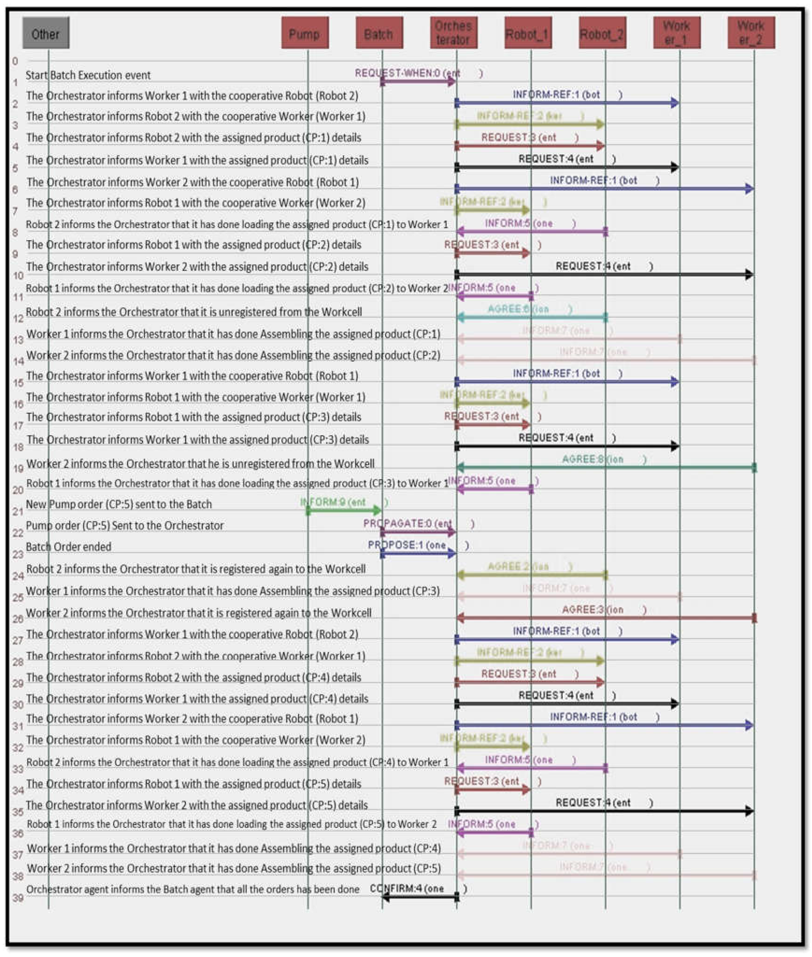
Figure 11 shows the interaction between the available operational resources to manufacture the case study batch order. In the very beginning a start event is sent from the batch order agent to the orchestrator agent in a form of a REQUEST-WHEN message as it can be seen in line 1 of Figure 11. After receiving the start event, the orchestrator agent makes sure that a batch order and the minimum required operational resources exist, therefore the orchestrator agent randomly selects a free pair of one worker and one IR. Then the orchestrator agent is pairing the worker and the IR by sending two INFORM-REF messages for each. In Figure 11 line 2, 3 we can see that the orchestrator agent pairs Worker-1 agent to coordinate with Robot-2 agent. The INFORM-REF message sent to Worker-1 contains the AID address of Robot-2 and vice versa. Then in line 4, 5 of Figure 11 the orchestrator agent sends another two REQUEST messages to Worker-1 and Robot-2 to inform them with the assigned task which in this case is CP:1 order. When CP:1 order is assigned to a robot agent, it will extract the number of pumps in the order and multiplies it by two minutes to calculate the overall time of being in busy-state. While the worker remains in a reserved-state for two minutes starting from the task assignment event. Then the worker goes to a busy-state till it finishes with assembling the CP:1 order.
When the orchestrator agent realizes that the batch order still not finished and available operational resources exist. It pairs between the other free operational resources which in this case are Worker-2 and Robot-1. This pairing can be seen in the INFORM-REF messages which are shown in Figure 11 line 6, 7. An INFORM message is sent from Robot-2 to the orchestrator agent as it can be seen in line 8 of Figure 11, this message expresses that CP:1 order has been already accomplished. The reason that Robot-2 sends this INFORM message is to tell the orchestrator agent to change its status from busy to free. Therefore the orchestrator agent takes Robot-2 into consideration in the next task assignment cycle. The orchestrator agent assigns the CP:2 order to Worker-2 and Robot-1 in line 9,10 of Figure 11 by sending two REQUEST messages to them. Subsequently, Robot-1 tells the orchestrator agent that it has done with loading all the pumps in CP:2 order for Worker-2 as can be seen in line 11 of Figure 11.
An AGREE message sent from Robot-2 to the orchestrator agent can be seen in line 12 in Figure 11, this message tells the orchestrator that Robot-2 has been unregistered from the workcell. The orchestrator understands that this specific AGREE message means a robot deregistration event from the message conversation-id “RobotDeregistration”. Line 13, 14 in Figure 11 show two INFROM messages sent from Worker-1 and Worker-2 respectively to the orchestrator to tell that they have done with assembling CP:1 and CP:2 orders respectively. Then the orchestrator pairs between Robot-1 and Worker-1 as can be seen in line 15, 16 of Figure 11. Then in line 17, 18 of Figure 11 the orchestrator assigns a new order CP:3 for this pair. Worker 2 informs the orchestrator in line 19 of Figure 11 that he is unregistered from the workcell. The orchestrator understands that this specific message means a worker deregistration event from the message conversation-id “WorkerDeregistration”.
In line 20 of Figure 11, Robot-1 tells the orchestrator that it has done with loading all pumps in the CP:3 order to Worker-1. Line 21 in Figure 11 shows a new pump order CP:5 sent from the pump agent to the batch agent via an INFORM message, while line 22, 23 shows sending the pump order from the batch agent to the orchestrator agent. Line 24 in Figure 11 shows an AGREE message sent from Robot-2 to the orchestrator to tell it is registered again to the workcell. Line 25 in Figure 11 shows the INFORM message from Worker-1 to inform the orchestrator that he is done with CP:3 order. Line 26 in Figure 11 shows an AGREE message sent from Worker-2 to the orchestrator to tell he is registered again to the workcell.
Line 27, 28 of Figure 11 show two INFORM-REF messages to pair between Worker-1 and Robot-2, and line 29, 30 of Figure 11 show CP:4 order assignment for this pair. While line 31, 32 of Figure 11 show another two INFORM-REF messages to pair between Worker-2 and Robot-1, and line 34, 35 of Figure 11 show CP:5 order assignment for this pair. An INFORM message sent from Robot-2 to the orchestrator in line 33 of Figure 11 to inform it is done with loading CP:4 order for Worker-1. A similar INFORM message sent from Robot-1 to the orchestrator in line 36 of Figure 11 to inform it is done with loading CP:5 order for Worker-2. Line 37, 38 in Figure 11 show two INFROM messages from Worker-1 and Worker-2 respectively to the orchestrator to tell that they have done with assembling the CP:4 and CP:5 orders. Finally the orchestrator sends a CONFIRM message to the batch agent to indicate the end of the execution of the given batch order.
6.3. Workcell Peformance Measures
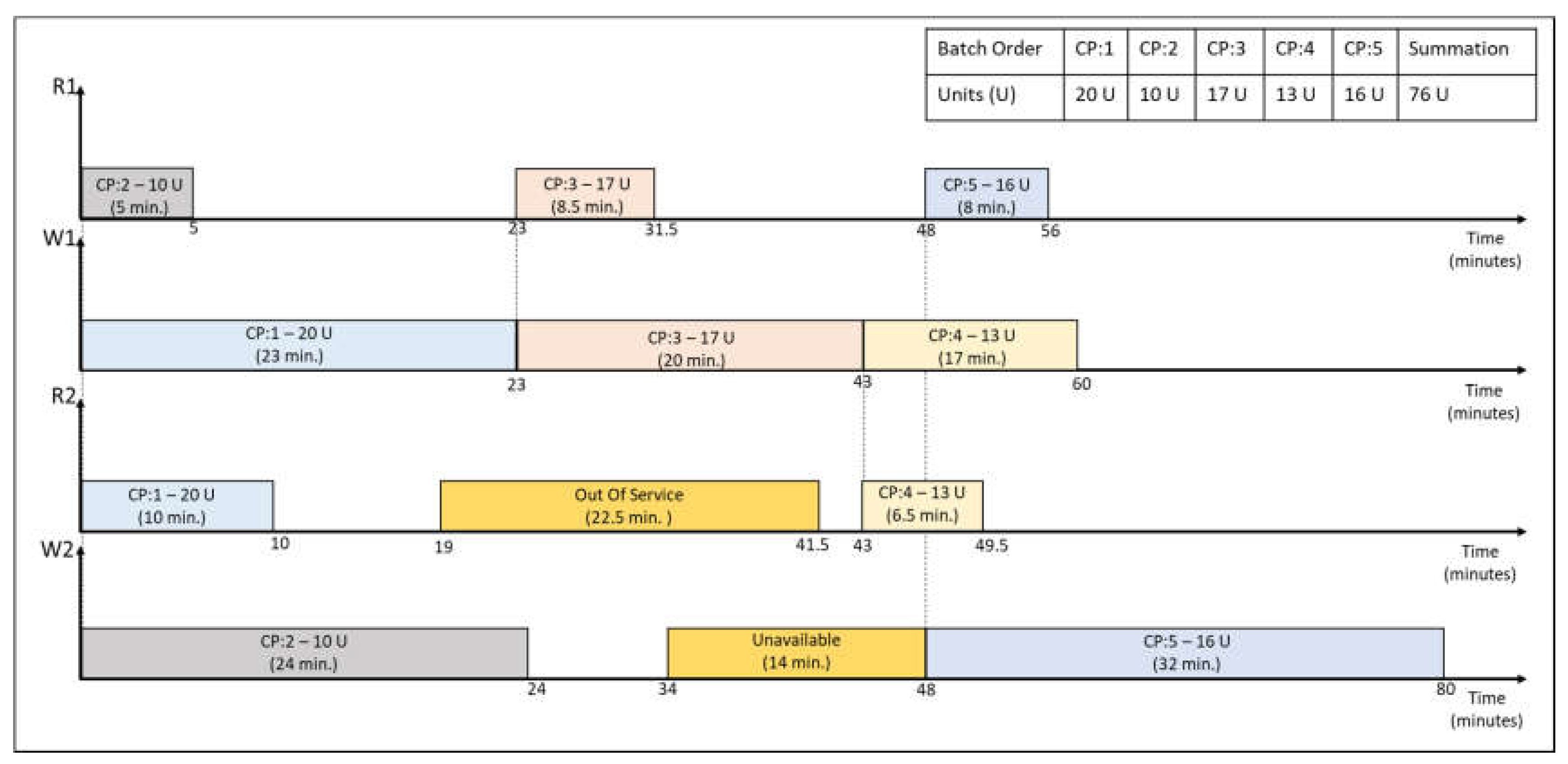
By definition the makespan is the total amount of time required to complete a group of jobs. In our case study we have five batch orders with an overall of 76 pump unit. The overall makespan of all the batch orders can be easily seen in Figure 12 which equals to 80 min. Table 1 is analyzing the different measurements which can be implied from Figure 12. The availability measure can be seen at the first row of Table 1. The availability is measuring the actual time which the operational resource is available to operate at the workcell with respect to the makespan. As it can be seen from the table, worker-1 and robot-1 were available all over the makespan. While worker-2 and robot-2 were available only 82.5%, and 71.9% of the makespan respectively.
The idle period is the time when an operational resource is available but waiting for a task assignment. Apparently worker-2 was the least idle operational resource, while robot-1 was the most idle. The productivity of an operational resource is the number of units an operational resource produced with respect to the allover number of units produced by the workcell. It can be seen that worker-1 has higher productivity than worker-2, and robot-1 has higher productivity than robot-2. The final measuring factor is the average production rate. This measuring factor expresses how many units the operational resource produces per minute. As it has been mentioned before, this factor has been assumed to be constant for the robot however it is variable for the worker. It can be seen that worker-1 is much faster than worker-2, as the production rate of worker-1 can be rounded to 2.5 unit per minute while it is around 1.0 unit per minute for worker-2.
7. Discussion, Conclusions, and Future Work
In this paper, we presented the idea of the cooperative work between the human worker and the IR, as a novel method which promotes the reconfigurable manufacturing techniques. Considering three important questions which are: the variation in the number of the operation resources, the variation in the production customization level and volume, and finally the variation in the time taken from the workers to accomplish a task. Therefore, the problem of the W-IR workcell self-organization became the main focus of this paper.
Evolving the ADACOR control architecture by merging it to the ISA-95 standard, generated the solution concept. The solution concept has been implemented using JADE framework. The fact that the four different holon categories of ADACOR can have many customized instances, solved the first two questions proposed by the paper. For instance during the case study scenario, different instances of the WOH or the ROH could register to or unregister from the workcell, without interrupting the manufacturing process. Therefore, the concept of “Plug and Operate” has been totally fulfilled. Moreover, when different customized instances of the PH were introduced during any time of the production process, the solution was able to match the existing operation resources to the required production order. Therefore, the concept of “Customize and Produce” has been totally fulfilled. Finally, The state machine of the SH was able to monitor all the state machines of the other three holons. This answers the last question proposed in the problem statement, by giving the SH the capability of assigning the tasks to the operation resources based on variable time windows. Therefore, the concept of “Assign and Monitor” can be achieved.
By analyzing the case study performance measures, we can see the correlation between the availability of the operational resources and their idle periods. Since the value of the idle period is increasing whenever the operational resource is more available. Also we can spot a relation among the productivity, the average production rate, and the availability of an operational resource. Thus the value of productivity is increasing due to the increasing in the operational resource production rate and availability, Inasmuch as it is logical to produce more units if you are more available and have high production rate. This relation can be seen between worker-1 and worker-2, since worker-1 was available for 100% of the makespan and has a production rate of 2.48 U./Min, therefore his productivity was 65.8%. While worker-2 was available for 82.5% of the makespan and has a production rate of 0.92 U./min, therefore his productivity was 34.2%. Even robot-1 and robot-2 have the same production rate, the influence of the availability on the average production rate can be seen. As robot-1 was available for 100% while robot-2 was available for 71.9% of the makespan, therefore robot-1 has a productivity of 56.6% while robot-2 has a productivity of 43.4%. Analyzing the workcell measures gives an impression that the proposed solution tries to optimize the distributability of the task assignment with respect to the availability and the production rate of the operational resources. Since the solution tends to compensate the fact that the production rate of the workers is variable and unknown, by continuously checking the availability and the status of them therefore it can assign the tasks based on those two factors. The same idea is applied to the robots as well, if that they have variable production rates and due to their availability over the workcell.
Even the proposed case study scenario only showed two workers in cooperation with two IRs, it proves how sophisticated and chaotic in terms of information control the W-IR cooperation could be. However the proposed control solution was completely able to accomplish the research goals, and providing the highest efficiency of using the time of the operational resources.
During the future work, a cooperative IR hardware will be connected to the solution model as well as a worker UI hardware. The supervisor holon responsibility will be extended to provide the coordination with other W-IR workcells. Moreover Level-4 of ISA-95 standard which concerns the business planning should be added to the solution concept.
Acknowledgments
This research has been supported by the German Federal State of Macklenburg-Western Pomerania and the European Social Fund under grant ESF/IV-BM-B35-0006/12 and by grants from University of Rostock and Fraunhofer IGD.
Author Contributions
Ahmed R. Sadik conceived the implementation and the analysis of the case study and studied the interaction; Bodo Urban conceived the research concept and the problem statement.
Conflicts of Interest
The authors declare that there is no conflict of interest.
References
- Goodrich, M.; Schultz, A. Human-Robot Interaction: A Survey. Found. Trends. Hum. Comput. Interact. 2007, 1, 203–275. [Google Scholar] [CrossRef]
- Pinker, S. How the Mind Works, 1st ed.; Norton: New York, NY, USA, 1997; pp. 119–127. [Google Scholar]
- Buizza, G.; Ceriani, N.; Zanchettin, A.; Rocco, P.; Bascetta, L. Safety Control of Industrial Robots Based on a Distributed Distance Sensor. IEEE Trans. Control. Syst. Tech. 2014, 22, 2127–2140. [Google Scholar] [CrossRef]
- Lasota, A.; Rossano, F.; Shah, A. Safe Close-Proximity Human-Robot Interaction with Standard Industrial Robots. In Proceedings of the IEEE International Conference on Automation Science and Engineering (CASE), Taipei, Taiwan, 18–22 August 2014. [Google Scholar]
- Elmaraghy, H.A. Flexible and reconfigurable manufacturing systems paradigms. Int. J. Flex. Manuf. Syst. 2005, 17, 261–276. [Google Scholar] [CrossRef]
- Kruger, K.; Basson, A. Multi-Agent Systems vs IEC 61499 for Holonic Resource Control in Reconfigurable Systems. In Proceedings of the Forty Sixth CIRP Conference on Manufacturing Systems, Setubal, Portugal, 29–30 May 2013; Volume 7, pp. 503–508. [Google Scholar]
- Black, G.; Vyatkin, V. Intelligent Component-Based Automation of Baggage Handling Systems with IEC 61499. IEEE Trans. Autom. Sci. Eng. 2008, 7, 699–709. [Google Scholar] [CrossRef]
- Michalos, G.; Makris, S.; Spiliotopoulos, J.; Misios, I.; Tsarouchi, P.; Chryssolouris, G. ROBO-PARTNER: Seamless Human-Robot Cooperation for Intelligent Flexible and Safe Operations in the Assembly Factories of the Future. Procedia CIRP 2014, 23, 71–76. [Google Scholar] [CrossRef]
- Tsarouchi, P.; Matthaiakis, A.; Makris, S.; Chryssolouris, G. On a human-robot collaboration in an assembly cell. Int. J. Comput. Integr. Manuf. 2016, 30, 580–589. [Google Scholar] [CrossRef]
- Koestler, A. The Ghost in the Machine, 1st ed.; Macmillan: New York, NY, USA, 1968. [Google Scholar]
- Botti, V.; Giret, A. Holonic Manufacturing Systems. In ANEMONA—A Multi-Agent Methodology for Holonic Manufacturing Systems, 1st ed.; Springer: London, UK, 2008; pp. 7–20. [Google Scholar]
- Van Brussel, H.; Wyns, J.; Valckenaers, P.; Bongaerts, L.; Peeters, P. Reference architecture for holonic manufacturing systems: PROSA. Comput. Ind. 1998, 37, 255–274. [Google Scholar] [CrossRef]
- Babiceanu, R.; Chen, F. Development and Applications of Holonic Manufacturing Systems: A Survey. J. Intell. Manuf. 2006, 17, 111–131. [Google Scholar] [CrossRef]
- Leitão, P.; Restivo, F. ADACOR: A holonic architecture for agile and adaptive manufacturing control. Comput. Ind. 2006, 57, 121–130. [Google Scholar] [CrossRef]
- Leitão, P.; Restivo, F. Implementation of a Holonic Control System in a Flexible Manufacturing System. IEEE Trans. Syst. Man Cybern. Part C Appl. Rev. 2008, 38, 699–709. [Google Scholar] [CrossRef]
- Bussmann, S. An agent-oriented architecture for holonic manufacturing control. In Proceedings of the 1st international workshop on Intelligent Manufacturing Systems, Lausanne, Switzerland, 15–17 April 1998; pp. 1–12. [Google Scholar]
- Sadik, A.; Urban, B. A Holonic Control System Design for a Human & Industrial Robot Cooperative Workcell. In Proceedings of the 2016 International Conference on Autonomous Robot Systems and Competitions (ICARSC), Bragança, Portugal, 4–6 May 2016; pp. 118–123. [Google Scholar]
- Jennings, N.; Wooldridge, M. Agent Technology, 1st ed.; Springer: Berlin, Germany, 1998; pp. 3–28. [Google Scholar]
- Shen, W.; Hao, Q.; Yoon, H.; Norrie, D. Applications of agent-based systems in intelligent manufacturing: An updated review. Adv. Eng. Inform. 2006, 20, 415–431. [Google Scholar] [CrossRef]
- Jade Site. Available online: http://jade.tilab.com/ (accessed on 8 January 2017).
- Bellifemine, F.; Caire, G.; Greenwood, D. Developing Multi-Agent Systems with JADE, 1st ed.; Wiley: Chichester, UK, 2008. [Google Scholar]
- FIPA Site. Available online: http://www.fipa.org/ (accessed on 1 February 2017).
- Poslad, S. Specifying protocols for multi-agent systems interaction. ACM Trans. Auto. Adapt. Syst. 2007, 2, 1–15. [Google Scholar] [CrossRef]
- Black, G.; Vyatkin, V. Intelligent Component-Based Automation of Baggage Handling Systems With IEC 61499. IEEE Trans. Autom. Sci. Eng. 2010, 7, 337–351. [Google Scholar] [CrossRef]
- Teahan, W. Artificial Intelligence–Agent Behaviour, 1st ed.; BookBoon: London, UK, 2010. [Google Scholar]
- Govindaraju, R.; Putra, K. A methodology for Manufacturing Execution Systems (MES) implementation. In Proceedings of the IOP Conference Series: Materials Science and Engineering, Kuala Lumpur, Malaysia, 12–14 November 2015; Volume 114, pp. 12–94. [Google Scholar]
- Ohnsson, C.; Brandl, D.; Unger, K. White Paper ISA 95 for Beginners; WBF: Longwood, FL, USA, 2006. [Google Scholar]
- García-Domínguez, A.; Marcos-Barcena, M.; Medina-Bulo, I.; Prades, L. Towards an Integrated SOA-Based Architecture for Interoperable and Responsive Manufacturing Systems Using the ISA-95 Object Model. Key Eng. Mater. 2014, 615, 145–156. [Google Scholar] [CrossRef]
- Hernández-Martínez, E.; Puga-Velazquez, E.; Foyo-Valdés, S.; Meda Campaña, J. Task-based Coordination of Flexible Manufacturing Cells using Petri Nets and ISA standards. IFAC-PapersOnLine 2016, 49, 1008–1013. [Google Scholar] [CrossRef]
Figure 1.
(a) ADACOR (ADAptive holonic COntrol aRchitecture) Model; (b) Holon Generic Structure.
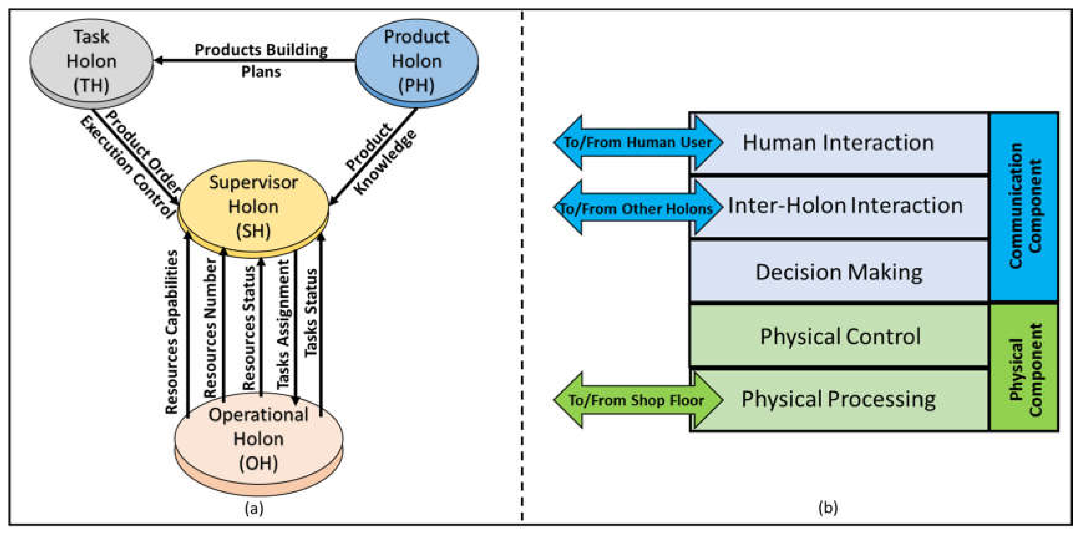
Figure 2.
Java Agent Development (JADE).
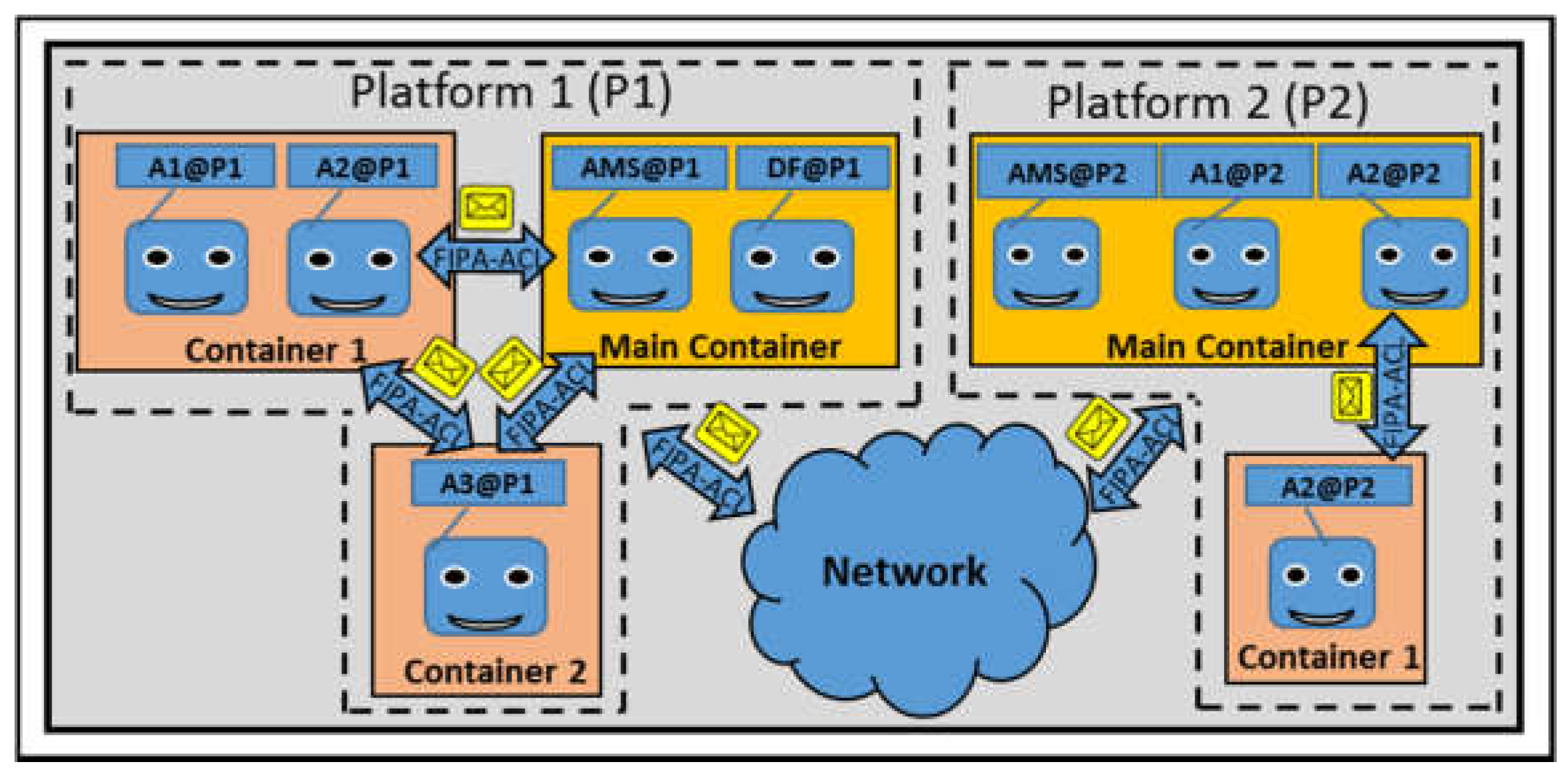
Figure 3.
ANSI/ISA-95 Standard Architecture.
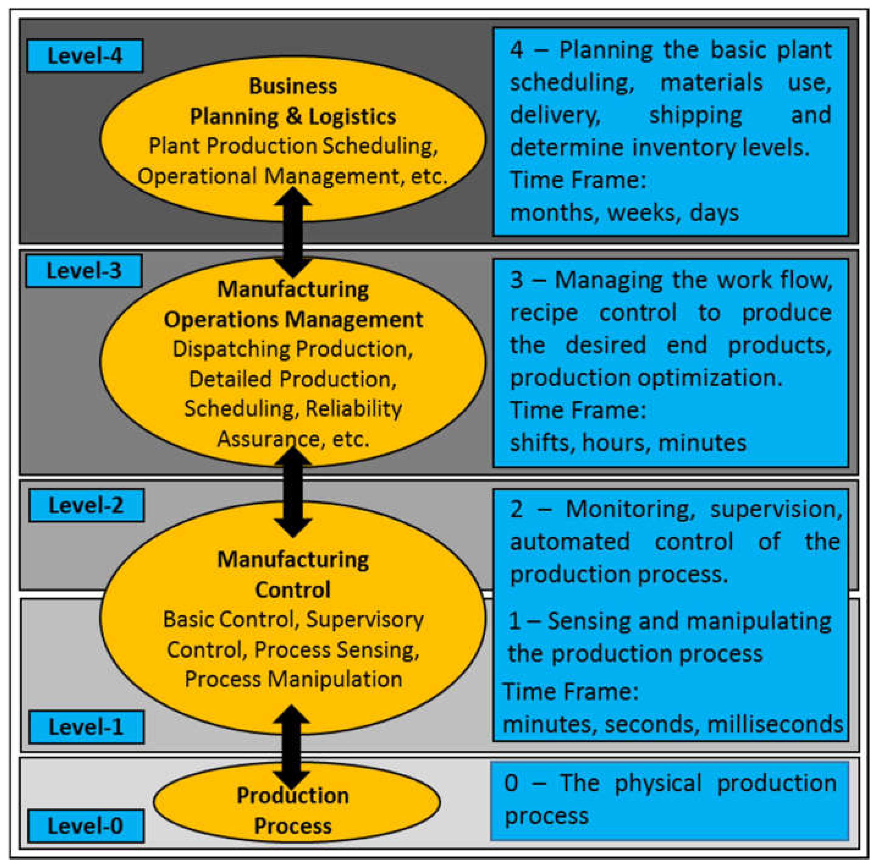
Figure 4.
Combined ADACOR and ISA-95 Conceptual Model.
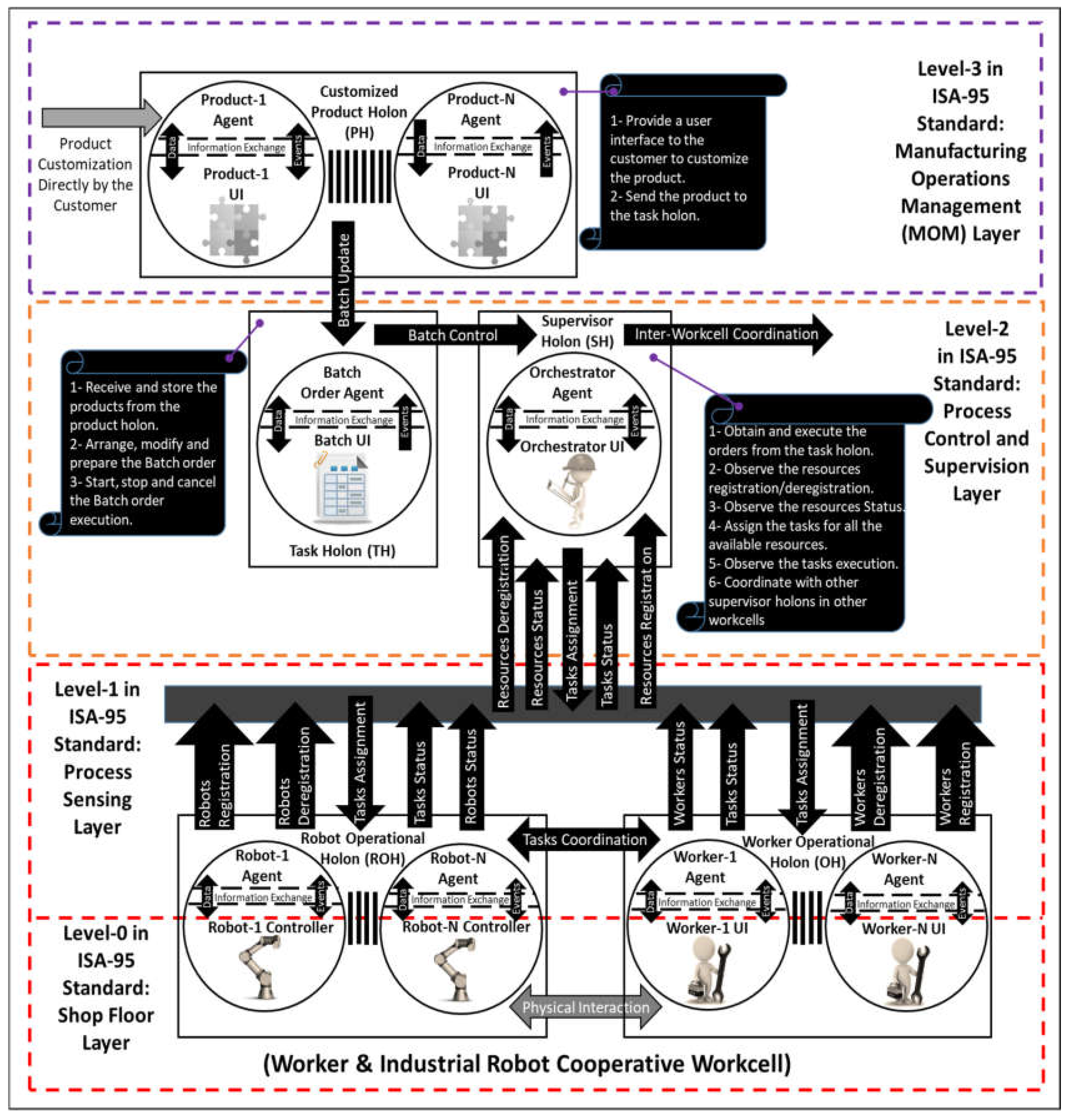
Figure 5.
(a) PH (Product Holon) User Interface; (b) PH State-Machine.
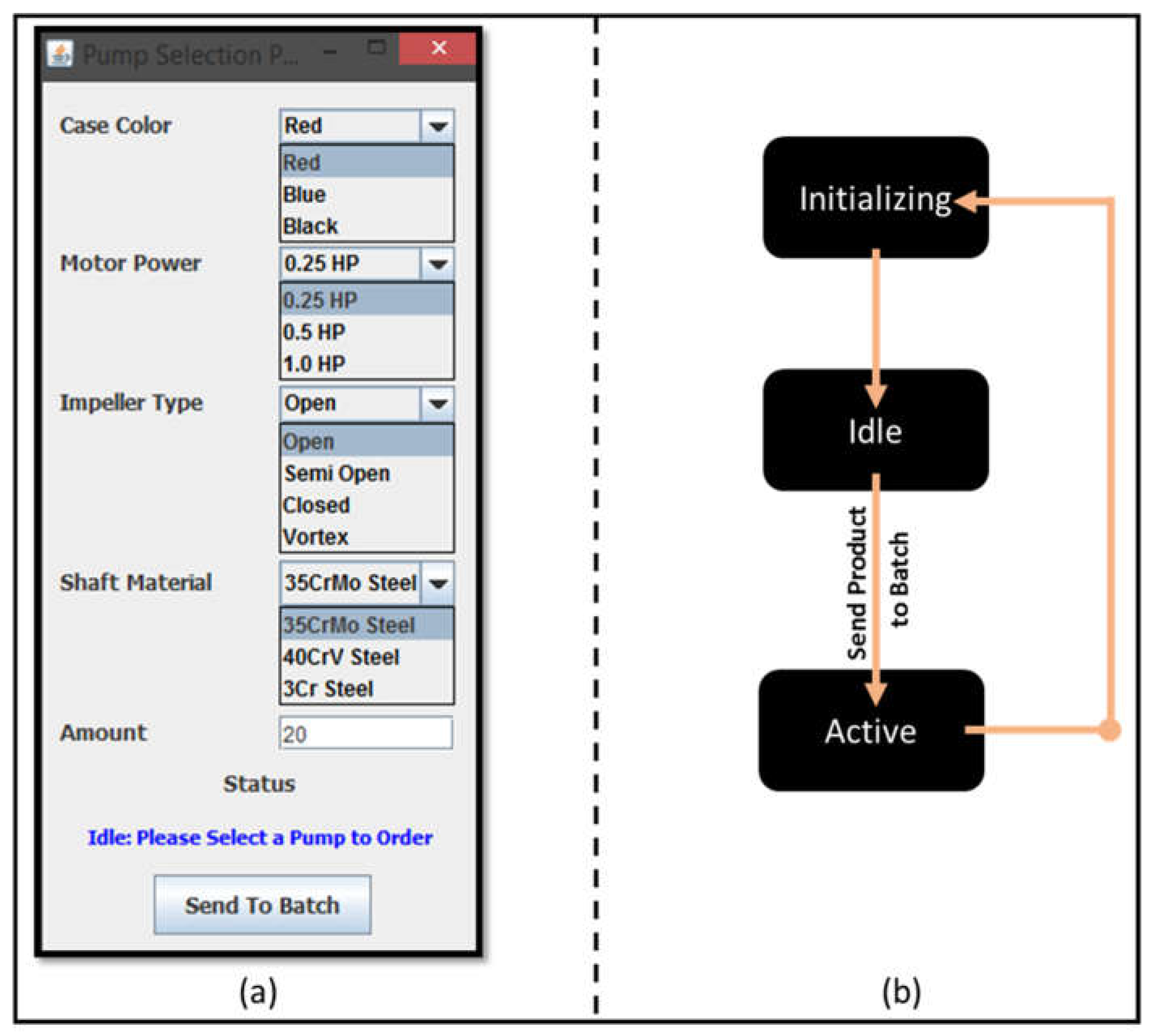
Figure 6.
(a) TH (Task Holon) User Interface; (b) TH State-Machine.

Figure 7.
(a) OH (Operational Holon) User Interface; (b) ROH (Robot Operational Holon) User Interface; (c) ROH State-Machine; (d) WOH (Worker Operational Holon) User Interface; (e) WOH State-Machine.
Figure 7.
(a) OH (Operational Holon) User Interface; (b) ROH (Robot Operational Holon) User Interface; (c) ROH State-Machine; (d) WOH (Worker Operational Holon) User Interface; (e) WOH State-Machine.
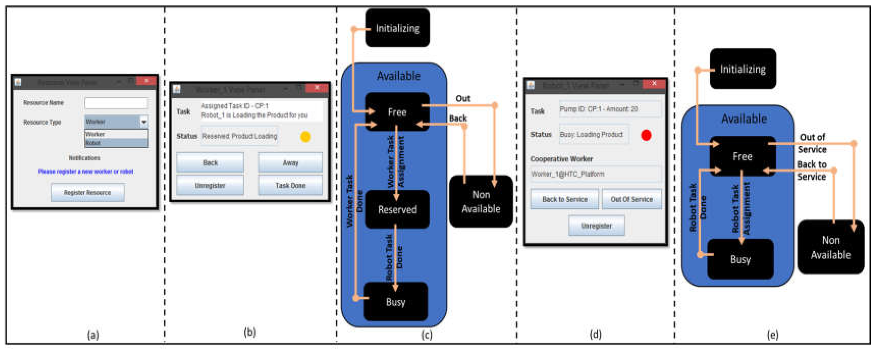
Figure 8.
(a) SH (Supervisor Holon) User Interface; (b) SH State-Machine.
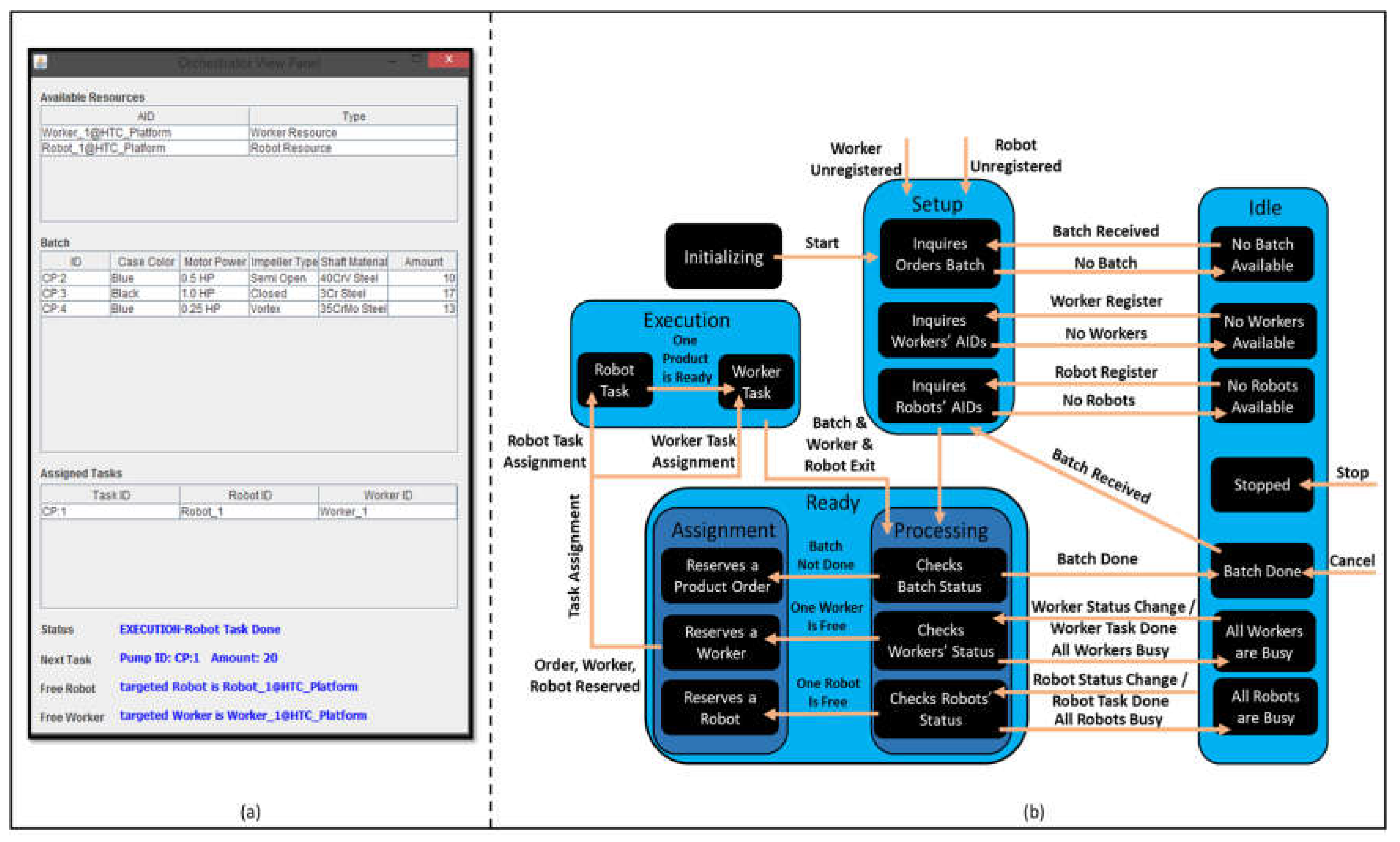
Figure 9.
SH Task Assignment Control Algorithm.

Figure 10.
(a) Workcell Setup and Batch Order Building; (b) ACL Message holds the Worker Registration; (c) ACL Message holds the product details.
Figure 10.
(a) Workcell Setup and Batch Order Building; (b) ACL Message holds the Worker Registration; (c) ACL Message holds the product details.

Figure 11.
Operational Resources Interaction to Execute the Case Study.

Figure 12.
Case-study Gantt Chart.


Table 1.
Operational Resources Performance.
| Items | Worker-1 | Worker-2 | Robot-1 | Robot-2 |
|---|---|---|---|---|
| Availability | ||||
| Idle Period | ||||
| Productivity | ||||
| Average Production Rate |
© 2017 by the authors. Licensee MDPI, Basel, Switzerland. This article is an open access article distributed under the terms and conditions of the Creative Commons Attribution (CC BY) license (http://creativecommons.org/licenses/by/4.0/).
Share and Cite
MDPI and ACS Style
Sadik, A.R.; Urban, B. Combining Adaptive Holonic Control and ISA-95 Architectures to Self-Organize the Interaction in a Worker-Industrial Robot Cooperative Workcell. Future Internet 2017, 9, 35. https://doi.org/10.3390/fi9030035
AMA Style
Sadik AR, Urban B. Combining Adaptive Holonic Control and ISA-95 Architectures to Self-Organize the Interaction in a Worker-Industrial Robot Cooperative Workcell. Future Internet. 2017; 9(3):35. https://doi.org/10.3390/fi9030035
Chicago/Turabian StyleSadik, Ahmed R., and Bodo Urban. 2017. "Combining Adaptive Holonic Control and ISA-95 Architectures to Self-Organize the Interaction in a Worker-Industrial Robot Cooperative Workcell" Future Internet 9, no. 3: 35. https://doi.org/10.3390/fi9030035
Note that from the first issue of 2016, this journal uses article numbers instead of page numbers. See further details here.