Extensions and Enhancements to “the Secure Remote Update Protocol”


Faculty of Engineering and the Environment, University of Southampton, Burgess Road, Southampton, S016 7QF, UK
*
Author to whom correspondence should be addressed.
Future Internet 2017, 9(4), 59; https://doi.org/10.3390/fi9040059
Submission received: 31 August 2017
/
Revised: 26 September 2017
/
Accepted: 27 September 2017
/
Published: 30 September 2017
(This article belongs to the Special Issue IoT Security and Privacy)
Abstract
:This paper builds on previous work introducing the Secure Remote Update Protocol (SRUP), a secure communications protocol for Command and Control applications in the Internet of Things, built on top of MQTT. This paper builds on the original protocol and introduces a number of additional message types: adding additional capabilities to the protocol. We also discuss the difficulty of proving that a physical device has an identity corresponding to a logical device on the network and propose a mechanism to overcome this within the protocol.
1. Introduction
In our original paper [1], we presented the Secure Remote Update Protocol (SRUP), a Command and Control (C2) protocol for Internet of Things devices, and focused on how the protocol can be used to implement a robust and secure software update. In this paper, we introduce additional message types to expand the functionality of the protocol and, in particular, address the challenging problem of the identity of devices.
Section 3 introduces enhancements to the originally published protocol to address some identified short-comings. Section 4 identifies the challenges of, and a proposed solution for, initial key exchange within an Internet of Things (IoT) system. Section 5 looks at proof of identity in the context of the IoT and SRUP. Section 6 looks at the challenges of key revocation, and Section 7 describes some potential attacks against the system and mitigations against these. Section 8 describes a technique for making human recognition of cryptographic identities more straightforward. Finally, Section 9 describes testing of the initial implementation of the protocol and planned future experimentation.
2. Background
With the proliferation of IoT devices seen over the last few years, such devices have been the targets of those wishing to create networks of slave devices (so-called botnets, such as the one created by the Mirai malware [2]), with which to stage Distributed Denial of Service (DDoS) attacks. These attacks typically exploit serious security vulnerabilities in the design of many IoT devices, such as hard-coded passwords, lack of security updates to the device software and insecure network configuration (such as providing remote network terminal interfaces) [3]. The key motivation behind SRUP was to provide a secure and trustworthy mechanism for remote C2 operations on IoT devices; whilst reducing the attack surface to the minimum.
The Secure Remote Update Protocol has been designed to exploit extant commodity open-source software and open standards. It takes advantage of existing and commonly-used protocols and techniques for Internet communications, but combines them in a unique and novel way to provide an integrated protocol to conduct C2 operations for IoT devices, autonomous systems and other related platforms.
There are a number of communications architectures used to facilitate communications with IoT devices; one of the most commonly used is the publish/subscribe paradigm. Within IoT devices, perhaps the most commonly-used publish/subscribe protocol is Message Queuing Telemetry Transport (MQTT).
MQTT is a lightweight brokered publish/subscribe protocol, originally developed by Andy Stanford-Clark (IBM) and Arlen Nipper (Arcom) in 1999 to provide lightweight telemetry for the oil and gas industry. It became an Organization for the Advancement of Structured Information Standards (OASIS) standard in 2013 [4]. All messages sent are routed via a broker; the broker is responsible for tracking all subscriptions and sending data to subscribers when a publisher issues a message. MQTT runs over Internet Protocol Suite (TCP/IP) networks, using Transmission Control Protocol (TCP) [5] as the transport layer.
MQTT supports multiple Quality of Service (QoS) settings. For the minimum overhead, QoS 0 (defined by the MQTT standard [4] as “at most once” delivery) can be used, which provides no guarantee of delivery. However, for many IoT applications, especially those deployed in locations with austere or otherwise fragile Internet connectivity, QoS 1 (“at least once” delivery) provides an excellent way to ensure that C2 messages are sent/received, at the cost of a slightly higher data overhead. QoS 1 requires the MQTT to acknowledge all received messages, using a Publish Acknowledge (PUBACK) message. MQTT also supports QoS 2 (“exactly once” delivery), albeit at the cost of requiring a three-part message exchange within MQTT. Given the nature of the SRUP messages and the enhancements introduced in Section 3, this level of assurance is not required. Both QoS 1 and 2 are implemented at the MQTT level and carried out automatically by the MQTT client; so that different QoS may be implemented in different situations without needing to make any changes at the SRUP level.
MQTT is by default an insecure protocol (all data are sent as plain text), but it can be secured with the application of Transport Layer Security (TLS) [6] to the traffic.
There are a number of open-source brokers; this research has been carried out using the Mosquitto broker. Mosquitto implements the MQTT protocol Versions 3.1 and 3.1.1 [7].
MQTT is a very widely-supported protocol within the IoT. MQTT libraries exist for many common development platforms (including Arduino and mbed); and it is supported by the vast majority of programming languages. There is also a large number of clients available, both command-line tools and GUI applications. There are a number of clients available for mobile devices, as well, including clients for both iOS and Android. MQTT is also the protocol used by Amazon Web Services (AWS) for their IoT platform.
SRUP is built on top of MQTT and provides an efficient binary message structure contained within the payload of an MQTT message. SRUP has been designed as a messaging protocol for C2 messages for the IoT that assures both authentication of the origin of a message and integrity of the content.
3. Enhancements and Improvements to the Original Protocol
3.1. Vulnerability to Replay Attack
The initially specified version of the SRUP protocol provides a good degree of security against a malicious party changing or spoofing the C2 messages that are being sent to the device. By using cryptographic signatures, applied over all of the data contained within the SRUP message, any part of the data that is altered will cause the signature to fail to validate against the content of the message. In the context of software update, further assurance is provided by including the output from a secure hashing function (SHA-256), to validate the integrity of the file to be retrieved.
There is, however, a potential vulnerability that remains in the implementation: namely potential susceptibility to “replay attack”. A replay attack is one where a malicious party captures a message and re-transmits it at a future time in order to make the receiving device perform the previous operation again. In the case of the initial implementation of SRUP (which only implemented the update message-set), there is a relatively low risk associated with this: the attacker would only be able to make the device download a valid update. However, with patience, after capturing an initial update message and after detecting a second update, it would in theory be possible to roll the device back to a previous version. It may also be possible to use this mechanism to stage a denial-of-service attack against a specific device by constantly sending it messages forcing it to apply the same update (and potentially taking it off-line whilst it did so). Clearly, as the protocol grows to add different classes of message, the potential damage of a message being replayed to a device is much higher.
3.1.1. Common Mitigations to Replay Attack
A common solution to replay attacks is to introduce an additional one-time nonce element within the communication (for example, as used within Hyper-Text Transfer Protocol (HTTP) ‘Basic’ authentication [8,9]), such that a reply to one message will not be valid when sent in conjunction with another. However due to the model of minimal interaction that is used by SRUP, this approach will not work without at least two more messages being exchanged. For example, after the existing initialized message (sent to the device with the server’s session token), the device would need to send an initial response message (containing the session token and a unique device token), and the server would then respond with a second message confirming the initiation (containing both tokens). This goes against the design concept for SRUP to minimize the communications overhead, especially for devices with poor-quality network connections.
Another commonly-adopted solution is to introduce an accurate time-stamp (this is an approach used by Kerberos Network Authentication [10]); but this requires that all devices have access to a very accurately synchronized time-signal (potentially very challenging when considering communications via austere data networks).
A simpler solution that might be adopted in the context of SRUP would be to require each device to keep a log of all of the tokens that they have received (restricted to only the tokens contained within validly signed messages to prevent a brute force attack from overwhelming the storage) and to require that the device check that any new token received does not match one that has been previously received. SRUP uses a Boost Universally Unique Identifier (UUID) [11] for session tokens: 128 bits in length and guaranteed to be unique for a given instance of the server. A receiving device would therefore need to store (a potentially large number of) received tokens in persistent memory in order to prevent the list from being reset by forcing the device to power-cycle.
This approach is not well suited to real-world use, as the storage overhead is potentially very significant. Each token is 16 bytes, so even before considering any storage overhead, 512 tokens would consume 8 kb of storage. For an embedded device without a file-system, this would potentially require the use of an EEPROM module (such modules typically provide 64–512 kb: equivalent to just 4096–32,768 tokens).
3.1.2. A Sequence ID-Based Approach
The proposed method to address replay attack within SRUP is to use a sequence ID-based approach: similar in concept to that used within the LoRaWAN protocol [12]. Adopting this method would require an additional value (a sequence ID) within all SRUP messages. A 64-bit (eight byte) sequence ID would be more than sufficient for this purpose (64 bits would permit a system using 1,000,000 messages a second to run for over 580,000 years before overflow). In order to conserve space in the SRUP message, it might appear to be preferable to adopt a smaller size (e.g., a six byte sequence ID, which would still permit 100,000 messages/second for 89 years). However, since a six-byte integer is not a standard size, we would be required to implement our own six-byte integer type to handle this value, and although this could be easily done in most languages, given that for even the smallest message type, the difference would make a <1% difference to the overall message size, it is felt that there is no value in doing this vs. using a standard 64-bit integer (e.g., uint64_t or unsigned long long) for the sequence ID.
The implementation would work in the same way for messages sent by the server and messages sent by the devices. In all cases, the sender would simply store the last value it used to communicate with that receiver, in local persistent storage, and increment it by one for each new message.
A typical device implementation would require that the device stores the last value that it has received from that server, and the protocol would require that any message received from a given server has a sequence ID greater than the last received sequence ID from that server. Any message received where the sequence ID is less than or equal to a previously received sequence ID should be discarded.
Since under the SRUP paradigm, devices can only accept messages from a server (the protocol does not support peer-to-peer messaging), devices would be required to store (within persistent storage such as a file system or EEPROM) just one such value for each server with which the device is in communication. The relatively small size of the sequence ID means that even devices implemented using tiny microcontroller-based hardware would be unlikely to face storage limitations. For example, just one kilobyte of storage is more than sufficient for 128 sequence IDs at 64 bit (and it is expected that 128 different active C2 servers at any given time is likely significantly in excess of any requirement from any real-world application).
On the server side, it can be assumed that storage will be much less of an issue. This approach would require that a server keeps the last sequence ID from all devices that they have communicated with (until such a time that the device has been removed from the system). Even a server with 100,000,000 devices would require less than 800 Mb of storage for the current sequence IDs; a relatively trivial amount for any cloud-based server implementation.
The SRUP protocol has been updated to incorporate an eight-byte (64 bit) sequence ID value for all message types; and to require that all received SRUP messages must be rejected if the sequence ID is not strictly greater than the last received sequence ID from that sender.
3.2. Activate Confirmation
In the original protocol specification, no provision was made for a server to request confirmation that a device had successfully received and acted upon the SRUP_ACTIVATE message; rather, it was assumed that the server would be able to identify that the activation had occurred via other (non-protocol) means. For completeness of the protocol, this capability has now been added.
Whilst this could be done by adding an additional message-type (for example a type such as SRUP_MESSAGE_TYPE_ACTIVATE_RESPONSE), such a message-type would however have a structure identical to the existing SRUP_MESSAGE_TYPE_RESPONSE; so a more elegant solution would be to use the existing message-type, but to add two new responses to the previously defined statuses. This approach has been adopted in the revised version of the protocol.
In keeping with other enhancements to the protocol, which seek to minimize the number of different message types required, this approach helps to keep the protocol as simple as possible to implement, whilst providing all of the functionality it requires.
3.3. Sender ID
In the original description of SRUP, it was assumed that there was no requirement to communicate details of the sender of a given message, since the centralised nature of the protocol meant it would always either correspond to a message from a server to a device, or from a device to a server. The identity of the device would be contained within the MQTT topic that the message was sent over; and it was assumed that a device receiving a message could safely assume that it came from the server.
The paradigm of using the MQTT topic to convey the source/destination information means that no additional data need be consumed in sending this as a part of the messages. However in the event that multiple C2 servers are used simultaneously, there is no way for a device receiving a message to know which server has sent the message and, therefore, against which public key the signature should be verified.
There are three potential solutions to this problem. The simplest is that the receiver should try each of the keys it has in turn before concluding that the message cannot be verified. This is however neither a scalable nor an elegant solution, and so, it can be rejected.
Another alternative is to further use the MQTT topic hierarchy to signify the sender. For example, rather than subscribing to SRUP/dev0x01, the device and server(s) could subscribe to SRUP/dev0x01/# (using the MQTT topic wildcard character #). This would then enable messages from the device to use the higher level topic and for messages from different servers to use subtopics (e.g., SRUP/dev0x01/sv0x2F) to indicate their origination. The topic field of the MQTT message could then be parsed by the receiving device to extract the sender identity.
The third method is to include an additional field within the base SRUP message (i.e., the part that is common to all messages, consisting of the header, sequence ID, signature and token) to contain the sender ID. This method requires the smallest amount of work from the receiver to identify the client; however, it also has the largest additional overhead on the message traffic. However, if we assume that each device ID is a 128-bit UUID, then by requiring a sender ID field, we only expand the base message from 282 bytes (2 bytes for the header, 16 bytes for the token, 8 bytes for the sequence ID and 256 bytes for the signature, assuming PKCS (Public-Key Cryptography Standards)#1 and a 2048-bit key) to 298 bytes; approximately a 6% increase in size. Although not negligible, this may be considered a preferable approach compared with the relative complexity of using the topic hierarchy-based approach, and it is the method that has been selected.
3.4. Destination Addressing
Given the all-to-all nature of the MQTT publish/subscribe model, where all messages sent within a specified topic are relayed to all subscribers; a system with multiple C2 servers subscribing to a channel used for a specific device also has the problem of identifying to which of the potential recipients a message is addressed. To a great extent, this is not an issue to be solved by the protocol, but rather is a system implementation issue of managing complex C2 relationships. There are a number of approaches that could be adopted by a C2 system to address the potential ambiguities of having multiple C2 reporting lines; all well understood within the military domain (e.g., segregation by message type, transfer of active command, a superior/subordinate hierarchical approach); or control could simply be handed over from one server to another entirely, eliminating the situation where a device was simultaneously connected to multiple C2 servers (or more formally, ensuring that only a single C2 server was subscribed to a given device topic at any once time). In this context, the method of using a sender ID is more than adequate.
One of the advantages of using the MQTTs publish/subscribe model is that messages can easily be sent to more than one receiver at once. For example, a C2 server could establish a group of devices (either by pre-arrangement or in the future, dynamically via a new SRUP_MESSAGE_TYPE_GROUP_ADD message type). Such a group could then be used to pass instructions to all devices in that group with a single C2 message. This too can be implemented without the requirement for destination addressing beyond the use of the MQTT topic.
Whilst it is possible for the sender ID in the base message to be mirrored by the further addition of a destination ID value (and noting that such an approach would be consistent with lower-level networking protocols such as TCP), unlike lower-level protocols, this destination addressing is not required for routing (at either a highly abstracted logical level or at the network transport layer level), since the centralized MQTT broker and the publish/subscribe model take care of both of these for us. Furthermore, because SRUP imposes a centralized C2 model, as previously discussed, there is no scope for direct device-to-device messaging.
It should however be noted that to some extent, SRUP does use the concept of a destination ID, as the update initiate message has a target ID field. This is the exception, however, since it forces a one-to-one mapping between devices and update initiation messages. There is a requirement to be able to categorically ensure that the device-specific payload delivery can be maintained (a requirement brought out in conversations with potential users of the protocol, in some military and safety-critical applications).
3.5. Using SRUP for Application Data
There may be a number of circumstances in which an IoT device would wish to signal application-specific data to a user in a secure and authenticated manner. For situations such as these, the SRUP protocol could be used to carry signed application data messages from the device to the C2 server for dissemination to the user.
The solution to this would be to create a new SRUP message-type (SRUP_MESSAGE_TYPE_DATA) specifically designed to carry application data. This message type would consist of the following fields (in addition to the base message fields):
- DATA_IDA variable length string to indicate the data being sent in the message (e.g., “Sensor_A_Temp”, etc.)
- DATAA variable length byte stream. It is to be assumed that applications (i.e., both device and server software) consuming SRUP are capable of determining the correct data-type to map this byte-stream onto based on the value of DATA_ID. Applications will also be assumed to be able to correctly handle byte-order issues within the application code.
- As each of these is a variable length field, the SRUP message will also need to specify the length of these fields.
The specific meanings of the DATA and the DATA_ID are system and application specific and, hence, can be used for any purpose by the application or system developer.
Given that the device originated messages used for application data increase the potential danger of a replay attack, in order to prevent the sort of problems with a replay-attack described previously in this document, it is especially important that the measures described elsewhere within this section be adopted for these messages.
3.6. Using SRUP to Initiate Application-Specific Actions
In addition to SRUP data messages (Section 3.5), SRUP may be used to initiate application-specific actions. A trivial example of this might be to use an action message to switch on or off a connected peripheral.
This can easily be accomplished by adding a new message type (SRUP_MESSAGE_TYPE_ACTION), which consists of the “base” message, plus an ACTION_ID field, which would take an application-specific value to describe the action to be taken. Each action would be a simple atomic operation such as turning a device on or off. As such, two different action IDs would be required to cover both halves of a binary operation such as turning on and off.
The ACTION_ID is sent as a byte-stream so it could consist of a string or use a numeric value. The recipient may optionally send a SRUP_MESSAGE_TYPE_RESPONSE message to signal the outcome of the action. Messages with an action ID value unknown to the recipient should be ignored; although the recipient may optionally send a response message with a status value reflecting an unknown action.
For more complex actions where additional parametric data are required, a SRUP data message (Section 3.5) can be used to send the appropriate data, before initiating the action.
Using this approach simplifies the action message and helps to reduce the volume of data being sent. This way, additional data are only sent where they are required, as opposed to a model where (for example) additional data are specified as a parameter to the action message.
Whilst this message-type might be viewed as blurring the lines between system “management” messages and “operational” messages, it is easy to imagine scenarios where the functionality for the remote C2 server to securely pass such an operational message to the device might be highly desirable: for example, activating an emergency beacon on the device. Rather than extending the core protocol on the occasion that a custom message action is required or trying to specify a very large number of such message types in the protocol specification, this approach means that anyone implementing a system using SRUP will be able to easily use the protocol for these types of message. This is especially important if the protocol is being used from a language other than C++. Although the examples implemented thus far have been using C++ directly, it is ultimately desirable to provide wrappers to the library so that it could be used natively from (for example) Python.
3.7. Additional HTTP Error Handling
Whilst the original version of the protocol provided only a means to signal that there had been an error with the HTTP server when attempting to retrieve an update, an enhancement has been added to provide the ability to send further details of the mode of failure (should these be required for a given system or implementation). Rather than a SRUP_MESSAGE_TYPE_RESPONSE status that just signals an error, a further response-type has been added (SRUP_UPATE_FAIL_HTTP_ERROR) to signify that the detail of the HTTP error will be encapsulated as two separate SRUP data messages containing the HTTP status code and the contents of the server’s response.
3.8. MQTT Encryption
As described in the original paper, TLS-encrypted MQTT can be substituted for a plain-text implementation of MQTT. For maximum security, this would be implemented using MQTT over TLS, using the ITU (International Telecommunications Union) X.509 certificate authority approach [13]. Whilst this would add an additional processing overhead (which may not be well suited for very simple devices designed around very low-power microcontrollers), it is a means to provide full end-to-end security of the connection between the device and the server for applications and systems where this is required. With modern microcontrollers such as the Espressif ESP32 [14] now fully supporting TLS, even low-power devices in the near-future would be able to fully utilize this approach.
4. Key Distribution
4.1. Background
Safe and secure mechanisms for key distribution are essential to ensure the integrity of any messages protected by such keys. Asymmetric or public-key cryptography [15,16,17] goes some way to addressing this by separating keys into a public and private portion. This simplifies the problem into one of exchanging the non-secret public keys, requiring only that the integrity (and hence, the trust-worthiness) of those keys is protected. Typically in implementation, an algorithm such as RSA is used indirectly to encrypt a symmetric key that is used to encrypt the actual data; or to sign a secure hash of the data, rather than the full data.
This is the approach taken within the Secure Remote Update Protocol, where messages are protected by signing the SAH-256 hash value of the message, to provide assurance that the message has not been tampered with in transit. Provided that the device has a copy of the server’s public key, it can authenticate that any message it receives originated from that server. Similarly, any message from a device can be authenticated by the server, using the copy of the device’s public key held by the server.
Whilst the asymmetric RSA (Rivest-Shamir-Adleman) cryptographic algorithm is generally well regarded as being secure [18] and is used to protect much secure Internet traffic via the use of Secure Sockets Layer (SSL) (now largely obsoleted due to security vulnerabilities [19]) or the more recent and secure Transport Layer Security (TLS) [6], there is still some risk of compromise to a man-in-the-middle attack during poorly-engineered key distribution.
If a malicious third-party is able to intercept the key exchange messages, it would be possible for that party to provide its own certificates in place of the genuine certificates in order to impersonate the server to the device, and the device to the server.
Although such a party never has access to any of the private keys, it could still successfully trick the device into thinking it is communicating with the genuine server: since without additional measures such as key signing, the device would have no way to know that the public key retrieved did not belong to the genuine server.
4.2. Identity and the Internet of Things
Consider an example IoT system using SRUP: consisting of an Internet-hosted C2 server and one or more devices under the server’s control. In order to perform the initial registration of the device, with the system, there are four pieces of information that need to be exchanged between the server and the device.
- The device needs to know the address of the MQTT broker being used to route messages.
- The device also needs to know the server’s public key, in order to validate messages from the server.
- The server needs to know the device’s identity.
- The server needs to know the public key corresponding to the device’s identity.
This device identity corresponds to a UUID generated using Boost [20]. Boost UUIDs are 128 bit in length, yielding or more than enough to ever avoid collisions in any conceivable system. Since SRUP uses cryptographic keys to assure the authenticity of messages, we can define having a given identity as meaning that the device in question possesses the private key corresponding to the public key associated with that identity’s UUID.
Depending on the specific implementation to be used, the device identity could be assigned by the server (guaranteeing uniqueness for a given system), or it could be generated by the device itself (although this must be validated by the server in order to ensure uniqueness within the system). A randomly-generated 128-bit UUID is extremely unlikely to ever result in collision (hence the fact that such values are used as an Universally Unique Identifier), but a check is required to prevent a deliberate collision attack against the system.
4.3. Key Exchange via an HTTPS Secure Web Service
The proposed mechanism to conduct the initial registration process is to provide the device with an Secure Hyper-Text Transfer Protocol (HTTPS) URL (Uniform Resource Locator), which addresses a website to be used to securely exchange the data. By using a TLS protected connection to the web server, we secure the data in transit; and since TLS also provides proof of the identity of the web-server, we are able to trust the exchange process. By using such a mechanism, we do not need to solve the the key exchange problem within SRUP. TLS solves the problem of key exchange for the HTTPS connection, by using the standard web-based key signing: ITU X.509 [13].
The concept of key signing is in essence very simple. Rather than a web server simply generating its own (“self-signed”) key-pair, it instead has its keys signed by a trusted third-party known as a Certificate Authority (CA); who signs the keys using their own trusted keys. The CAs keys are themselves also signed by a superior intermediate CA, and so on, creating a chain of trust. Ultimately, all such chains have at their source a root CA certificate; these root certificates confer trust on all subordinate intermediate CA certificates. The public keys associated with these root CAs are (typically) distributed as a part of the operating system or web browser application software and, hence, may be assumed as being already present on the target device.
Since HTTPS over SSL/TLS provides this for us, there is no need to reimplement the process within SRUP.
To use this approach for the distribution of the server’s key, we simply need to add a suitable certificate and a RESTful [21] HTTPS web service to the C2 server or wider system; and arrange for this to provide, for example in a JavaScript Object Notation (JSON) format, the data that the device requires.
4.4. Registration Workflow
The registration process can take place without any human interaction. The device connects to the registration URL, and after communication has been established, it sends a POST request to send its identity, its public key and any additional information that the specific system implementation requires to know about the device. In return, the response from the server will contain the URL for the MQTT broker and the server’s public key. The mechanism to store the server key and URL on the device will naturally be device-specific (e.g., file-system, flash memory, Electrically-Erasable Programmable Read Only Memory (EEPROM)); but on the server-side, it would be expected that this information would be stored on a suitably protected private database.
Registration requests can be received from any device without prior arrangement. Simply having registered a device on the system does not establish any specific relationship between that device and any server; nor does it assign any trust to the device. As such, an attacker registering one or more devices with the C2 server has very little impact on the operation of the system. The only reason to consider filtering device registration requests might be in the event that an attacker attempts to overwhelm the registration web-server by sending a large number of mendacious device requests in order to achieve a Denial of Service (DoS) attack.
Mitigation of this attack would be via modern good-practice implementation of web services: to provide load-balancing to the server backend (both at the web-service layer and also the underlying database mechanism used to store the identities). For a well-designed system, for example one exploiting a micro-services-based architecture, even an effective DoS attack against the registration web-service should not have any effect on the ability of the C2 server to continue to operate.
4.5. Communicating the Registration URL
Providing that we have physical access to the device, communicating the registration URL to the device is very straightforward. It could be hard-coded into the device or we could manually enter the URL in full or by using a public or private URL shortening service (assuming we trust such a service, of course). We could also use a non-textual encoding of the URL, such as is used within the advertising industry. For example, this could be in the form of a QR-code [22] or other two-dimensional bar-code; or it could use radio-frequency communications via an Near-Field Communication (NFC) tag [23] or a Bluetooth Low Energy (BLE) [24] beacon protocol such as Eddystone [25].
For a system where it is not possible (or desirable) to have physical access to the device at the time of registration, we would need to fall-back to the hard-coded approach of providing this initial registration URL in the device’s software or firmware. This is clearly less desirable as an overall solution since it constrains the device to only be usable in the context of one specific system; however, for many systems, this may be considered a desirable feature to lock the device in the system in question.
Whatever the means of providing the URL, it is to be expected that in the majority of cases, the registration process will take place before the device has been deployed. This means that despite the potentially limited bandwidth available to the device in the field, the registration operation can be assumed to occur without specific bandwidth constraints; and hence, the additional overheads of a HTTP connection are not regarded as an issue.
The process also takes place entirely outside of the SRUP protocol.
5. Proof of Identity
5.1. Joining a System
The registration operation is distinct from any subsequent request by the device to join and, thus, becomes subordinate to a specific server and subject to control by that server. To perform such a join operation, the device would initiate the process by sending a message containing its identity (and any other parameters that might be required by a given system implementation) and a signature to prove that the device is in possession of that identity. The server can then either accept the request as is; or it can request that the device proves itself via an external observation. Once the server accepts the request, it must then store the device identity in a suitable data structure cataloguing that server’s subordinate devices.
Since identity is conferred by possession of the private key from the key-pair associated with that identity, devices can prove their identity by using the fact that they can demonstrate that they have this private key; for example, by decrypting a validation token encrypted with the public key.
An observer can be used to challenge a physical device to prove that it possesses the identity it is claiming during the join process. This is accomplished by the C2 server (separately) supplying the device and the observer with an encrypted value and requesting that the observer confirm that the device presents the same value via the observation medium, as it has received via the protocol.
The mechanism of this presentation will depend on the specifics of the system and the nature of the observer, but it could include displaying a human-readable representation of the value (for a human observer); or using a secondary communications channel to transmit the value to the observer. Such a multi-channel approach might be used in a system where devices in the form of autonomous mobile platforms use a local channel to determine and/or signal their presence in a specific region.
5.2. Proposed SRUP Implementation
It is suggested that the mechanism described in Section 5.1, be implemented within a future release of the SRUP protocol. Assuming that the registration process has already occurred (externally to SRUP), a device wishing to become subject to control from a server would issue a SRUP_MESSAGE_TYPE_JOIN_REQ message to the server, which would consist of the device’s identity and a signature to prove the authenticity of the origin. Depending on the system, the server could either directly grant membership of its control-group to the device or require the device to provide additional verification via observation. Note that since the device would not be part of an existing SRUP network at the time of the join operation, the SRUP message would need to be sent over an MQTT topic corresponding to the server’s ID: reserved specifically for join requests.
Whether or not this additional observation step will be required depends on the details of the system being implemented. However, two specific use-cases can be identified, which are representative of many likely real-world deployments of the SRUP protocol.
5.2.1. Human-In-The-Loop system
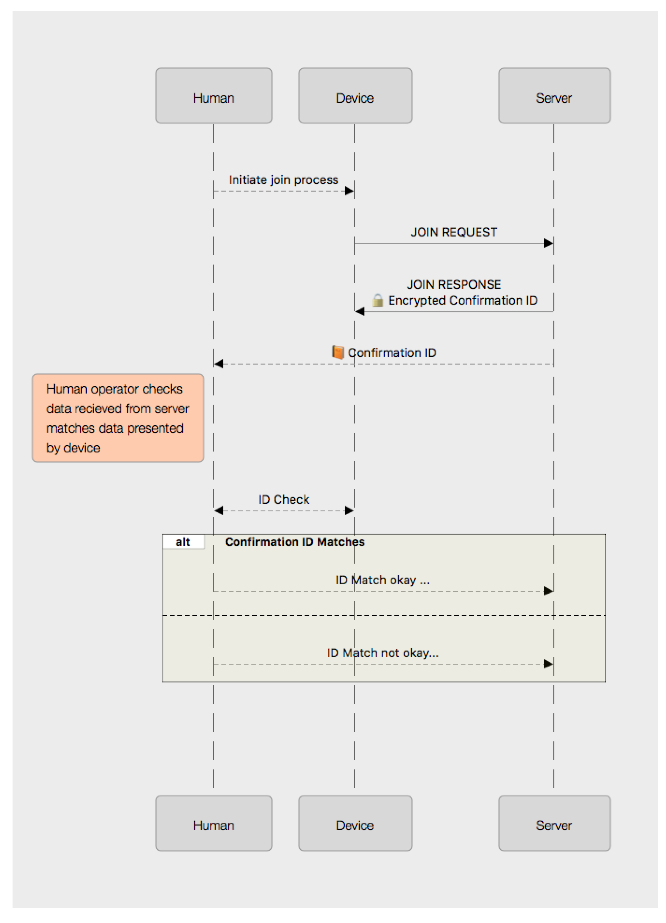
The first of these is a system with a human operator in the loop. This approach might be taken when a trusted human operator is present with the device at the time of the join operation (as might be the case for a sensor or other device being manually deployed).
In this class of system, the join operation is expected to be conducted with relation to a specific (pre-known) device being deployed or installed. The device initiates the process by sending a SRUP_MESSAGE_TYPE_HM_JOIN_REQ message.
In response to this, the server would send a SRUP_MESSAGE_TYPE_HM_JOIN_RESP message, which would contain an encrypted value (a suitable randomly-selected 128-bit nonce value, encrypted using the device’s public key). On receiving this message, the device would present the decrypted version of that data for observation by a human observer. In this way, the trusted human observer, in communication with the operator of the server (outside of the protocol) or who is operating the server themselves, would be able to compare the identity presented to the server and the identity presented by the device being observed and deployed. This enables the operator of the server to be assured that the physical device that was observed was the device that has the identity associated with the join request. Depending on the device (and the nature of the system, as well as technical proficiency of the operator), this presentation could be done in a number of different ways. In a simple case, the device could display the decrypted value on a suitable display on the device.
A sequence diagram showing the information flow during a human-moderated join operation is shown in Figure 1.
Other techniques for presenting a UUID in a human-readable form are explored in Section 8.
5.2.2. Autonomous System
The second use-case is one where the device requesting the join is an autonomous entity and so is operating without direct human intervention. In a system of this type, the join request could, for example, be made as a part of the process for an autonomous device entering a specific region of control.
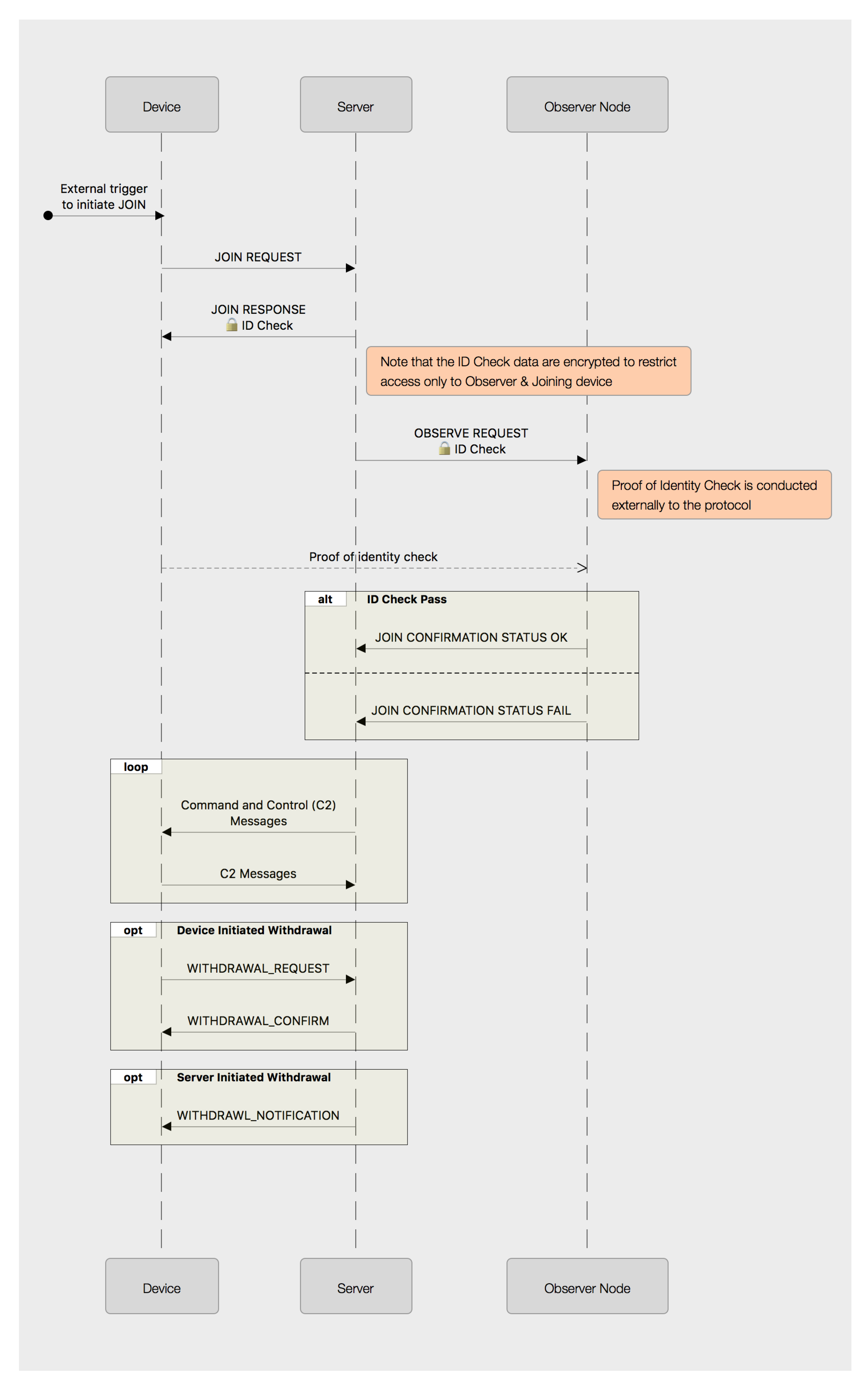
The general pattern of operation in this more complex example would be for the server to generate encrypted data in the same manner as before, but then request that another (already connected and trusted) device make the observation check via a point-to-point connection outside of the protocol. For example, if the autonomous platform making the join request recognises that it has entered into the region subject to C2 by the server by virtue of establishing a point-to-point connection with some kind of beacon device, it could use the identity of this beacon as a part of its join request. The server could then send the beacon a message containing the value that it should expect to receive from the device. Once the joining device has received the server’s request for confirmation, it would then transmit the confirmation data via the point-to-point link to the beacon, which would be responsible for checking that the two values matched and signalling back to the server.
Under SRUP, this would be accomplished by having the device send an SRUP_MESSAGE_TYPE_OBS_JOIN_REQ message containing its own identity and the identity of the observing node and signed with the requesting device’s key.
The server would then generate a 128-bit UUID value and an SRUP_MESSAGE_TYPE_OBSERVE_REQ message to the observing node, which would contain an encrypted version of the value (encrypted with the observing node’s public key) and a signature.
The server would also send a SRUP_MESSAGE_TYPE_OBS_JOIN_RESP message back to the joining device, using the same scheme, consisting of an encrypted version of the confirmation value, this time using the joining node’s public key. The joining node would then be required to prove its identity to the observing node outside of SRUP (for example, via a short-range point-to-point link); and then, finally, the observing node would send a regular SRUP response message to the server, with a status value to signal whether the proof of Identity has been successful or not.
Figure 2 shows a sequence diagram depicting the protocol message flows for an externally-observed join; together with both a device-initiated and a server-initiated withdrawal operation.
6. Key Revocation
Key revocation is a vital, but often overlooked [26] aspect of any IoT system. It is however simple to implement in the context of a C2 server-based approach to an IoT system. There are two types of revocation that need to be considered.
- The removal of a device as a subordinate to a C2 server such that it is no-longer subject to control by that server, whilst retaining the device within the wider system (this is the opposite of a join operation);
- The permanent withdrawal of the device from the system as a whole (the opposite of initial device registration).
To remove a device from a particular C2 network within SRUP, the device may elect to resign (by sending a SRUP_MESSAGE_TYPE_RESIGN_REQ message), or it may be terminated by the server (using a SRUP_MESSAGE_TYPE_TERMINATE_COM message).
If the device is being disconnected by the server, the server would simply remove the record pertaining to the device from its list of devices. If the device is requesting to resign, then the server should send a response message with a status to indicate whether or not that resignation is accepted; and (if it is) the key would be removed as before.
For a permanent (system-wide) de-registration of a device, SRUP could also be used (despite the fact that the initial registration took place outside of the protocol). The data exchange is essentially the same as for the resign/terminate use-case, but with message types of SRUP_MESSAGE_TYPE_DEREGISTER_REG, or SRUP_MESSAGE_TYPE_DEREGISTER_COM; the result of which would be the device’s key being permanently removed from the system’s key store.
7. Potential Attack Mechanisms
In the event that an attacker is able to gain physical access to the device, it can be assumed that, unless the device has been built to utilize encrypted storage and a trusted boot process [27], the attacker would gain access to any data stored on the device. In the context of a SRUP device, most significantly, this equates to the server’s public key and the device’s private key. Since the server’s public key is by definition publicly available (on demand via the registration process, if nowhere else), we may largely disregard this as being of use to an attacker. Having access to the device’s private key, however, means by the definition used in Section 4.2 that the attacker may take the identity of the device. As such, any messages that the system would permit the device to send could be spoofed and be sent by any other device that the attacker may devise (and assign the original device’s identity to).
Although a system based on SRUP makes no attempt to provide a mechanism to monitor or detect such identity theft, the centralized nature of the C2 server paradigm (with no peer-to-peer messaging) means that the potential damage that can be caused by that identity theft may be contained to the server. Other devices on the SRUP network cannot be directly affected. Given that by definition devices are always subordinate to the server, there is limited scope for damaging the system via spoofing device messages, beyond that which may be caused by directly interfering with the device’s sensors. In the event that such an attack were detected, the device can be de-registered to revoke its ability to communicate on the system.
Although such a device may be able to re-register and gain a new identity; in a human-moderated system, it would not be able to join the server without the assistance of a compromised (but trusted by the system) human (a situation that almost no security paradigm would be able to protect against). Even in an automated or unmoderated system, being able to join (or retain) membership of a control group is, as previously discussed, of very limited value to an attacker.
The greatest threat to any centralized C2 system is the compromise of the centre; however, the asymmetric cryptographic approach adopted by SRUP means that compromise of a subordinate node has no impact on the security of the central server.
The greatest threat to the system is if an attacker were to compromise a beacon node; as in this eventuality, the attacker would be able to spoof any observation check conducted using that beacon. Although protection against physical tampering is beyond the scope of SRUP, it should be noted that protecting an observer node from physical compromise is critical to the overall security of any system utilizing such devices.
8. Methods for Easy Human Comparison of UUID Values
For a system reliant on a human comparison, there are a number of ways that a 128-bit number could be presented. Conventionally, such numbers are shown as a string representation of a 32-digit hexadecimal value. Where such values are generated as true UUIDs, they are typically presented using the 8-4-4-4-12 format described in [28]. Given the visual clarity of this format, it is desirable to adopt the same approach to presenting the 16 bytes of any 128-bit value. An example of a 128-bit UUID used by the protocol formatted in this manner can be seen in Figure 3.
Such an option is the simplest method to implement: a small character, text-mode Liquid Crystal Display (LCD) suitable for displaying such a value (without hyphenation) would likely add only around $3–4 to the bill-of-materials cost for a device; and such an approach would be technically compatible with even the most basic microcontroller.
Requiring the careful comparison of two 32-character hexadecimal values is, however, not an especially user-friendly interface and is really only well suited to environments with specialist users. Instead, other options could be adopted to present the value for comparison. Crucially, it is not important that the observer be able to identify the underlying value presented to them; but rather only to recognise whether two examples presented match or differ from each other.
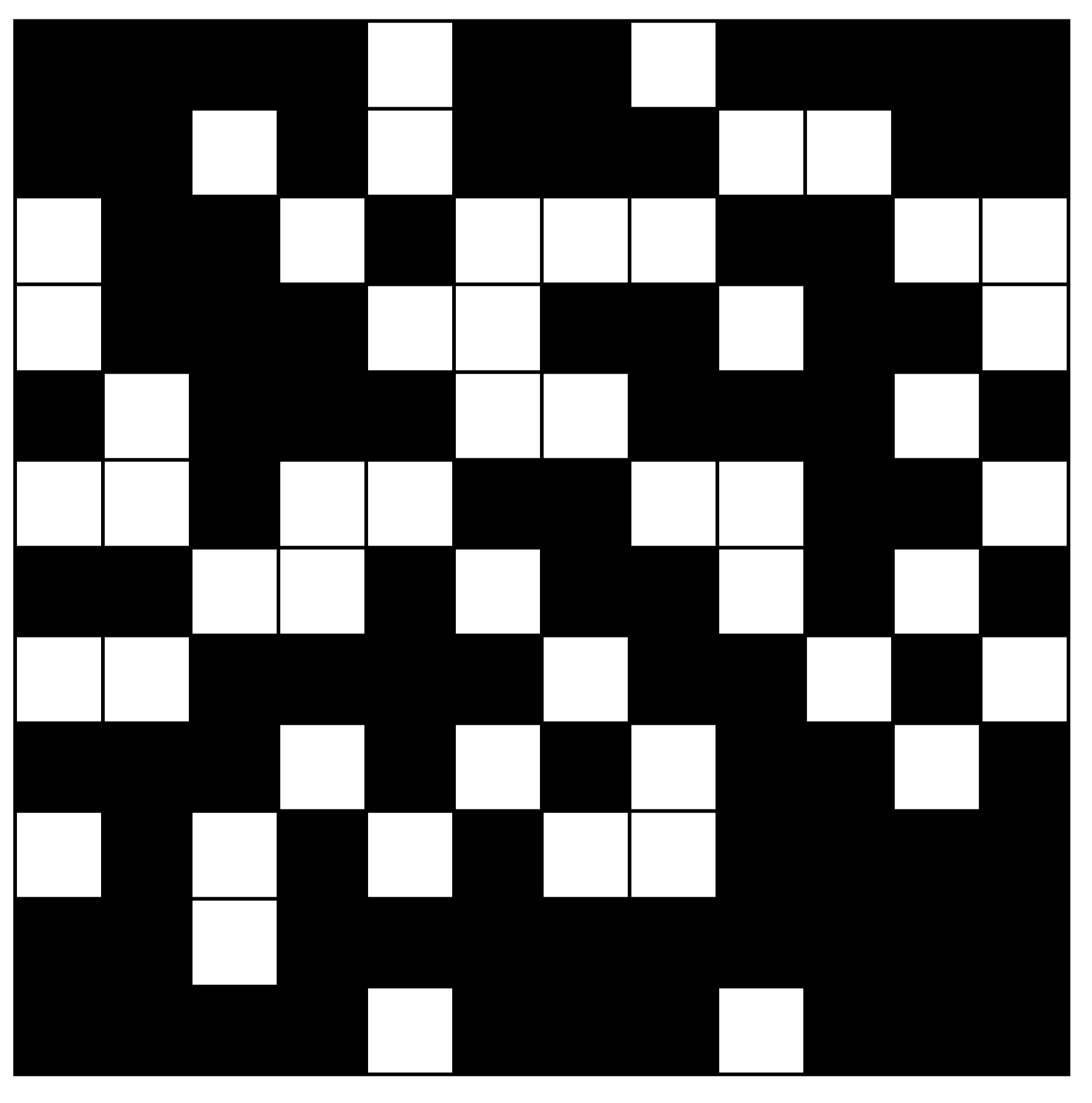
8.1. Pictographic Representation
One way to do this might be to present the 128-bit value in the form of a human-readable pictograph consisting of a grid of 144 monochromatic cells. Since this gives us 16 cells too many for a 128-bit value, we would need to use 16 additional ‘bits’ of fixed padding; for example, by placing a 2 × 2 block in each corner. Such a pictograph would have an appearance something similar to that of a 2D barcode: although one that is designed for human recognition, rather than machine readability. Whilst a specific scheme for encoding such a UUID into a monochrome pictograph has not been proposed, an example of the appearance of such a pictograph is shown in Figure 4 to contrast with the other representational approaches discussed.
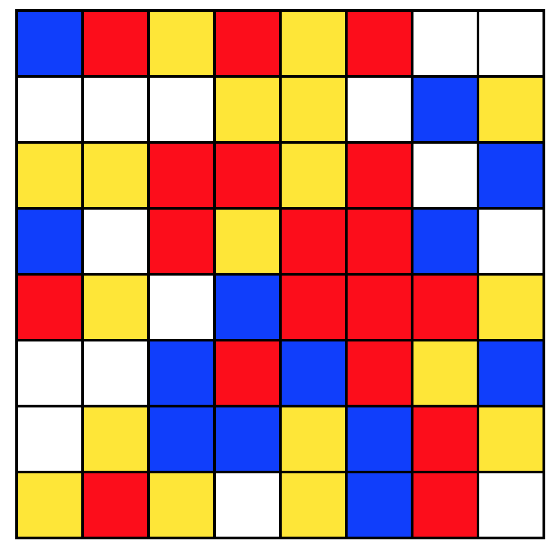
The value could also be presented in the form of a smaller grid of cells, coloured with one of four colours. With careful selection of the colours, it is possible to produce a grid with a sufficient visual difference to be easily distinguished; and avoiding combinations that were indistinct for those with various forms of colour-blindness. Again, whilst a specific protocol for such encoding has not been devised as a part of this work, an example of one such method (where the content of each square in the pictograph is determined by the value of two-bits in the UUID) is shown in Figure 5, for comparison with the other approaches described.
For a device with a graphical screen capable of rendering such a pictograph (or which has the necessary hardware to permit its connection to an external display for the purposes of validating the join operation), an image of one of these two types could be displayed by the device and also presented in the user-interface to the server (e.g., a web page) after the registration process had been initiated.
For devices without a suitable screen, the device could utilize a BLE connection to a smart-phone or tablet running simple application software, which could be used to display the verification code pictogram. Although this is potentially less secure as it increases the attack surface, by adding an additional communications channel that could be targeted by an attacker, the short-range nature of BLE and the time sensitivity of the join operation process mean that in practice, this would be fairly low risk in a real-world application of such a system.
8.2. Word-List Representation
An alternative to a graphical depiction of the value would be to present the value in the form of a “phrase” generated from words taken from a standard word-list; with the multiple parts of the 128-bit value mapped onto individual words from the list.
Such approaches have been shown before (for example, [29]) for presenting cryptographic keys to users, but can easily also be applied to the presentation of identity.
For example, we can divide a 128-bit value into ten, 12-bit fragments: with each 12-bit fragment being mapped on to one of a list of different English-language words, drawn from a suitably distinctive word-list. A suitable world-list would be one designed for use as a means of providing users a mechanism to generate high entropy passwords [30]. The remaining eight bits of the original 128-bit value could then be represented either by one of 256 additional words; or by using words from within the same list (and using the previously described technique of padding the value with four additional ‘fixed’ bits). Thus, the user would be presented with a “phrase” for comparison to assure identity during the join operation.
An example of using words selected from such a word-list to generate an identity-phrase can be seen in Figure 6.
The options for presentation of this phrase to the user are similar to those for the presentation of both pictographs and the text strings, although clearly, a screen suitable to display simple textual information is very-much simpler than that which might be required to render a coloured pictograph.
9. Results and Future Work
9.1. Results
An initial protocol test-bed was constructed, and an example showing the use of an update message was demonstrated at the 2016 3rd IEEE World Forum on the Internet of Things. This implementation consisted of an IoT C2 system: using the Mosquitto broker; a Raspberry Pi 3 as an example device, alongside an example device-side daemon; and a C2 server. Both the daemon and server were implemented using the SRUP library, C++ components and Python scripts, with the interprocess communication handled using Apache Thrift [31]. Although not formally measured, the performance of this system was more than adequate. A short video demonstrating the update messages and the C2 interface was produced. [32]
A packet capture showed that the most complex message-type measured (an update initiate message) consisted of 424 bytes of SRUP data (consisting of a 33-byte URL, a 64-byte SHA-256 digest and an 8-byte target; plus the message signature, transaction token and other protocol overheads), sent as 493 bytes of MQTT traffic. Even this message type (the most complex, consisting of more fields than any other message type) could easily be delivered over even an unreliable or slow Internet connection. The adoption of MQTT QoS 1 (to provide guaranteed delivery of the message) adds an additional MQTT PUBACK message (consisting of just 60 bytes total, when using Internet Protocol Version 4 (IPv4)).
The cryptographic functions used to support the SRUP protocol are also highly efficient in terms of performance, even on relatively low-power hardware. The implementation tested thus far, on a Raspberry Pi 3 and using OpenSSL to provide both the SHA-256 digests and the RSA signatures, was more than adequately executed. In a test case, signing and verifying a representative SRUP initiate message, using a Raspberry Pi 3 and averaged over five runs, signing took an average of 56.68 ms, and verifying the signature took just 9.91 ms.
Work continues to provide a complete reference implementation of the SRUP protocol, as described in this paper, in the form of a C++ library.
9.2. Planned Future Work
Once the implementation of all features of the SRUP protocol is complete, a series of experiments is planned to provide an objective measurement of the protocol in action, measuring both the performance and scalability of the protocol as representative of real-world C2 applications.
10. Conclusions
In this paper, we have shown how the SRUP protocol can be extended through the introduction of additional message-types, to be used as a general-purpose protocol for authenticated IoT communications. We have also proposed some methods that could be utilized to provide a means for physical devices to prove they have an identity corresponding to a logical device within the network, using either human- or a machine-in-the loop methods.
Full details of all the message types within the SRUP protocol may be found in the protocol specification document [33].
The source code for the latest version of the library and an example implementation of the device-side daemon, as well as C2 server are all released under the terms of the MIT open licence. The latest version can be found at: https://github.com/dstl/SRUP/.
Acknowledgments
This work has been funded by the United Kingdom Defence Science and Technology Laboratory (Dstl). Dstl is a part of the U.K. Ministry of Defence.
Author Contributions
A.J. Poulter, Steven Johnson, and Simon Cox conceived and designed the experiments and research; A.J. Poulter performed the experiments and wrote the source code; A.J. Poulter, Steven Johnson, and Simon Cox discussed, wrote and edited the paper.
Conflicts of Interest
The authors declare no conflict of interest.
References
- Poulter, A.J.; Johnston, S.J.; Cox, S.J. SRUP: The secure remote update protocol. Proeceedings of the 2016 IEEE 3rd World Forum on Internet of Things (WF-IoT), Reston, VA, USA, 12–14 December 2016; pp. 42–47. [Google Scholar]
- Kolias, C.; Kambourakis, G.; Stavrou, A.; Voas, J. DDoS in the IoT: Mirai and Other Botnets. Computer 2017, 50, 80–84. [Google Scholar] [CrossRef]
- Bertino, E.; Islam, N. Botnets and Internet of Things Security. Computer 2017, 50, 76–79. [Google Scholar] [CrossRef]
- Banks, A.; Gupta, R. (Eds.) MQTT Version 3.1.1; Technical Report; Organization for the Advancement of Structured Information Standards (OASIS): Burlington, MA, USA, 2014. [Google Scholar]
- Postel, J. Transmission Control Protocol; Technical Report RFC793; Internet Engineering Task Force: Fremont, CA, USA, 1981. [Google Scholar]
- Dierks, T.; Rescorla, E. The Transport Layer Security (TLS) Protocol Version 1.2; Technical Report RFC5246; Internet Engineering Task Force: Fremont, CA, USA, 2008. [Google Scholar]
- Eclipse. Mosquitto—An Open Source MQTT v3.1/v3.1.1 Broker. Available online: http://mosquitto.org (accessed on 8 November 2015).
- Franks, J.; Leach, P.J.; Luotonen, A.; Hallam-Baker, P.M.; Lawrence, S.D.; Hostetler, J.L.; Stewart, L.C. HTTP Authentication: Basic and Digest Access Authentication; Technical Report RFC2617; Internet Engineering Task Force: Fremont, CA, USA, 1999. [Google Scholar]
- Reschke, J. The ’Basic’ HTTP Authentication Scheme; Technical Report RFC7617; Internet Engineering Task Force: Fremont, CA, USA, 2015. [Google Scholar]
- Steiner, J.G.; Neuman, C.; Schiller, J.I. Kerberos: An Authentication Service for Open Network Systems. In Proceedings of the Usenix Winter Confernce, Dallas, TX, USA, 9–12 February 1988; pp. 191–202. [Google Scholar]
- Boost. Boost UUID. 2010. Available online: http://www.boost.org/doc/libs/1640/libs/uuid/uuid.html (accessed on 30 June 2017).
- Sornin, N.; Luis, M.; Elirich, T.; Kramp, T.; Hersent, O. LoRaWAN™ Specification; LoRa Alliance: Beaverton, OR, USA, 2015. [Google Scholar]
- Cooper, D.; Santesson, S.; Farrell, S.; Boeyen, S.; Polk, W.; Housley, R. Internet X. 509 Public Key Infrastructure Certificate and Certificate Revocation List (CRL) Profile; Technical Report RFC5280; Internet Engineering Task Force: Fremont, CA, USA, 2008. [Google Scholar]
- Espressif Systems (Shanghai) Pte. ESP32 Overview. 2017. Available online: https://www.espressif.com/en/products/hardware/esp32/overview (accessed on 30 June 2017).
- Ellis, J.H. The Possibility of Secure “Non-Secret” Digital Encryption; Technical Report 3006; GCHQ: Cheltenham, UK, 1970.
- Cocks, C.C. A Note on ‘Non-Secret Encryption’; Technical Report; GCHQ: Cheltenham, UK, 1973.
- Rivest, R.L.; Shamir, A.; Adleman, L.M. A Method for Obtaining Digital Signatures and Public-Key Cryptosystems. Commun. ACM 1978, 21, 120–126. [Google Scholar] [CrossRef]
- Boneh, D. Twenty Years of Attacks on the RSA Cryptosystem. Not. Am. Math. Soc. 1999, 46, 203–213. [Google Scholar]
- United States Computer Emergency Readiness Team (US-CERT). SSL 3.0 Protocol Vulnerability and POODLE Attack. Technical Report Alert (TA14-290A); 2014. Available online: https://www.us-cert.gov/ncas/alerts/TA14-290A (accessed on 23 February 2017).
- Schäling, B. The Boost C++ Libraries; XML Press: Fort Collins, CO, USA, 2011. [Google Scholar]
- Fielding, R.T.; Taylor, R.N. Principled design of the modern Web architecture. ACM Trans. Internet Technol. 2002, 2, 115–150. [Google Scholar] [CrossRef]
- International Standards Organization. Information Technology—Automatic Identification and Data Capture Techniques—Bar Code Symbology—QR Code; Technical Report ISO/IEC 18004; International Standards Organization: Geneva, Switzerland, 2000. [Google Scholar]
- ECMA International. Near Field Communication—Interface and Protocol (NFCIP-1); Technical Report ECMA-340 (ISO/IEC 18092:2013); ECMA International: Geneva, Switzerland, 2013. [Google Scholar]
- Bluetooth Special Interest Group. Specification of the Bluetooth System; Bluetooth Special Interest Group: Kirkland, WA, USA, 2014. [Google Scholar]
- Google. Eddystone Protocol Specification; Google: Mountain View, CA, USA, 2016. [Google Scholar]
- Henderson, C. IoT: End of Shorter Days. Presentation to RSA Conference 2017, San Francisco, CA, USA, 2017; Available online: https://www.rsaconference.com/videos/iot-end-of-shorter-days (accessed on 22 February 2017).
- Johnston, S.J.; Scott, M.; Cox, S.J. Recommendations for securing Internet of Things devices using commodity hardware. In Proceedings of the 2016 IEEE 3rd World Forum on Internet of Things (WF-IoT), Reston, VA, USA, 12–14 December 2016; pp. 307–310. [Google Scholar]
- Leach, P.; Mealling, M.; Salz, R. A Universally Unique IDentifier (UUID) URN Namespace; Technical Report RFC4122; Internet Engineering Task Force: Fremont, CA, USA, 2005. [Google Scholar]
- McDonald, D.L. A Convention for Human-Readable 128-bit Keys; Technical Report RFC 1751; Internet Engineering Task Force: Fremont, CA, USA, 1994. [Google Scholar]
- Bonneau, J. Deep Dive: EFF’s New Wordlists for Random Passphrases; Electronic Fronteer Foundation: San Francisco, CA, USA, 2016; Available online: https://www.eff.org/deeplinks/2016/07/new-wordlists-random-passphrases (accessed on 31 March 2017).
- Slee, M.; Argawal, A.; Kwiatkowski, M. Thrift: Scalable Cross-Language Services Implementation; Technical Report; Facebook: Palo Alto, CA, USA, April 2007. [Google Scholar]
- Poulter, A.J. The Secure Remote Update Protocol (SRUP). 2016. Available online: https://youtu.be/aKTODVEpI1w (accessed on 28 September 2017).
- Poulter, A.J. The Secure Remote Update Protocol: A Specification University of Southampton. 2017. [Google Scholar] [CrossRef]
Figure 1.
The sequence of a human-in-the-loop join operation.

Figure 2.
A sequence diagram showing the message flows for autonomous join and withdrawal operations. C2: command and control.
Figure 2.
A sequence diagram showing the message flows for autonomous join and withdrawal operations. C2: command and control.

Figure 3.
An example of a 36-character string depicting a 128-bit binary value in standard hexadecimal notation.
Figure 3.
An example of a 36-character string depicting a 128-bit binary value in standard hexadecimal notation.

Figure 4.
An example black and white, 12 × 12 grid depicting a 128-bit binary value; in which the colour of each cell corresponds to the value of individual bits within the value.
Figure 4.
An example black and white, 12 × 12 grid depicting a 128-bit binary value; in which the colour of each cell corresponds to the value of individual bits within the value.

Figure 5.
An example four-colour, 8 × 8 grid depicting a 128-bit binary value; in which the colour of each cell corresponds to the the value of two-bits in the value.
Figure 5.
An example four-colour, 8 × 8 grid depicting a 128-bit binary value; in which the colour of each cell corresponds to the the value of two-bits in the value.

Figure 6.
An example of an identity phrase generated using a word-list.

© 2017 by the authors. Licensee MDPI, Basel, Switzerland. This article is an open access article distributed under the terms and conditions of the Creative Commons Attribution (CC BY) license (http://creativecommons.org/licenses/by/4.0/).
Share and Cite
MDPI and ACS Style
Poulter, A.J.; Johnson, S.J.; Cox, S.J. Extensions and Enhancements to “the Secure Remote Update Protocol”. Future Internet 2017, 9, 59. https://doi.org/10.3390/fi9040059
AMA Style
Poulter AJ, Johnson SJ, Cox SJ. Extensions and Enhancements to “the Secure Remote Update Protocol”. Future Internet. 2017; 9(4):59. https://doi.org/10.3390/fi9040059
Chicago/Turabian StylePoulter, Andrew John, Steven J. Johnson, and Simon J. Cox. 2017. "Extensions and Enhancements to “the Secure Remote Update Protocol”" Future Internet 9, no. 4: 59. https://doi.org/10.3390/fi9040059
Note that from the first issue of 2016, this journal uses article numbers instead of page numbers. See further details here.