
Static Eccentricity Fault Analysis of Surface-Mounted Permanent Magnet Electromotor with Skewed Slots Based on 2D FEA

Henan Key Laboratory of Optoelectronic Sensing Integrated Application, College of Electronic and Electrical Engineering, Henan Normal University, Xinxiang 453007, China
World Electr. Veh. J. 2021, 12(4), 176; https://doi.org/10.3390/wevj12040176
Submission received: 31 August 2021
/
Revised: 28 September 2021
/
Accepted: 30 September 2021
/
Published: 2 October 2021
(This article belongs to the Special Issue Towards Intelligent E-Mobility—Selected Papers from The 34th International Electric Vehicles Symposium and Exhibition (Nanjing, China))
Abstract
:It is of significance to analyze the performance of eccentric electromotor for the research on the electric vehicle wheel drive system’s operational reliabilities. We developed a fast equivalent algorithm in which the two-dimensional finite element calculation results are translated into three-dimensional calculation results. An electromotor with skewed slot was decomposed into straight-slot electromotor units that were series-wound. A prototype electromotor driven by square wave current under healthy and eccentric conditions was calculated, and the computation accuracy of the equivalent algorithm was analyzed. The air-gap magnetic field and induced electromotive force were calculated and contrasted. The study results indicate that the magnetic field distribution and the induced electromotive forces of winding elements with different axis positions were affected transparently by grievous eccentricity, yet the induced electromotive force of one phase winding and average value of torque remained virtually invariable. The reference to reliability analysis of electric vehicle wheel drive system is provided.
1. Introduction
Due to high efficiency, high power density, and good reliability, permanent magnet electromotor is widely used as the core component of the propulsion system in low-power electric vehicles [1,2,3,4]. Assembly technology and machining accuracy in the manufacturing process are imperfect, and the electromotor may have slight air-gap eccentricity before leaving the factory [5]. When the electromotor runs for a long time under severe and complicated working conditions, the wear of bearings will also lead to eccentric air gap. The influence of air-gap eccentricity on electromotor is obviously negative, and therefore it is necessary to study these adverse effects in advance.
Eccentricity of electromotor will not only change the internal magnetic field distribution but will also affect the dynamic performance, especially the tangential electromagnetic torque ripple and radial unbalanced magnetic pull, which will lead to the deterioration of noise, vibration, and smoothness [6,7,8]. Many researchers have conducted in-depth and detailed research on eccentric electromotor. M. Ojaghi proposed a two-dimensional modified winding function theory for squirrel-cage asynchronous electromotor to obtain the analytical expressions, which was suitable for axial uniform or non-uniform eccentricity and healthy situations [9]. J. J. Rocha Echeverria developed a new calculation tool to calculate the magnetic attraction in the no-load air-gap with the misaligned centers of stator and rotor, regardless of whether the eccentricity was dynamic or static [10]. H. Lee proposed an analytical method to calculate the characteristics of eccentric electromotor quickly according to the design variables [11]. H. Kim established an analytical model of the force by Maxwell stress method and studied the influence of unbalanced magnetic tension on the vibration of permanent magnet synchronous electromotor caused by air-gap eccentricity [12]. H. Lasjerdi proposed a comprehensive method based on the winding function method, and a non-invasive index was used to identify the type or even percentage of mechanical eccentricity failures [13]. A. Aggarwal used incremental inductance method to detect static eccentricity in off-line state [14]. J. Shin proposed a reliable method for classification of rotor cage and detection of eccentricity faults [15]. According to the difference of research contents, the literatures in the field of air-gap eccentricity can be broadly divided into two types: (a) by detecting the characteristic signals such as voltage and current, the location and type of eccentricities can be diagnosed accurately and non-destructively; (b) using finite element method or analytical method, the operating characteristics of electromotor under different eccentric conditions are predicted. The research content of this paper belongs to the latter.
Skewed slot or skewed pole is the effective method to suppress torque ripple, which is widely used in the design of various electromotors [16,17,18,19]. There are many studies on air-gap eccentricity of straight slot electromotor, but studies on air-gap eccentricity of skewed electromotor are rare. In this paper, a fast equivalent algorithm for synthesizing three-dimensional results from a two-dimensional field analysis data series was developed to calculate the characteristics of the electromotor with skewed stator slot and eccentric rotor driven by square wave current. The calculation accuracy of the algorithm was deduced and studied. Compared with the experimental data of prototypes, the effectiveness of the algorithm is verified.
2. Geometric Structure of Air-Gap Eccentricity
Any actual situation of air-gap eccentricity is a different combination of static and dynamic eccentricity [20,21,22]. A schematic diagram of air-gap eccentricity is shown in Figure 1. In order to highlight the visual effect, we artificially exaggerated the air-gap thickness and the degree of eccentricity compared with the real data of prototype.
Under healthy conditions, the geometric centers of stator and rotor coincide, and the rotor rotates around its own center. However, after the air-gap eccentricity occurs, the two centers no longer coincide. If dynamic eccentricity occurs, the rotor rotates around the center of the stator. If static eccentricity occurs, the rotor rotates around its own center [23,24]. Only the static eccentricity is studied in this paper, and the air-gap length g can be expressed as
where Rin is the inner radius of stator, e is the eccentric distance, θ is the rotor position angle, α is the eccentric angle of rotor, and rout is the outer radius of rotor.
It can be seen from Equation (1) that once the static eccentricity occurs, the air-gap length along the circumferential direction is no longer equal everywhere. In the magnetic flux path, the permeability of air is much smaller than that of the soft magnetic material constituting the iron core. Compared with the magnetic circuit of a healthy electromotor, the longer the air-gap length, the smaller the magnetic density in the air gap, and vice versa. The degree of eccentricity λ can be defined as
where g0 is the uniform air-gap length of a healthy electromotor.
3. Equivalent Algorithm
3.1. Principle
Magnetic circuit method is usually adopted to predict the performance of skewed electromotor in traditional design process. However, the calculation accuracy of magnetic circuit method is relatively low. In order to obtain higher calculation accuracy, finite element method is often adopted at present. Two-dimensional finite element method has advantages of simple modelling and less calculation, but it is only suitable for analyzing straight slot electromotor with identical cross sections along the axial direction. Three-dimensional geometric structure of skewed electromotor leads to different axial cross sections, and thus two-dimensional finite element method cannot be adopted directly. Compared with two-dimensional finite element model, three-dimensional finite element model is more difficult to model, and the large number of three-dimensional subdivision elements leads to a huge amount of computation.
In practical engineering, it is frequently necessary to calculate abundant prototype schemes within a short time, while the establishment and calculation of three-dimensional finite element models are quite time-consuming. In order to provide consideration to the efficiency and accuracy of calculation, we adopted a fast equivalent algorithm. The algorithm is based on two-dimensional finite element method, which is not only accurate, but also easy to model, with less computation. As shown in Figure 2, the ideology is to divide a skewed electromotor into several sections along the axial direction and treat each section as an independent unit [25,26,27,28].
In the figure, the thick blue line represents the original whole conductor in the skewed slot, and the thick red line segments represent the equivalent straight conductor. The more segments, the smaller the skew angle of each segment. Then, each unit can be approximately regarded as a straight slot electromotor and is calculated by two-dimensional finite element method. According to the designed superposition rules, the performance of the whole skewed electromotor can be obtained by numerically processing the data sequence obtained by two-dimensional finite element calculation. The equivalent calculation model can meet the accuracy requirements of general engineering, and the overall modeling difficulty and solution time are better than those of the three-dimensional finite element model.
Under the condition of ignoring the leakage magnetic field at the end of the electromotor, the mathematical description of solving the straight slot electromotor by two-dimensional transient field method can be expressed as follows
where v is the velocity of winding, Az is the magnetic potential of vector, Jz is the density of current, E is the induced electromotive force of winding, and is the flux linkage of winding.
In the equivalent model, the mathematical description of solving the series straight slot electromotor segments can be expressed as
where n is the number of segments, Azi is the magnetic potential of the vector of the ith segment, Ei is the induced electromotive force of the ith segment, and is the flux linkage of the ith segment.
3.2. Calculation Accuracy
As shown in Figure 3, a charged and moving inclined conductor is in the kth harmonic magnetic field of the electromotor. In the figure, Bmk is the amplitude of harmonic magnetic field, αk is the position of one end of the conductor in harmonic magnetic field, βk is the skew angle in harmonic magnetic field, L is the projection length of the conductor along the axial direction of electromotor, and I is the current passing through the conductor.
The electromagnetic force Fk and induced electromotive force Ek of the conductor in harmonic magnetic field can be expressed as
Taking the fundamental magnetic field as an example, the equivalent model can adopt two segmentation modes, as shown in Figure 4. In segmentation mode 1, the end point of each conductor segment is selected as the section position, and therefore the minimum segment number is two. In segmentation mode 2, a certain middle position of each conductor segment is selected as the section position, and therefore the minimum segment number is one. In the figure, the inclined thick line indicates the original conductor in the skewed slot, which is divided into n segments with equal length. The length of each segment along the axial direction of the electromotor is L/n, and the skew angle of each segment is β/n. The tiny circle indicates the section position, and χ is the distance between the section position and an end point of each section.
The skew angle of the ith segment with two segmentation modes can be expressed as
In the kth harmonic magnetic field, the electromagnetic force and induced electromotive force with two segmentation modes calculated by the equivalent model can be expressed as
It can be seen from Equations (8) and (9) that the mathematical expressions of electromagnetic force and induced electromotive force are highly similar. Then, the mathematical expressions of the relative errors of electromagnetic force and induced electromotive force are completely consistent. Therefore, the relative errors of electromagnetic force and induced electromotive force with two segmentation modes can be uniformly expressed as
By comparing the calculation results of Equations (10) and (11) under the condition that the variables in the error expressions take the same values, we see that the convergence performance of mode 2 is obviously better than that of mode 1. Therefore, only mode 2 is adopted in this paper.
4. Calculation and Analysis of Prototype
4.1. Selection of Segment Number
There is no doubt that increasing the segment number can improve the calculation accuracy of the equivalent model. However, too many segments may be unnecessary, and they may increase the calculation amount obviously, resulting in too long a calculation time. In order to select the segment number rationally, we must discuss the factors affecting the calculation accuracy before establishing the equivalent model of prototype. The skew angle of prototype in this paper is a slot-pitch angle, which is a mechanical angle of 15 degrees. When the segment number increases from 5 to 20 and the harmonic order increases from 1 to 20, the relative errors with different combinations of segment number and harmonic order are given, as shown in Figure 5.
Comparing and studying the change trend and specific value of relative error data series can provide reliable references for selecting the number of segments reasonably. In order to calculate the electromagnetic force and induced electromotive force in higher harmonic magnetic field accurately, more segments have to be taken; otherwise, the equivalent accuracy is quite low. For example, if the number of segments is only 5, the calculation error in the 20th harmonic magnetic field is close to 150%, which is unacceptable equivalent calculation accuracy. In any harmonic magnetic field, increasing the number of segments can undoubtedly improve the calculation accuracy. However, a large number of segments means that the amount of calculation is multiplied, and the equivalent calculation model itself loses its meaning. Moreover, from the data sequence of errors, it can be seen that once the number of segments is higher than a certain value, increasing continuously has little effect on improving accuracy. For example, if the number of segments is 15, the errors in the 1st to 20th harmonic magnetic fields are less than 10%, and it is of little significance to continuously increase the number of segments to improve the calculation accuracy.
The key to choose the number of segments reasonably lies in the proportion of harmonic components in the magnetic field in the real prototype. If the proportion of higher harmonic components is large, then a great number of segments are needed. On the contrary, if the proportion of low-order harmonic components accounts for the vast majority, then the existence of high-order harmonic components can be ignored and only a small number of segments can be taken.
Therefore, before reasonably determining the number of segments, it is necessary to use the two-dimensional finite element method to analyze the amplitude and proportion of each harmonic magnetic field in the prototype.
4.2. Two-Dimensional Finite Element Model of Prototype
Radial cross sections of prototype drawn according to the initial design scheme are shown in Figure 6. In the figure, A, B, and C indicate electromotor winding regions; + and − indicate reference positive direction of current; and N and S indicate the permanent magnet regions.
There are 24 slots in the stator. Each phase of stator winding consists of four winding elements connected in series, that is, eight stator slots. Considering that the structures of the three-phase windings are the same, this paper only analyzed the A-phase as an example. Winding element Aj (j = 1,2,3,4) is composed of regions Aj+ and Aj−. The A-phase winding is composed of winding elements Aj connected in series. Twenty-four stator slot regions can be divided into four groups, namely, groups I, II, III, and IV.
There are four pairs of permanent magnets in the rotor. Every two adjacent magnets form a pair. These eight permanent magnets can be divided into four pairs, namely, pairs I, II, III, and IV.
4.3. Calculation and Analysis
In a healthy state, the air-gap thickness should be equal everywhere along the circumferential direction. The design thickness of prototype is only 0.5 mm. However, once static eccentricity occurs, the geometric center of the rotor will deviate from the geometric center of the stator by a certain distance. Then, the thickness of the air gap is no longer equal everywhere.
The stator remains stationary. The rotor is moved to the right horizontally by 0.2 mm. Taking the geometric center of new rotor as the rotation axis, we can artificially manufacture a static eccentricity.
The degree of eccentricity λ reaches 40%. The air-gap thickness at 0 degree circumferential position is the smallest at only 0.3 mm. The air-gap thickness at 180 degree circumferential position is the largest at 0.7 mm. Compared with the healthy state, the air-gap thickness at 90 degrees or 270 degrees has little change.
The distribution of magnetic flux density is shown in Figure 7. It can be seen from the figure that after the occurrence of static eccentricity, some changes took place in the magnetic density distribution in each region.
Taking the geometric center of the eccentric rotor as the center, we established a circular closed path in the middle of air gap as sampling position. The data sequence of normal component of magnetic flux density is shown in Figure 8. In the figure, different values of eccentric distance are compared. Eccentric distance equal to zero indicates that the electromotor is healthy. Where the air-gap thickness decreases, the density increases, and vice versa. Near region N1, the thickness decreases the most and the density increases the most. However, near region N3, the thickness increases the most and the density decreases the most. In the vicinity of region N2 and region N4, the thickness keeps almost constant and the change of density is not obvious.
Taking the whole circular closed path as a cycle, we analyzed the data of sampling points of the normal component of magnetic flux density on the path by discrete Fourier, and the harmonic analysis results are shown in Figure 9. According to the principle of Fourier series, the amplitude of harmonic components will decay rapidly with the increase of harmonic order, and the amplitude of higher harmonic components is also comparative small. Only the amplitudes of harmonic components within 20 orders are listed. It can be seen from the data in the figure that the distribution of magnetic flux density in a healthy prototype undergoes a periodic change every other pair of magnets. Then, the change of magnetic flux density on the sampling path should go through four complete cycles. However, static eccentricity changes the periodicity of magnetic flux density distribution. Although it has little effect on higher harmonic components, it introduces lower harmonic components with smaller amplitude.
There are only phase differences in the induced electromotive forces generated by winding elements in healthy state, and the waveforms are coincident. Two-dimensional finite element model of prototype is simulated in constant speed driving mode at the speed of 1000 revolutions per minute. The induced electromotive forces of all winding elements have highly similar characteristics. Only the four winding elements of phase A are analyzed as the example.
When the rotor makes one revolution, the induced electromotive forces of winding elements are shown, as is displayed in Figure 10. In order to avoid the excessive density of curves in the drawing, we only provide the case when the eccentric distance is 0.2 mm in the drawing. When static eccentricity occurs, the axial positions of A1 and A4 are close to the direction of air-gap thickness thinning, and the induced electromotive forces are higher than that under healthy condition. By the same token, the induced electromotive forces of A2 and A3 are lower.
The induced electromotive force of a whole phase winding can be calculated by superimposing that of winding elements belonging to the same phase winding. Although the variation tendencies in eccentric state are inconsistent, some increase and some decrease, but the increase and decrease are basically offset, resulting in the sum being basically unchanged. In view of the same characteristics of three phase windings, only A-phase winding is compared in Figure 11. It can be seen that the waveforms are almost coincident. Therefore, static eccentricity has a slight influence on induced electromotive force of a whole phase winding.
The harmonic analysis results of induced electromotive force of A-phase winding are provided in Figure 12. Considering that the amplitudes are extremely small, only the harmonic components within the 50th order are listed. The induced electromotive force in healthy state is only composed of harmonic components of multiples of 4. The 4th and 12th harmonic components are the main, and the amplitudes of others are very small. Static eccentricity does not change the periodicity of induced electromotive force, and the 4th and 12th harmonic components are also the main.
The analysis results indicate that the induced electromotive force of a whole phase winding will undergo a complete cycle change every two pole distances (90 degrees of mechanical angle), whether static eccentricity occurs or not. The induced electromotive force without skew of a complete cycle is provided in Figure 13.
According to the rules designed by the equivalent algorithm proposed in this paper, we obtained the performances of skewed prototype by superimposing the analysis results of two-dimensional field. The induced electromotive force with skew of a complete cycle and harmonic analysis results are given in Figure 14 and Figure 15.
Compared with Figure 13, the waveform smoothness is improved, and an obvious flat-top interval appears. Compared with Figure 12, high-order harmonic components are suppressed effectively with the amplitudes close to zero, and low-order harmonic components are only weakened slightly.
Static eccentricity does not affect the suppressing effect, and the waveforms almost coincide. However, it leads to a slight decrease of low-order harmonic components. The research results indicate that the induced electromotive force of prototype studied in this paper is only slightly affected even if serious static eccentricity occurs.
A comparison of cogging torques with and without skew in a variable period is shown in Figure 16 and Figure 17. Without skew, the peak value of cogging torque increases with the increase of eccentric distance, but the increase is small. When the motor is healthy, the peak position appears where the center line of magnetic pole coincides with the center line of stator slot, but after static eccentricity, the peak position slightly deviates. When there is a skew, whether static eccentricity occurs or not, the skew can restrain the cogging torque well.
5. Experiment
According to a preliminary design scheme, we manufactured the first batch of prototypes, as shown in Figure 18a. The hardware platform for performance testing is shown in Figure 18b.
The experimental data at room temperature are provided in Figure 19. The torque in the figure refers to the output torque of prototypes, and the six curves correspond to the forward and reverse experimental results of three prototypes randomly selected. The near coincidence of the six curves indicates that the first batch of prototypes had high machining accuracy, good consistency, and reliable experimental data.
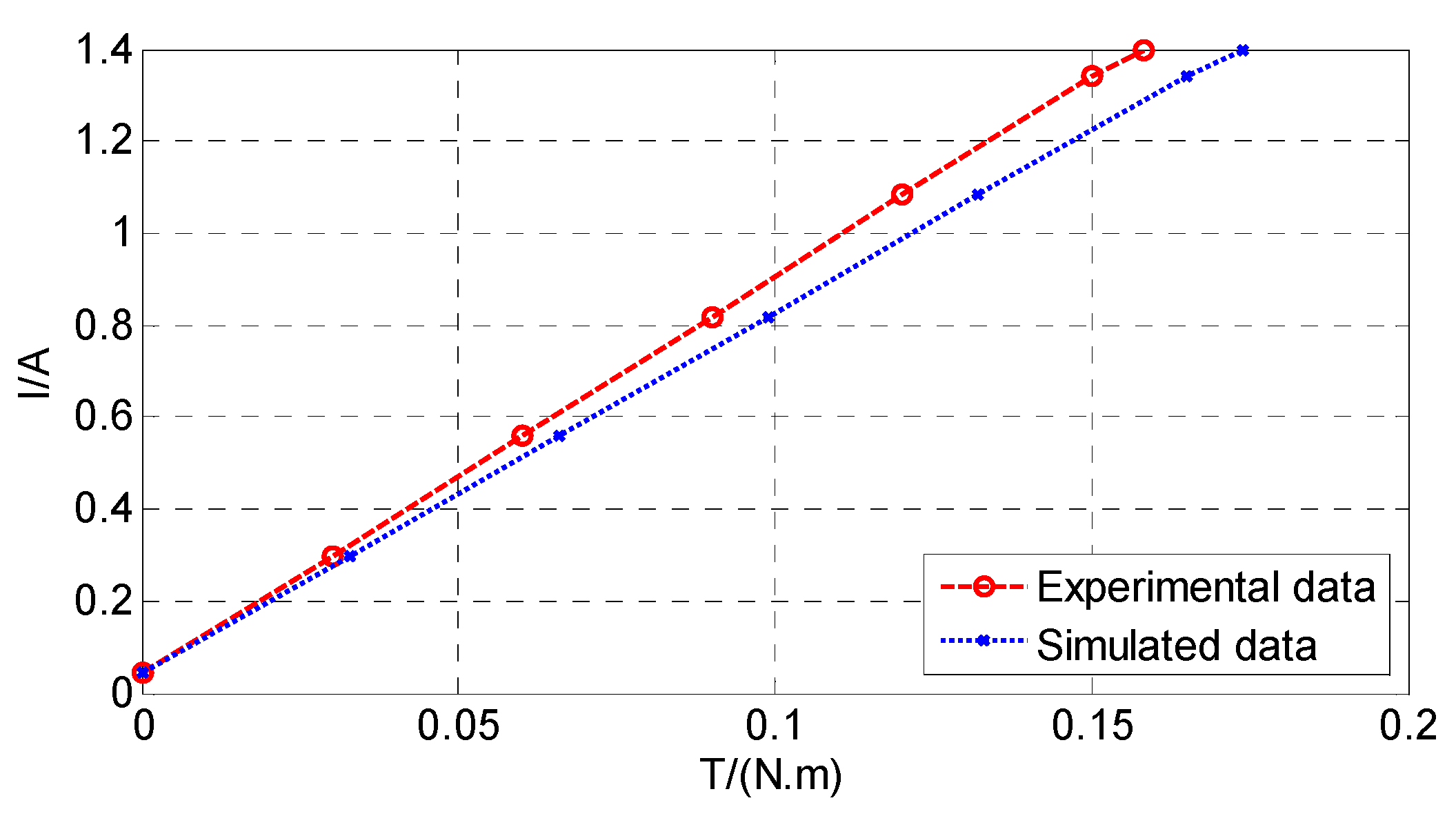
Comparison between the output torque calculation results of equivalent algorithm and the experimental results is provided in Figure 20. The six curves of Figure 19 almost coincided, and therefore it was not necessary to provide all the curves; only their average curve was taken as the representative for comparison.
The slope of the calculated curve was close to that of the experimental curve, which showed that the calculated torque constant was in good agreement with the experimental results. At the rated driving current of 1.2 A, the calculated torque was only 0.014 N·m higher than the experimental data. The comparison results prove the effectiveness of the proposed equivalent algorithm.
6. Conclusions
A fast equivalent algorithm of skewed electromotor is proposed, one that can synthesize two-dimensional electromagnetic field analysis data into three-dimensional field calculation results. The calculation model of a surface-mounted permanent magnet prototype driven by square wave current with skewed stator slot was established, and the influence of static eccentricity was studied.
Compared with the traditional magnetic circuit method commonly adopted by electromotor designers, the algorithm can consider the influence of cogging effect, winding distribution, armature reaction, and magnetic circuit saturation. Compared with the popular three-dimensional finite element method, the algorithm can greatly shorten the modelling and calculation time.
Research results indicate that the static eccentricity significantly affected the magnetic field distribution in air gap but had little influence on the average value of torque. The experimental results of prototypes prove the effectiveness of the proposed algorithm.
Funding
This research was funded by National Natural Science Foundation of China, grant number 21605039.
Conflicts of Interest
The authors declare no conflict of interest. The funders had no role in the design of the study; in the collection, analyses, or interpretation of data; in the writing of the manuscript; or in the decision to publish the results.
References
- Zhang, X.; Zhang, W.; Liang, X.; Lu, P. Performance analysis and comparison for two topologies of flux-switching permanent magnet machine. China Electrotech. Soc. Trans. Electr. Mach. Syst. 2020, 4, 190–197. [Google Scholar] [CrossRef]
- Zhu, G.; Liu, X.; Li, L.; Chen, H.; Zhu, J. Coupled electromagnetic-thermal-fluidic analysis of permanent magnet synchronous machines with a modified model. China Electrotech. Soc. Trans. Electr. Mach. Syst. 2019, 3, 204–209. [Google Scholar] [CrossRef]
- Li, W.; Cheng, M. Investigation of influence of winding structure on reliability of permanent magnet machines. China Electrotech. Soc. Trans. Electr. Mach. Syst. 2020, 4, 87–95. [Google Scholar] [CrossRef]
- Sun, T.; Liu, X.; Zou, Y.; Huang, C.; Liang, J. Design and optimization of a mechanical variable-leakage-flux interior permanent magnet machine with auxiliary rotatable magnetic poles. China Electrotech. Soc. Trans. Electr. Mach. Syst. 2021, 5, 21–29. [Google Scholar] [CrossRef]
- Tong, W.; Dai, S.; Li, S.; Li, J.; Tang, R. Modeling and Analysis of Axial Flux Permanent Magnet Machines with Coexistence of Rotor Radial Deviation and Angular Eccentricity. IEEE Trans. Energy Convers. 2020, 35, 2181–2190. [Google Scholar] [CrossRef]
- Wang, W.; Zheng, P.; Wang, M.; Liu, Y.; Fu, Z.; Sui, Y. Demagnetization and Permanent-Magnet Minimization Analyses of Less-Rare-Earth Interior Permanent-Magnet Synchronous Machines Used for Electric Vehicles. IEEE Trans. Magn. 2018, 54, 1–5. [Google Scholar] [CrossRef]
- Ciceo, S.; Chauvicourt, F.; Martis, J.G.C. PMASynRM system-level NVH model with eccentricity. In Proceedings of the 2020 IEEE Transportation Electrification Conference & Expo (ITEC), Chicago, IL, USA, 23–26 June 2020; pp. 82–86. [Google Scholar] [CrossRef]
- Park, Y.; Fernandez, D.; Bin Lee, S.; Hyun, D.; Jeong, M.; Kommuri, S.K.; Cho, C.; Reigosa, D.D.; Briz, F. Online Detection of Rotor Eccentricity and Demagnetization Faults in PMSMs Based on Hall-Effect Field Sensor Measurements. IEEE Trans. Ind. Appl. 2019, 55, 2499–2509. [Google Scholar] [CrossRef]
- Ojaghi, M.; Mohammadi, M. Unified Modeling Technique for Axially Uniform and Nonuniform Eccentricity Faults in Three-Phase Squirrel Cage Induction Motors. IEEE Trans. Ind. Electron. 2017, 65, 5292–5301. [Google Scholar] [CrossRef]
- Echeverria, J.J.R.; Da Silva, P.V.V.; Bortoni, E.D.C. Analysis of Orbital Eccentricity and UMP in Large Salient Pole Synchronous Machines. IEEE Trans. Ind. Appl. 2019, 55, 4715–4722. [Google Scholar] [CrossRef]
- Lee, H.-K.; Shin, K.-H.; Bang, T.-K.; Nah, J.-H.; Choi, J.-Y. Experimental Verification and Analytical Study of Influence of Rotor Eccentricity on Electromagnetic Characteristics of Permanent Magnet Machine. IEEE Trans. Appl. Supercond. 2020, 30, 1–5. [Google Scholar] [CrossRef]
- Kim, H.; Posa, A.; Nerg, J.; Heikkinen, J.; Sopanen, J.T. Analysis of Electromagnetic Excitations in an Integrated Centrifugal Pump and Permanent Magnet Synchronous Motor. IEEE Trans. Energy Convers. 2019, 34, 1759–1768. [Google Scholar] [CrossRef]
- Lasjerdi, H.; Nasiri-Gheidari, Z.; Tootoonchian, F. Online Static/Dynamic Eccentricity Fault Diagnosis in Inverter-Driven Electrical Machines Using Resolver Signals. IEEE Trans. Energy Convers. 2020, 35, 1973–1980. [Google Scholar] [CrossRef]
- Aggarwal, A.; Allafi, I.M.; Strangas, E.G.; Agapiou, J.S. Off-Line Detection of Static Eccentricity of PMSM Robust to Machine Operating Temperature and Rotor Position Misalignment Using Incremental Inductance Approach. IEEE Trans. Transp. Electrif. 2021, 7, 161–169. [Google Scholar] [CrossRef]
- Shin, J.; Park, Y.; Bin Lee, S. Flux-Based Detection and Classification of Induction Motor Eccentricity, Rotor Cage, and Load Defects. IEEE Trans. Ind. Appl. 2021, 57, 2471–2480. [Google Scholar] [CrossRef]
- Wang, S.; Hong, J.; Sun, Y.; Cao, H. Effect Comparison of Zigzag Skew PM Pole and Straight Skew Slot for Vibration Mitigation of PM Brush DC Motors. IEEE Trans. Ind. Electron. 2019, 67, 4752–4761. [Google Scholar] [CrossRef]
- Shi, Z.; Sun, X.; Cai, Y.; Yang, Z.; Lei, G.; Guo, Y.; Zhu, J. Torque Analysis and Dynamic Performance Improvement of a PMSM for EVs by Skew Angle Optimization. IEEE Trans. Appl. Supercond. 2019, 29, 1–5. [Google Scholar] [CrossRef]
- Ueda, Y.; Takahashi, H. Transverse-Flux Motor Design with Skewed and Unequally Distributed Armature Cores for Reducing Cogging Torque. IEEE Trans. Magn. 2017, 53, 1–5. [Google Scholar] [CrossRef]
- Jo, I.-H.; Lee, H.-W.; Jeong, G.; Ji, W.-Y.; Park, C.-B. A Study on the Reduction of Cogging Torque for the Skew of a Magnetic Geared Synchronous Motor. IEEE Trans. Magn. 2019, 55, 1–5. [Google Scholar] [CrossRef]
- Wu, X.; Zhu, Z.Q.; Wu, Z.; Liu, T.; Li, Y. Analysis and Suppression of Rotor Eccentricity Effects on Fundamental Model Based Sensorless Control of Permanent Magnet Synchronous Machine. IEEE Trans. Ind. Appl. 2020, 56, 4896–4905. [Google Scholar] [CrossRef]
- Tong, W.; Li, S.; Pan, X.; Wu, S.; Tang, R. Analytical Model for Cogging Torque Calculation in Surface-Mounted Permanent Magnet Motors With Rotor Eccentricity and Magnet Defects. IEEE Trans. Energy Convers. 2020, 35, 2191–2200. [Google Scholar] [CrossRef]
- Hu, Y.; Wei, H.; Chen, H.; Sun, W.; Zhao, S.; Li, L. Vibration Study of Permanent Magnet Synchronous Motor Base on Static Eccentricity Model. In Proceedings of the 2019 22nd International Conference on Electrical Machines and Systems (ICEMS), Harbin, China, 11–14 August 2019; pp. 1–5. [Google Scholar] [CrossRef]
- Ito, F.; Takeuchi, K.; Kotsugai, T.; Matsushita, M. A Study on Asymmetry of Electromagnetic Force Modes of Permanent Magnet Synchronous Motors With Rotor Eccentricity. IEEE Trans. Magn. 2021, 57, 1–6. [Google Scholar] [CrossRef]
- Abdi, S.; Abdi, E.; Toshani, H.; McMahon, R. Vibration Analysis of Brushless Doubly Fed Machines in the Presence of Rotor Eccentricity. IEEE Trans. Energy Convers. 2020, 35, 1. [Google Scholar] [CrossRef]
- De Gersem, H.; D’Angelo, L.A.M. Modeling Skew by Single- and Multi-Slice 2-D Machine Models. IEEE Trans. Magn. 2021, 57, 1–4. [Google Scholar] [CrossRef]
- Hong, C.; Huang, W.; Hu, Z. Performance Calculation of a Dual Stator Solid Rotor Axial Flux Induction Motor Using the Multi-Slice and Multi-Layer Method. IEEE Trans. Magn. 2018, 55, 1–9. [Google Scholar] [CrossRef]
- Zhang, D.; Liu, T.; He, C.; Wu, T. A New 2-D Multi-Slice Time-Stepping Finite Element Method and Its Application in Analyzing the Transient Characteristics of Induction Motors under Symmetrical Sag Conditions. IEEE Access 2018, 6, 47036–47046. [Google Scholar] [CrossRef]
- Liu, T.; Jiang, M.; Zhang, D.; Zhao, H.; Shuang, F. Effect of Symmetrical Voltage Sag on Induction Motor Considering Phase-Angle Factors Based on a New 2-D Multi-Slice Time-Stepping Finite Element Method. IEEE Access 2020, 8, 75946–75956. [Google Scholar] [CrossRef]
Figure 1.
Schematic diagram of air-gap eccentricity.

Figure 2.
Ideology of equivalent algorithm: (a) a skewed electromotor is divided into several sections; (b) the whole winding conductor in the segmented skewed slot is replaced by several straight conductors.
Figure 2.
Ideology of equivalent algorithm: (a) a skewed electromotor is divided into several sections; (b) the whole winding conductor in the segmented skewed slot is replaced by several straight conductors.

Figure 3.
A charged and moving inclined conductor in harmonic magnetic field.
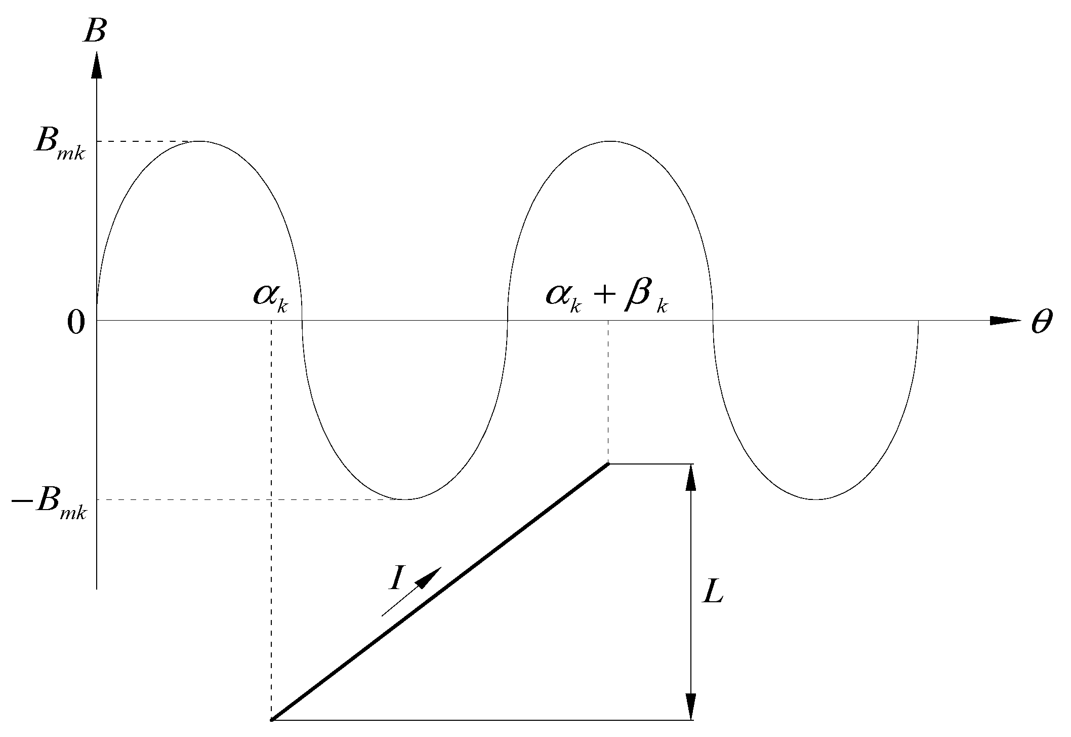
Figure 4.
Segmentation modes: (a) mode 1; (b) mode 2.
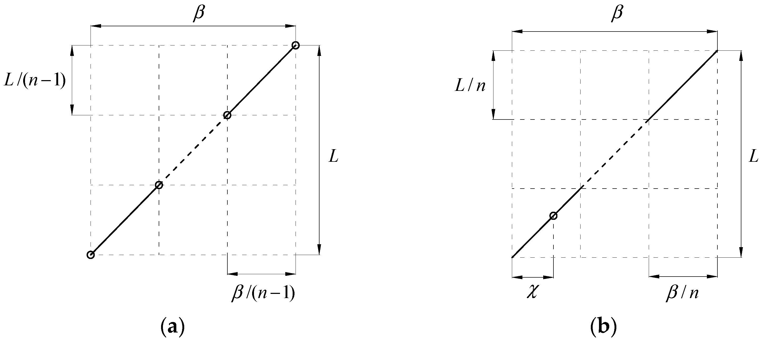
Figure 5.
Relative errors with different combinations of segment number and harmonic order.

Figure 6.
Radial cross section of the prototype: (a) stator; (b) rotor.

Figure 7.
Distribution of magnetic flux density: (a) healthy; (b) eccentric distance is 0.2 mm.

Figure 8.
Comparison of normal magnetic density waveforms of air gap in the whole circumference.
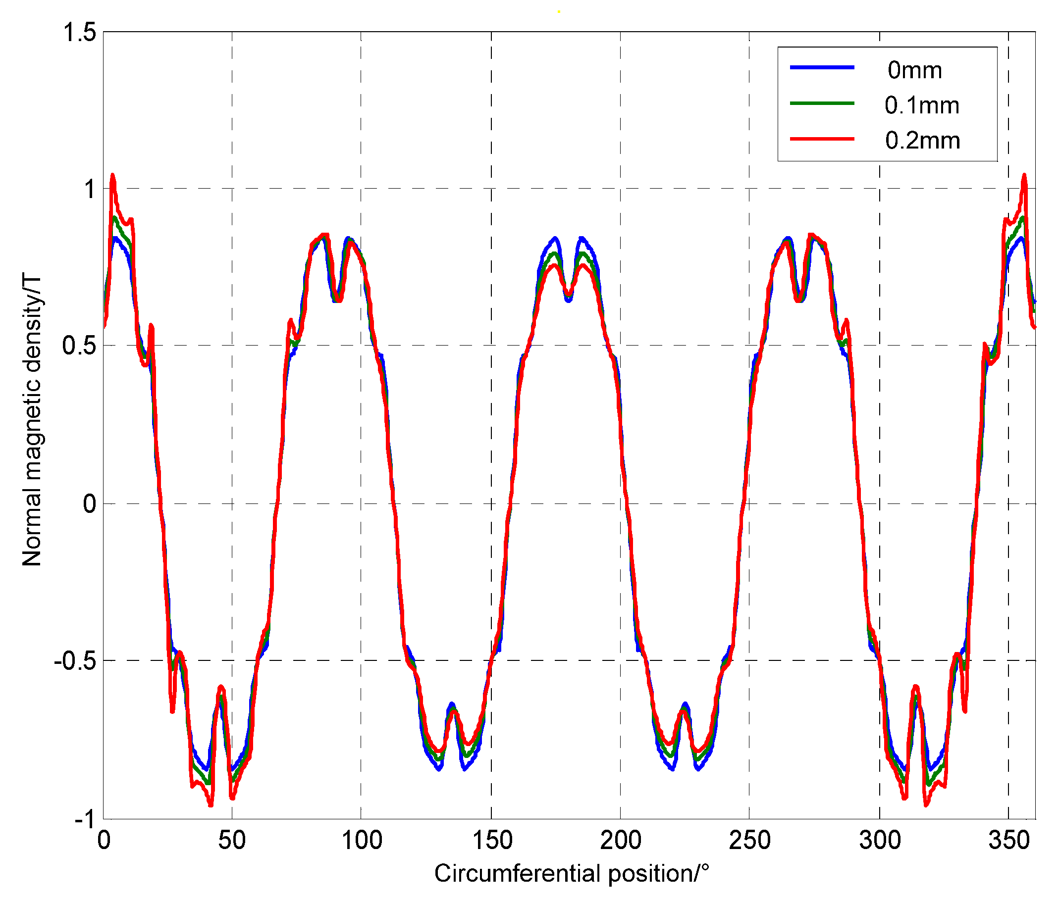
Figure 9.
Comparison of harmonic components of normal magnetic density of air gap in the whole circumference.
Figure 9.
Comparison of harmonic components of normal magnetic density of air gap in the whole circumference.
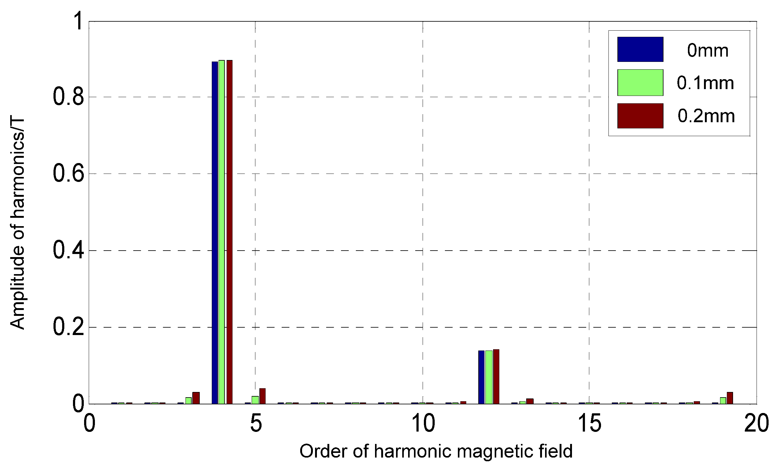
Figure 10.
EMF of winding elements when the motor rotates once.

Figure 11.
EMF of A-phase winding when the motor rotates once.
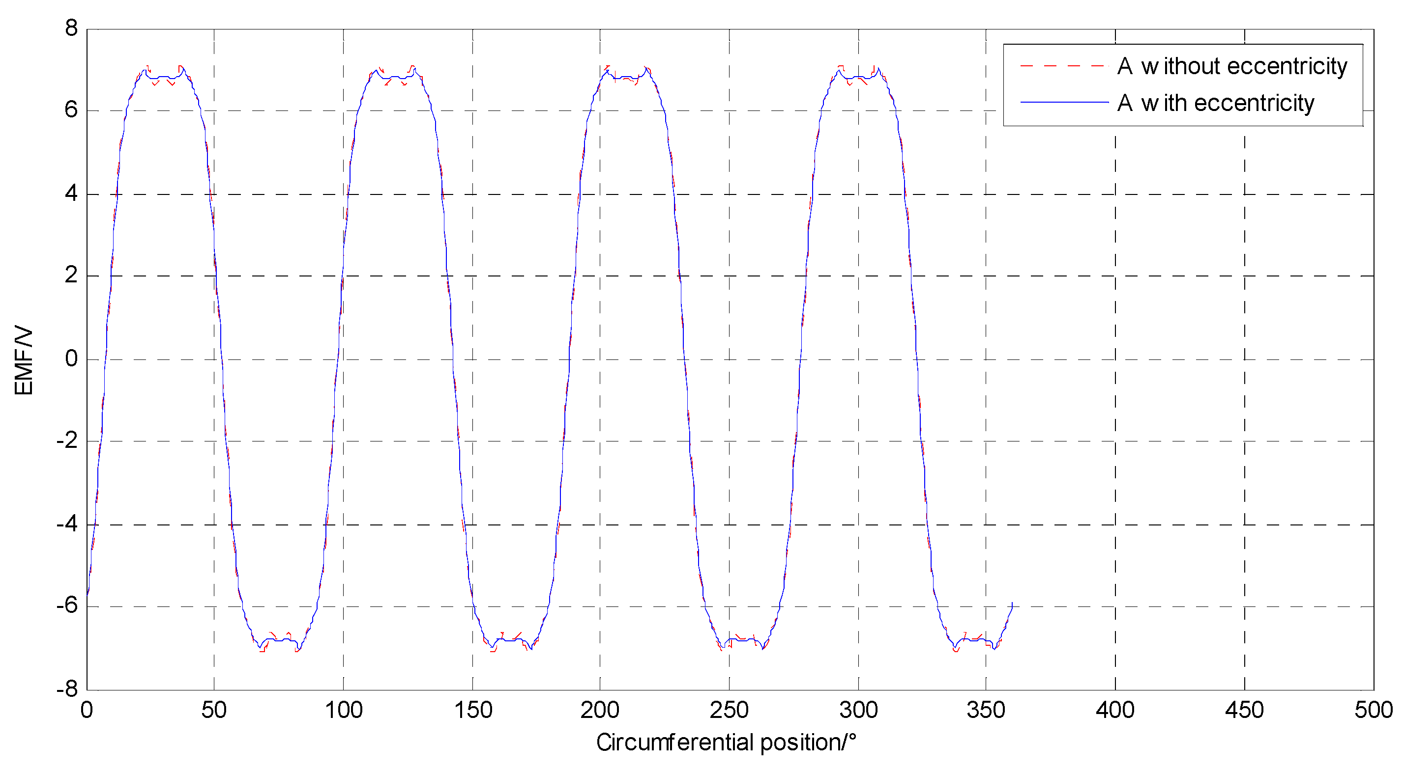
Figure 12.
Comparison of harmonic components of EMF without skew when the motor rotates once.
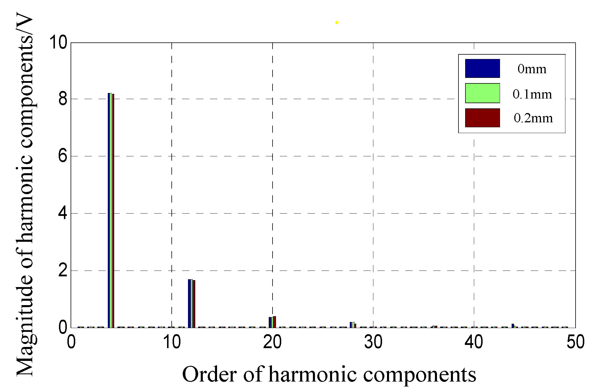
Figure 13.
Comparison of EMF waveforms without skew in a variable period.
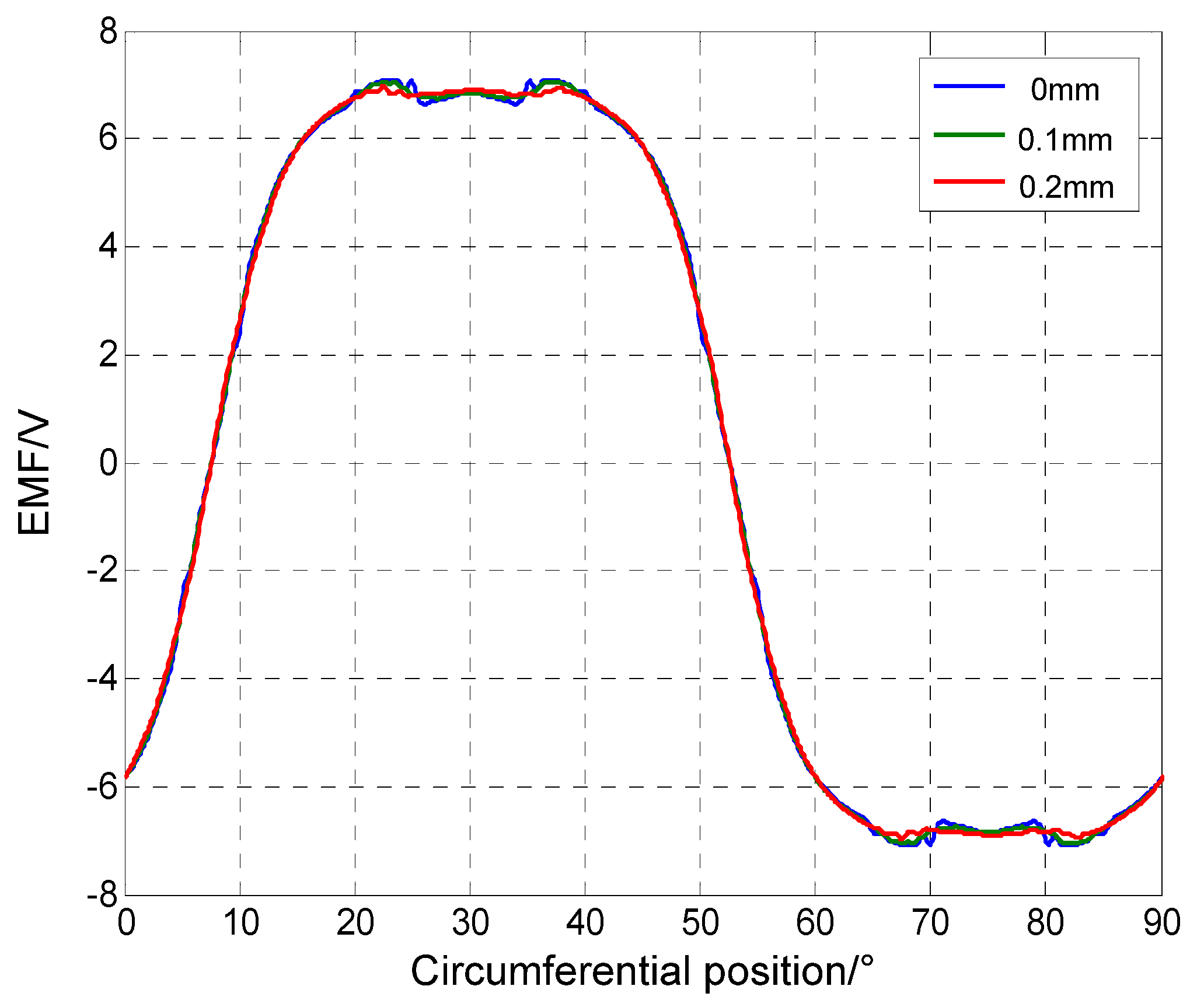
Figure 14.
Comparison of EMF waveforms with skew in a variable period.
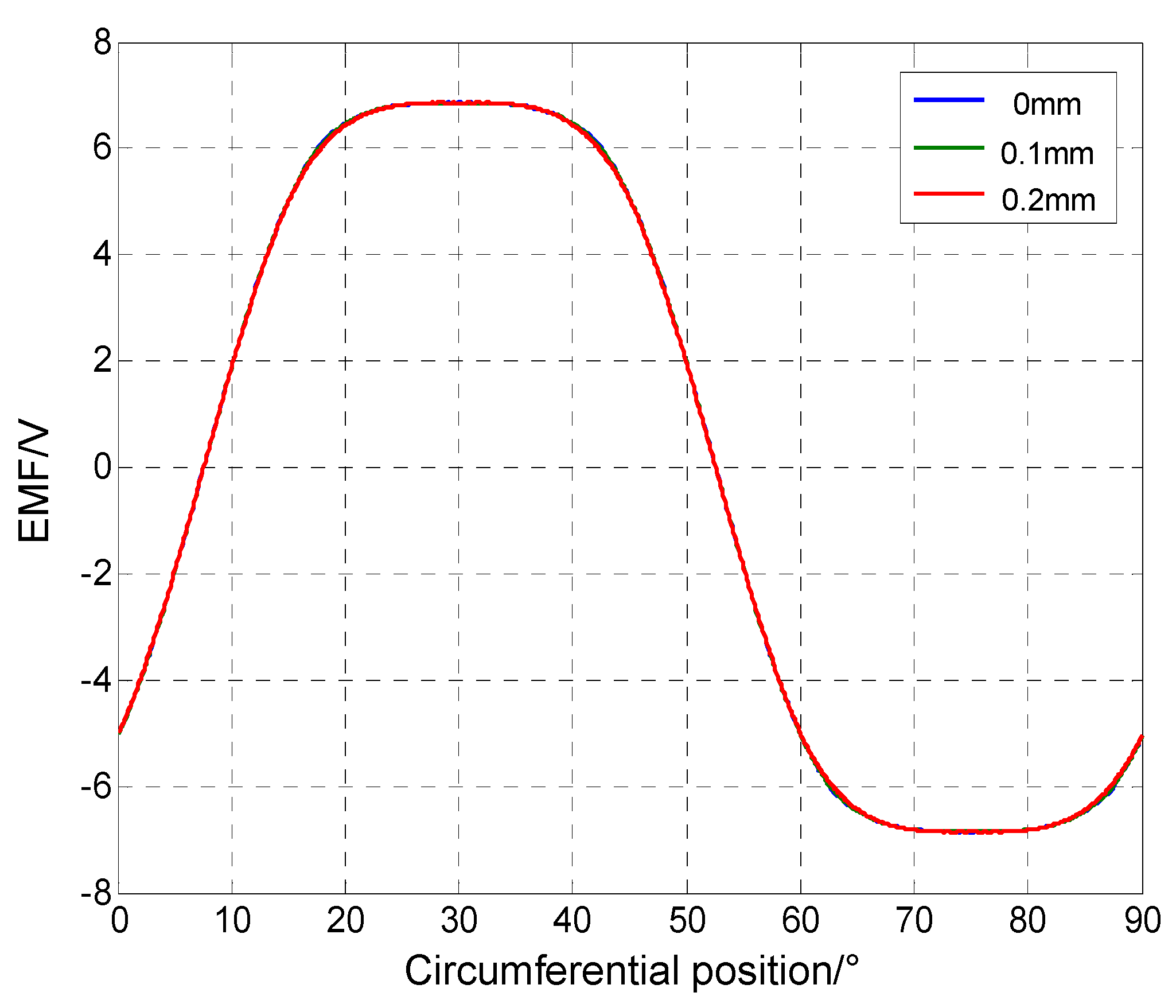
Figure 15.
Comparison of harmonic components of EMF with skew in a variable period.
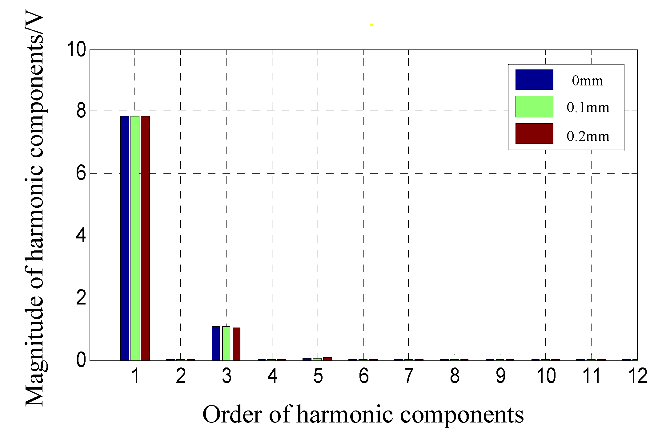
Figure 16.
Comparison of cogging torque without skew in a variable period.
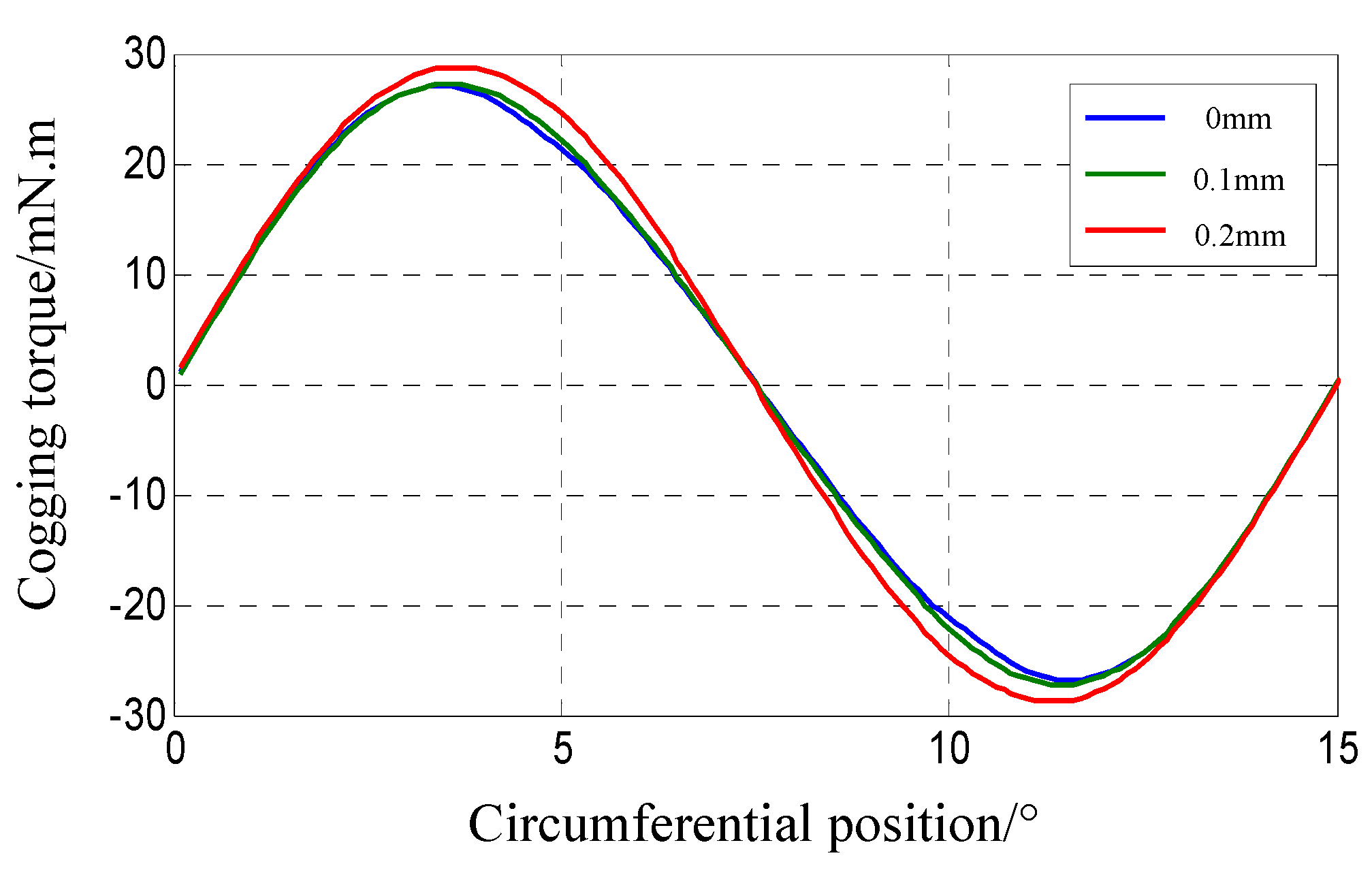
Figure 17.
Comparison of cogging torque with skew in a variable period.

Figure 18.
Photos of the experiment: (a) prototypes; (b) experimental hardware platform.

Figure 19.
Experimental data of prototypes.
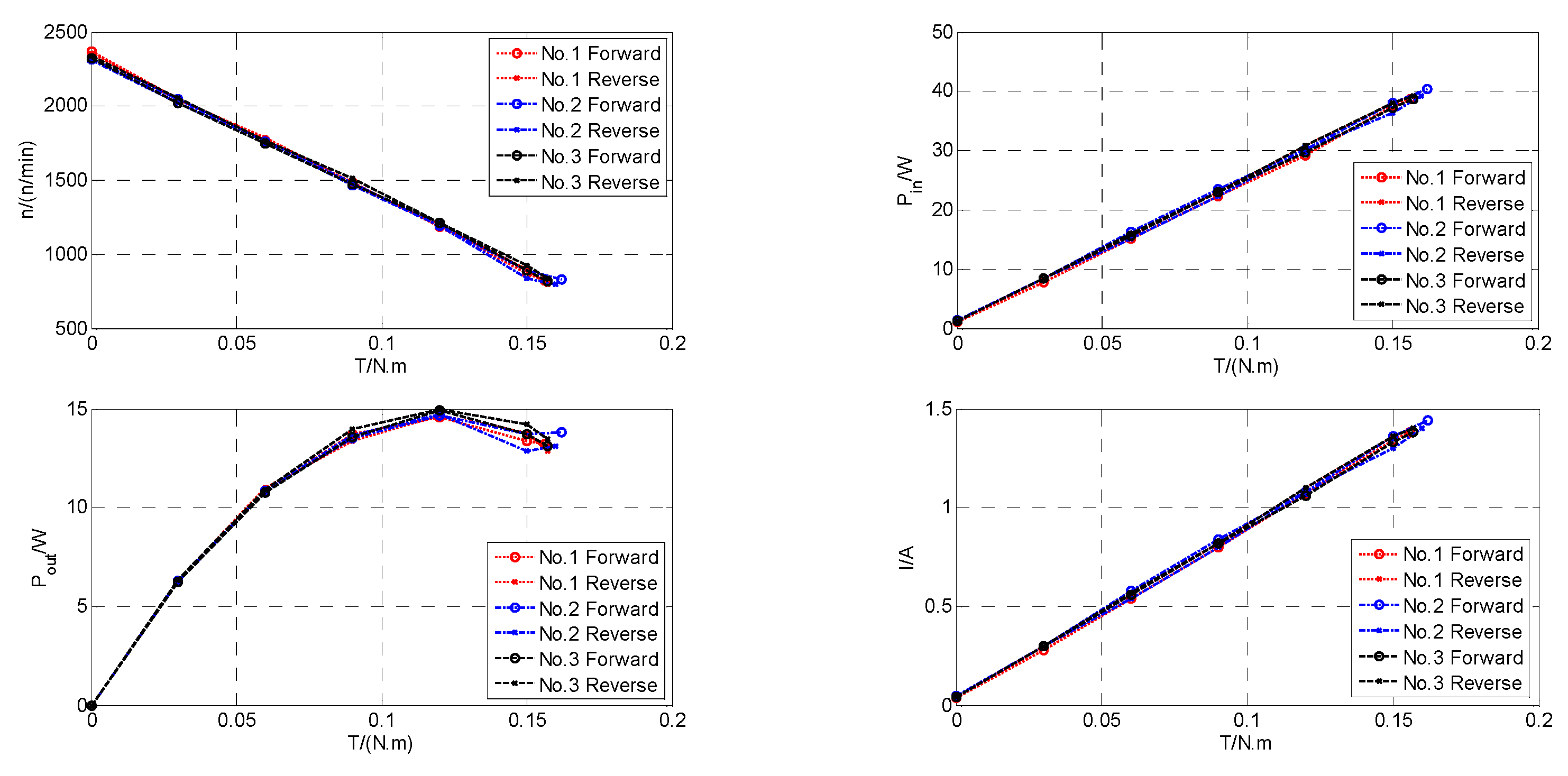
Figure 20.
Comparison between calculated and experimental data.
Publisher’s Note: MDPI stays neutral with regard to jurisdictional claims in published maps and institutional affiliations. |
© 2021 by the author. Licensee MDPI, Basel, Switzerland. This article is an open access article distributed under the terms and conditions of the Creative Commons Attribution (CC BY) license (https://creativecommons.org/licenses/by/4.0/).
Share and Cite
MDPI and ACS Style
Wang, L. Static Eccentricity Fault Analysis of Surface-Mounted Permanent Magnet Electromotor with Skewed Slots Based on 2D FEA. World Electr. Veh. J. 2021, 12, 176. https://doi.org/10.3390/wevj12040176
AMA Style
Wang L. Static Eccentricity Fault Analysis of Surface-Mounted Permanent Magnet Electromotor with Skewed Slots Based on 2D FEA. World Electric Vehicle Journal. 2021; 12(4):176. https://doi.org/10.3390/wevj12040176
Chicago/Turabian StyleWang, Li. 2021. "Static Eccentricity Fault Analysis of Surface-Mounted Permanent Magnet Electromotor with Skewed Slots Based on 2D FEA" World Electric Vehicle Journal 12, no. 4: 176. https://doi.org/10.3390/wevj12040176