
A Thrust Cooperative Control Strategy of Multiple Propulsion Motors for Distributed Electric Propulsion Aircraft

1
School of Automation, Nanjing University of Aeronautics and Astronautics, Nanjing 211106, China
2
AECC Aero Engine Control System Institute, Wuxi 214063, China
*
Author to whom correspondence should be addressed.
World Electr. Veh. J. 2021, 12(4), 199; https://doi.org/10.3390/wevj12040199
Submission received: 26 August 2021
/
Revised: 11 October 2021
/
Accepted: 18 October 2021
/
Published: 19 October 2021
(This article belongs to the Special Issue Towards Intelligent E-Mobility—Selected Papers from The 34th International Electric Vehicles Symposium and Exhibition (Nanjing, China))
Abstract
:This paper presents a thrust cooperative control strategy of multiple propulsion motors for distributed electric propulsion aircraft. The control strategy can keep the propulsion motors running synchronously when the aircraft is flying in a straight line; at the same time, when the aircraft needs to turn, the yaw moment is generated by changing the speed of the propulsion motors on both sides, so as to achieve the given yaw angle of the aircraft. In order to verify the control strategy, the paper also carries out simulation and experimental verification, and the results show that the cooperative control strategy is feasible.
1. Introduction
In order to further improve the flight performance of the aircraft and reduce the fuel consumption of the aircraft, researchers began to study electric propulsion systems on the basis of electric propulsion aircraft to explore high-performance electric propulsion technology [1]. Distributed electric propulsion technology can effectively reduce the weight of the system and improve the flexibility of system energy control because it decomposes the high-power propulsion system of traditional electric propulsion aircraft into small power propulsion systems with equal total power, which are distributed in different positions of the fuselage [2,3].
The architecture of the distributed electric propulsion system is shown in Figure 1 [4]. In this paper, four propulsion motors are studied. Among them, motor 1 and motor 2 represent the propulsion motors on the left side of the fuselage, and motor 3 and motor 4 represent the propulsion motors on the right side of the fuselage.
The motor has the characteristics of relative scale independence, that is, after a high-power motor system is decomposed into several low-power motor systems with the same total power, the power density and efficiency of the whole system are basically unchanged [5]. This makes it possible to use multiple relatively small power motors to drive smaller diameter fans instead of super large diameter fans. This can effectively improve the bypass ratio and efficiency of the system fault-tolerant performance, and the energy control of the system is more flexible, so as to further improve the performance of the power plant and improve the fuel consumption rate [6]. In addition, the small fans can be more easily integrated into the fuselage, making the airplane more aerodynamically efficient, improving the airplane flight performance and fuel consumption in another way [7].
According to different flight conditions, when the airplane flies in a straight line, each propulsion motor is required to work at the same speed to output the same thrust. This requires good speed synchronization of each propulsion motor. A cross-coupling control strategy is proposed in [8], which can make another motor change its speed synchronously when the speed of one motor is suddenly changed due to disturbance. However, this control strategy can only be applied to the system with two motors, not to the system with more than two motors. The relative coupling control proposed in [9] is improved on this basis, and can be applied to systems with more than two motors to keep them synchronized. However, the synchronization of this control strategy is not very ideal. When the speed changes suddenly, the speed difference of each motor is large. In order to further improve its synchronization performance, an improved control strategy is proposed in this paper. When the aircraft needs to turn, the authors of [10] propose a yaw control strategy using ailerons; on this basis, a new yaw control strategy is proposed, which no longer needs ailerons to realize yaw control, so as to simplify the mechanical structure of the plane.
2. Thrust Cooperative Control Strategy
The distributed electrical propulsion airplane is propelled by multiple low-power thrusters located at various points in the fuselage. Hence, we can make full use of this feature and adopt an appropriate control strategy to make each propeller work together according to the flight conditions of the plane. This can simplify the structure of the plane and improve the flight flexibility to a certain extent [11]. The thrust of the plane is generated by the propellers driven by the propulsion motors, and the output thrust of the propeller is directly related to the speed of the propulsion motor [12]. Therefore, the research on the cooperative control of thrust of each propeller can be transformed into the research on the cooperative control of speed of each propulsion motor.
This paper mainly designs a synchronous cooperative control strategy (SCCS) and a distributed cooperative control strategy (DCCS). In the case of a straight-line flight, SCCS is adopted. When the plane needs to turn, DCCS is adopted.
2.1. Synchronous Cooperative Control Strategy
When the airplane flies in a straight line, each propeller is required to work at the same speed, so that the left and right propellers of the fuselage provide the same thrust [13]. However, due to the influence of air flow or other factors, if a propeller is disturbed and its speed changes abruptly, the thrust output of the left and right propellers may be inconsistent, resulting in the yaw of the airplane [14]. Therefore, it is necessary to adopt an appropriate control strategy to keep the propulsion motors working synchronously when the airplane is flying in a straight line.
2.1.1. Relative Coupling Control
Relative coupling control is a commonly used multi-motor cooperative control method. This control method can keep all motors running synchronously in a multi-motor system. Its structure is shown in Figure 2. The core idea of the relative coupling control structure is to subtract the speed of one motor from that of other motors to obtain a speed difference. Then, the obtained speed difference is multiplied by the speed compensation coefficient of each motor to obtain a speed compensation value signal. Finally, the speed compensation value signal is combined with the speed signal provided by the system, which is used as the given speed input signal of the motor to improve the synchronization accuracy between motors to a certain extent [15,16].
In Figure 2, nref represents the given speed of all motors, and its value is provided by the aircraft control system. In this paper, it is assumed that its value is known and remains unchanged. TLi represents the load torque of each motor, ni represents the actual speed of each motor, and yi represents the compensated speed of each motor output by the speed compensator. It can be seen from Figure 2 that the speed compensator module is the key part of the relative coupling control. Taking speed compensator 1 as an example, the structure of this module is shown in Figure 3.
Since many variables are involved in the following formulas and diagrams, all involved variables and their definitions are listed in Table 1.
In Figure 3, λi represents the speed proportional factor of motor i. When each motor works at the same speed, the value of λ is 1. kij is the feedback gain coefficient to compensate the difference of moment of inertia between the motor i and the motor j. The value can be expressed as:
where J represents the moment of inertia of the motor.
When the moment of inertia of each motor is the same, the value of kij is 1.
Therefore, when each motor works at the same speed, the speed compensation value of motor 1 is:
Similarly, the speed compensation values of motor 2, motor 3, and motor 4 are:
2.1.2. Improved Relative Coupling Control
The speed compensator is the key to relative coupling control. However, the speed compensation value is simply obtained by adding the difference of the corresponding motor speeds times the gain, without considering the change trend of motor speed, that is, its acceleration. As a result, the synchronization accuracy of this structure is not very high [15,17].
In order to improve the synchronization performance of relative coupling control, an improved relative coupling control is proposed. In this control method, an improved speed compensator is added on the basis of retaining the original speed compensator of relative coupling control. The improved speed compensator introduces the concepts of maximum speed synchronization error and maximum acceleration, and its structure is shown in Figure 4.
The improved speed compensator can be expressed as:
In the formula, kv and ka represent the velocity compensation coefficient and acceleration compensation coefficient respectively, and nerm represents the speed of the motor with the largest error from the given speed. However, excessive compensation will affect the stability of the system, so it is necessary to reasonably select the values of kv and ka.
By using the improved speed compensator together with the original speed compensator, the synchronization accuracy of the cooperative control strategy can be further improved. After use together, the given speed after compensation can be expressed as:
2.2. Distributed Cooperative Control Strategy
When the aircraft needs to turn, the traditional aircraft turns by adjusting the aileron or using the vectoring nozzle [18]. However, the distributed electric propulsion aircraft has multiple propulsion motors on the left and right sides of the fuselage, so it can generate yaw moment by adjusting the speeds of the motors on the left and right sides. Therefore, it does not need to rely on ailerons or vectoring nozzles, which can simplify the mechanical structure of the plane [19]. For example, when the plane needs to turn left, the right motors accelerate while the left motors decelerate, so that the system generates a yaw moment to the left, so as to realize the left turn, and vice versa when turning right. This is the core idea of distributed cooperative control proposed in this paper.
The block diagram of distributed cooperative control is shown in Figure 5.
Firstly, the output thrust of each propulsion motor is calculated according to the speed of each propulsion motor, and then the yaw moment is calculated according to the position of each propulsion motor and the thrust output by the propeller Fi [20], so as to calculate the steering angular velocity by Equation (8):
where, B is the steering moment of inertia of the aircraft, M is the yaw moment, and ω is the steering angular velocity.
Then, the actual yaw angle can be calculated by Equation (9):
The above is the process of calculating the yaw angle by the yaw angle calculator.
After the actual yaw angle, is obtained, depending on the difference between the given yaw angle and the actual yaw angle, the speed compensation command can be obtained through the yaw angle controller. Then, the speed compensation command allocated to the left and right propulsion motors is obtained through the speed distributor. The speed distributor is equivalent to a coefficient matrix T, then the compensation speed of motor i output by the speed distributor can be obtained by Equation (10):
The values L1, L2, L3, and L4 of the coefficient matrix shall be selected according to the position of the fuselage where each propulsion motor is located.
Finally, the original speed instruction and the obtained speed compensation instruction of each propulsion motor are transmitted to each propulsion motor controller to realize the aircraft steering. The given speed after compensation can be expressed as:
The thrust cooperative control strategy is constituted by combining the synchronous cooperative control with the distributed cooperative control proposed above.
3. Results
3.1. Simulation Verification
In order to verify the feasibility of the proposed thrust cooperative control strategy, the synchronous cooperative control and distributed cooperative control are simulated respectively in this paper. The simulation is carried out in MATLAB/Simulink. The schematic diagram of the system is shown in Figure 6: judge which flight state the airplane is in according to whether the yaw angle, θ, is 0, and add the speed compensation command of each propulsion motor output in this state to the given speed, nref. The load simulation motor is coaxially connected with the propulsion motor to simulate the load characteristics of the propeller. The electric energy generated by the load simulation motors is transmitted to a 540 V DC bus. Key parameters are shown in Table 2.
3.1.1. Simulation of Synchronous Cooperative Control
Firstly, the traditional relative coupling control is simulated. The models of the four propulsion motors are the same. The four propulsion motors are assigned a speed of 1500 rpm, and initially all work under the rated propeller load. At 4 s, a load disturbance of 40 Nm is added to one of the motors, while the load of the other motors remains unchanged. The speed difference waveform between the disturbed motor and the rest of the motors is shown in Figure 7.
It can be seen from the waveform that when one of the motors is disturbed at 4 s, the other motors can also respond to the disturbance. The maximum speed difference between the disturbed motor and the undisturbed motors is about 12 rpm.
Then, the improved relative coupling control is simulated. The four propulsion motors are still assigned a speed of 1500 rpm, and initially all work under the rated propeller load. At 4 s, a load disturbance of 40 Nm is added to one of the motors, while the load of the other motors remains unchanged. The speed difference waveform between the disturbed motor and the rest of the motors is shown in Figure 8.
It can be seen from the waveform that when one of the motors is disturbed at 4 s, the other motors can also respond to the disturbance. The maximum speed difference between the disturbed motor and the undisturbed motors is about 6 rpm, obviously less than 12 rpm, when using the relative coupling control. Therefore, the synchronization performance of the multiple motor system can be further improved by using the improved relative coupling control.
3.1.2. Simulation of Distributed Cooperative Control
When the aircraft needs to turn, the DCCS is adopted. A positive yaw angle represents that the plane turns right, and a negative yaw angle represents that the plane turns left. At 4 s, the aircraft turns 30 degrees to the right, and the yaw angle of the aircraft and the speed waveform of the propulsion motors on the left and right sides of the fuselage are shown in Figure 9.
It can be seen from the waveforms that when the aircraft needs to turn 30 degrees right at 4 s, the left motors accelerate first and then decelerate, and the right motors decelerate first and then accelerate. When the steering is completed, the speed of the motors on both sides returns to 1500 rpm.
When the aircraft needs to turn 60 degrees to the left at 4 s, the yaw angle of the aircraft and the speed waveform of the propulsion motors on the left and right sides of the fuselage are shown in Figure 10.
It can be seen from the waveforms that when the plane needs to turn 60 degrees left at 4 s, the right motors accelerate first and then decelerate, and the left motors decelerate first and then accelerate. When the steering is completed, the speed of the motors on both sides returns to 1500 rpm.
Therefore, the DCCS can realize the left and right turns of the plane without the need for ailerons.
3.2. Experimental Verification
In addition, based on the simulation, an experimental platform was built to verify the feasibility of the thrust cooperative control strategy. The experimental platform is shown in Figure 11. The experimental platform mainly includes four propulsion motors and load simulation motors, cabinets for motor controllers, a water-cooling machine, and a PC. Load simulation motors are mainly used to simulate propeller load.
3.2.1. Experiment of Synchronous Cooperative Control
Firstly, the experimental verification of synchronous cooperative control was carried out. The speed of the four motors is 1530 rpm, and the load is rated propeller load. At 10 s, a 40 Nm disturbance was suddenly added to a motor, and the disturbance disappeared at 27 s and returned to the rated load. The speed waveforms of each motor under the relative coupling control are shown in Figure 12. The speed waveforms of each motor under the improved relative coupling control are shown in Figure 13. The load torque waveforms of each motor are shown in Figure 14.
It can be seen from the experimental waveforms that when a motor in the system is disturbed and the speed changes suddenly, if the relative coupling control mode is adopted, the speed synchronization error of each motor is large. When the improved relative coupling control is adopted, the speed synchronization error between motors is significantly reduced. Therefore, the SCCS can make the system have better synchronization performance.
3.2.2. Experiment of Distributed Cooperative Control
Then, the distributed cooperative control was verified. In the experiment, a control mode similar to the rudder of an aircraft was designed. The user can drag the rudder in real-time to realize the steering. When the rudder is pulled to the left, it means turning left; at this time, the left motors decelerate, and the right motors accelerate. When the rudder is pulled to the right, it means turning right; at this time, the right motors decelerate, and the left motors accelerate. When the rudder is pulled back to the middle, it means flying in a straight line, and the left and right motors return to the same speed.
The rudder was dragged to the left at 18 s and back to the middle at 32 s. The speed waveforms of the four motors are shown in Figure 15.
It can be seen from the experimental waveforms that when the rudder is dragged to the left, the motors on the left decelerate and the motors on the right accelerate, so as to realize the left turn of the aircraft. Therefore, the distributed cooperative control can realize the aircraft steering by changing the speeds of the propulsion motors on the left and right sides of the plane.
4. Conclusions
In this paper, a thrust cooperative control strategy of multiple propulsion motors for distributed electric propulsion aircraft was proposed, and the feasibility of the control strategy was verified by simulation and experiment. Through the research of this paper, the following conclusions were obtained:
- The proposed SCCS in this paper can not only be applied to the system with more than two motors, but also has stronger synchronization performance than the relative coupling control. In this way, it can ensure that the airplane will not yaw due to the inconsistency of left and right thrust when flying in a straight line.
- The proposed DCCS can make the airplane realize yaw control without relying on ailerons or vectoring nozzles, but by adjusting the speeds of motors on both sides. Thus, the mechanical structure of the airplane is simplified.
- The combination of the two control strategies can realize the straight-line flight and yaw control of the airplane.
However, this multiple motor cooperative control strategy involves the selection of more coefficient values. In the actual selection of coefficient values, it is necessary to comprehensively consider various requirements of the system.
Author Contributions
L.W. wrote the article and was responsible for the models and simulations; L.W. and H.L. were responsible for the experiments; T.Y., X.Z. and F.B. were responsible for the data analysis. All authors have read and agreed to the published version of the manuscript.
Funding
This research received no external funding.
Conflicts of Interest
The authors declare no conflict of interest.
References
- Karen, D.; Pj, N.; Catherine, J.; Stuart, G. A review of turboelectric distributed propulsion technologies for N+3 aircraft electrical systems. In Proceedings of the 48th International Universities’ Power Engineering Conference (UPEC), Dublin, Ireland, 2–5 September 2013. [Google Scholar] [CrossRef] [Green Version]
- Hyun, D.K.; James, L.F.; Michael, T.T. Turboelectric distributed propulsion benefits on the N3-X vehicle. Aircr. Eng. Aerosp. Technol. 2014, 86, 558–561. [Google Scholar]
- Yang, X.; Li, W.; Wang, Y. Research on Aerodynamic Shape Design Scheme of a Distributed Propeller Transport Aircraft and Its Slipstream Effect. J. Northwestern Polytech. Univ. 2019, 37, 361–368. [Google Scholar] [CrossRef]
- Van, E.N.; Alazard, D.; Dll, C. Co-design of aircraft vertical tail and control laws with distributed electric propulsion and flight envelop constraints. CEAS Aeronaut. J. 2021, 12, 101–113. [Google Scholar]
- Perry, A.T.; Ansell, P.J.; Kerho, M. Aero-Propulsive and Propulsor Cross-Coupling Effects on a Distributed Propulsion System. In Proceedings of the 2018 AIAA Aerospace Sciences Meeting, Kissimmee, FL, USA, 8–12 January 2018. [Google Scholar]
- Moore, M.D.; Fredericks, B. Misconceptions of Electric Propulsion Aircraft and Their Emergent Aviation Markets. 52nd Aerospace Sciences Meeting; AIAA: National Harbor, MD, USA, 2014. [Google Scholar]
- Jun, H.; Yang, F. Development and challenges of electric aircraft with new energies. Acta Aeronaut. Astronaut. Sin. 2016, 37, 57–68. [Google Scholar]
- Fang, H.; Wang, C. Cross-coupling synchronous control of dual-motor networked motion control system. In Proceedings of the 2017 36th Chinese Control Conference (CCC), Dalian, China, 26–28 July 2017. [Google Scholar]
- Wang, P. The Immune Single Neuron PID Synchronization Control Based on Relative Coupling. J. Chang. Inst. Technol. 2018, 19, 30–34. [Google Scholar]
- Qu, X.; Zhang, W.; Shi, J. A novel yaw control method for flying-wing aircraft in low speed regime. Aerosp. Sci. Technol. 2017, 69, 636–649. [Google Scholar] [CrossRef]
- Wang, K.; Zhou, Z.; Fan, Z. Aerodynamic design of tractor propeller for high-performance distributed electric propulsion aircraft. Chin. J. Aeronaut. 2021, 34, 20–35. [Google Scholar] [CrossRef]
- Pelz, P.F.; Leise, P.; Meck, M. Sustainable aircraft design—A review on optimization methods for electric propulsion with derived optimal number of propulsors. Prog. Aerosp. Sci. 2021, 100714. [Google Scholar] [CrossRef]
- Berg, F.; Palmer, J.; Miller, P. HTS electric system for a distributed propulsion aircraft. IEEE Trans. Appl. Supercond. 2015, 25, 1–5. [Google Scholar] [CrossRef]
- Loureiro, E.V.; Oliveira, N.L.; Hallak, P.H. Evaluation of low fidelity and CFD methods for the aerodynamic performance of a small propeller. Aerosp. Sci. Technol. 2021, 108, 106402. [Google Scholar] [CrossRef]
- Tingna, S.; Hao, L.; Qiang, G. An improved relative coupling control structure for multi-motor speed synchronous driving system. IET Electr. Power Appl. 2016, 10, 451–457. [Google Scholar]
- Li, C.; Wang, C.; Pan, J. Improved Relative Coupling Control with Second-Order Consensus Compensation for Multi-PMSMs. In Proceedings of the 2019 22nd International Conference on Electrical Machines and Systems (ICEMS), Harbin, China, 11–14 August 2019. [Google Scholar]
- Miao, X.; Wang, S.; Han, L. Single Neuron PID Synchronization Control Strategy in Multi-motor Systems Based on the Relative Coupling Control. Micromotors 2020, 42, 44–47. [Google Scholar]
- Nicholas, J.C. Pathfinder and the Development of Solar Rechargeable Aircraft; Carnegie Mellon University: Pittsburgh, PA, USA, 2002. [Google Scholar]
- Fang, Z. Aircraft Flight Dynamics; Beijing University of Aeronautics and Astronautics Press: Beijing, China, 2005; ISBN 978-7-8107-7670-7. [Google Scholar]
- Jones, C.E.; Norman, P.J.; Galloway, S.J. Comparison of candidate architectures for future distributed propulsion aircraft. IEEE Trans. Appl. Supercond. 2016, 26, 5202705. [Google Scholar] [CrossRef] [Green Version]
Figure 1.
Architecture of the distributed electric propulsion system.
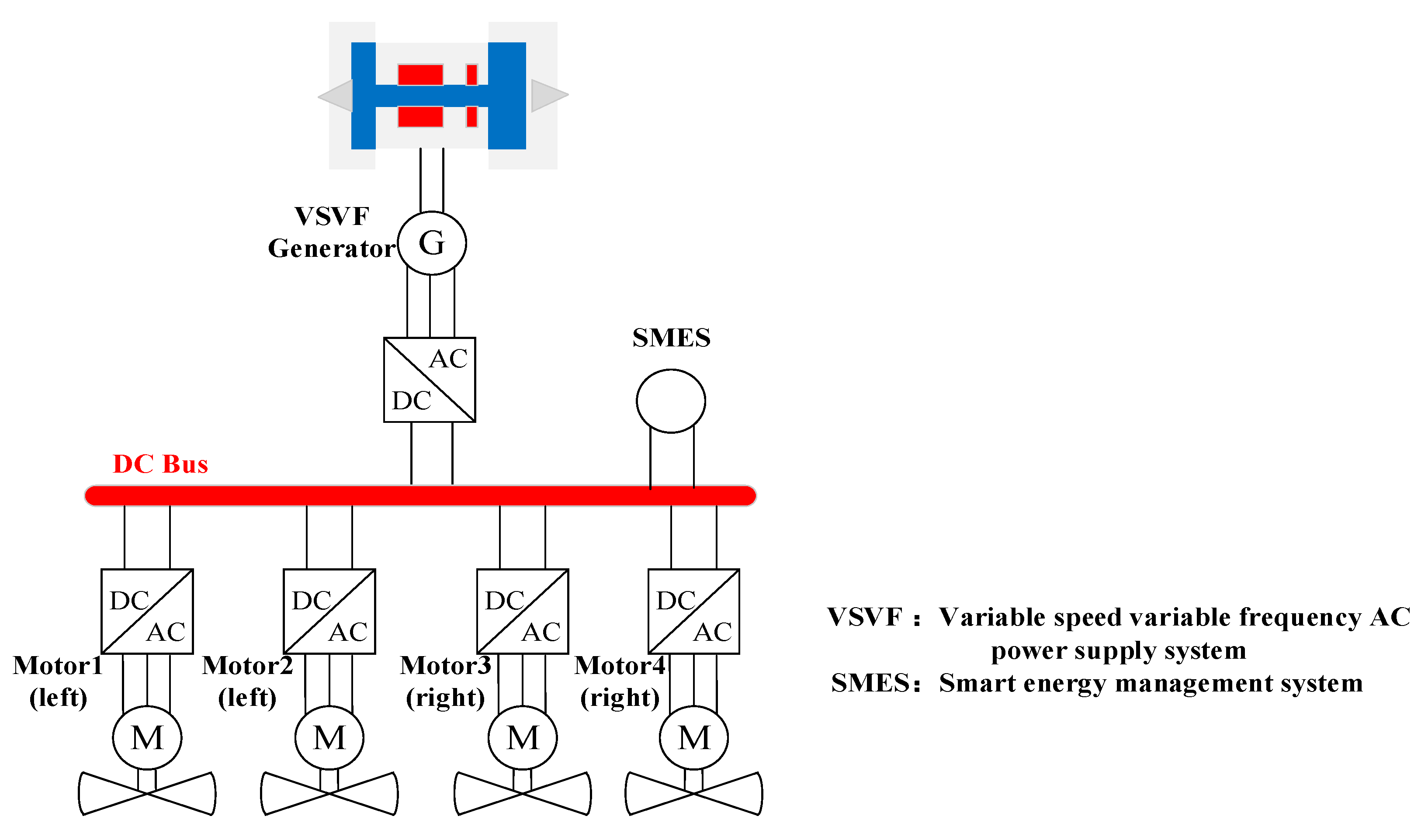
Figure 2.
Structure of relative coupling control.
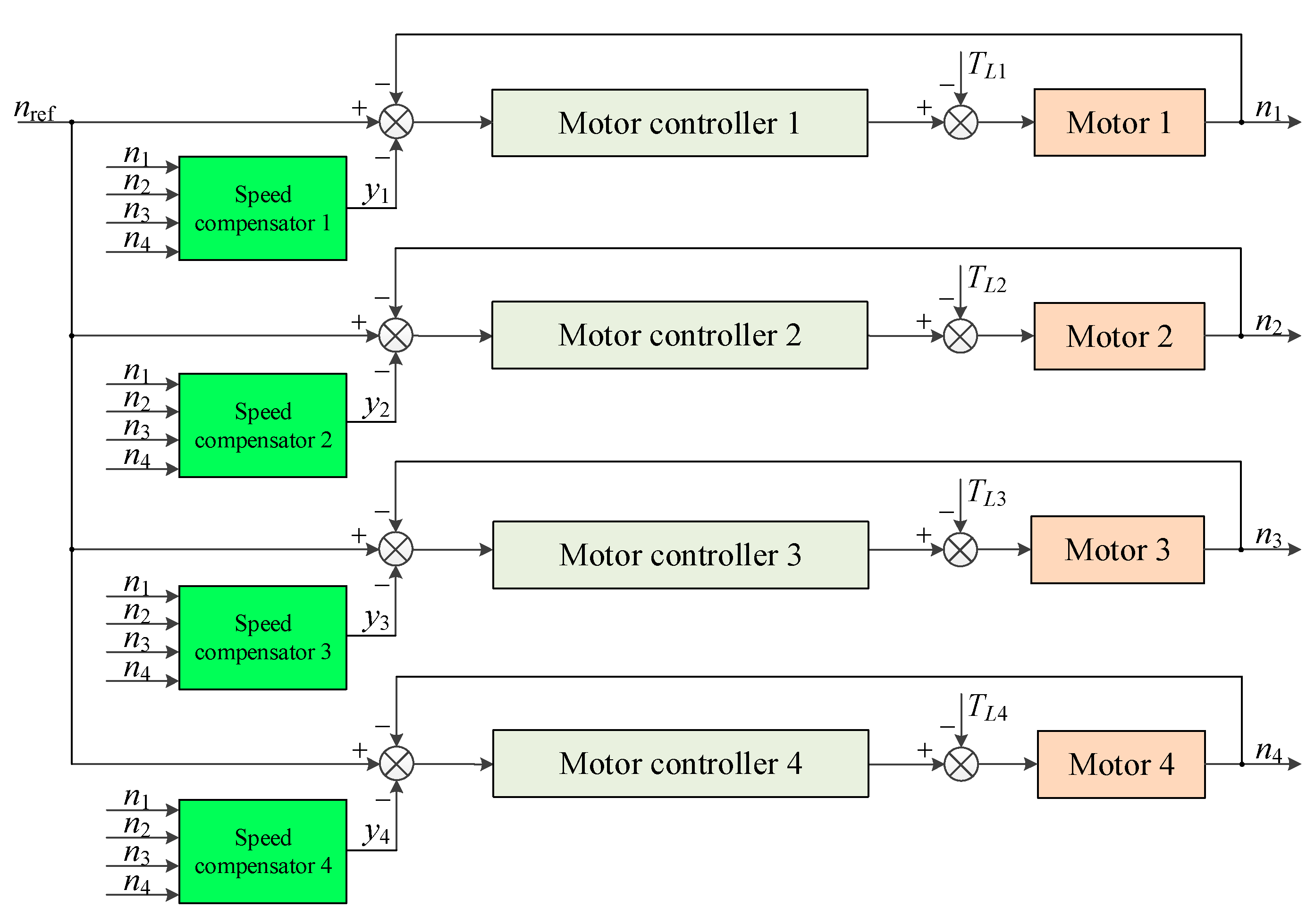
Figure 3.
Structure of the speed compensator.

Figure 4.
Structure of the improved speed compensator.
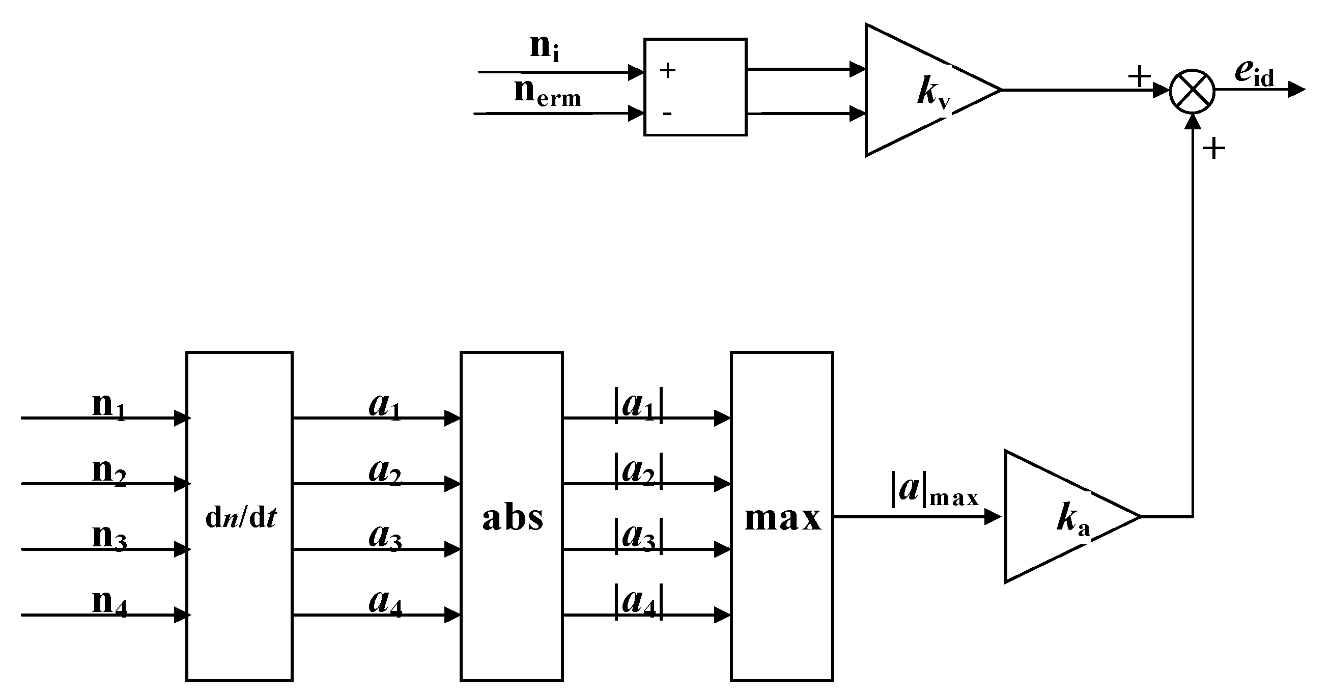
Figure 5.
Block diagram of distributed cooperative control.
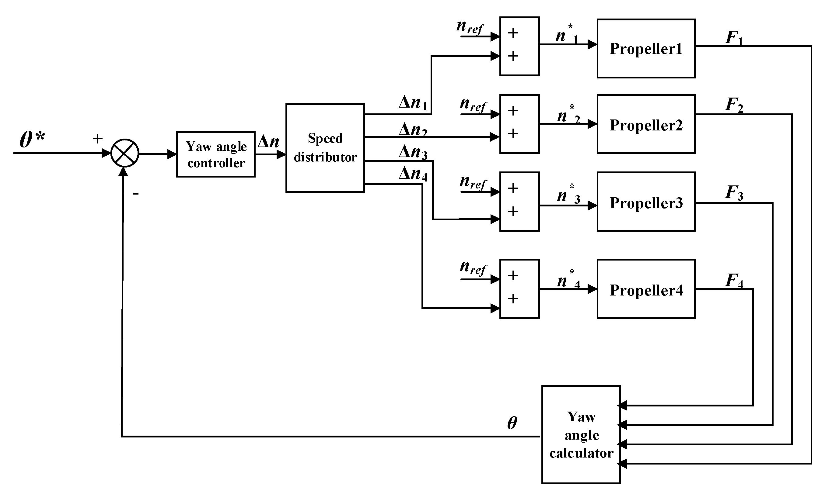
Figure 6.
The schematic diagram of the system.
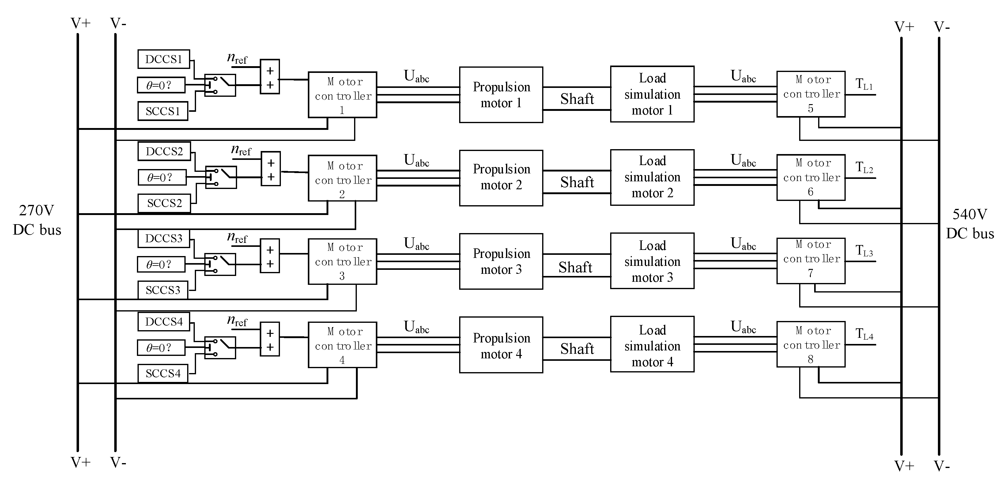
Figure 7.
Speed difference waveform under relative coupling control.
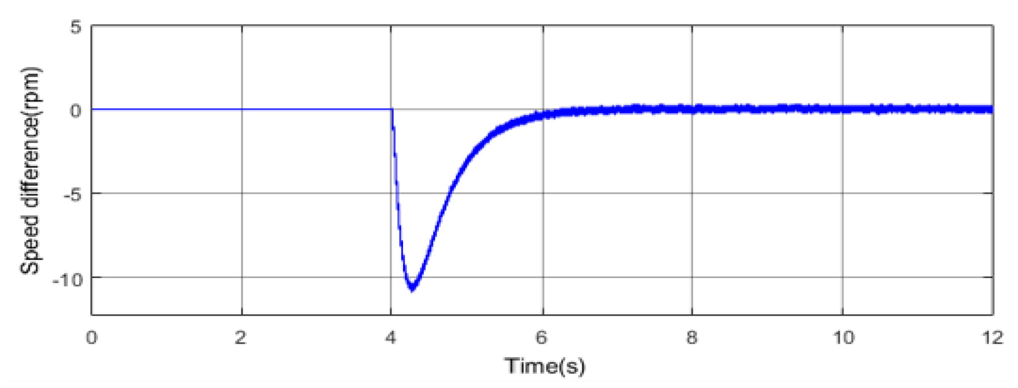
Figure 8.
Speed difference waveform under improved relative coupling control.
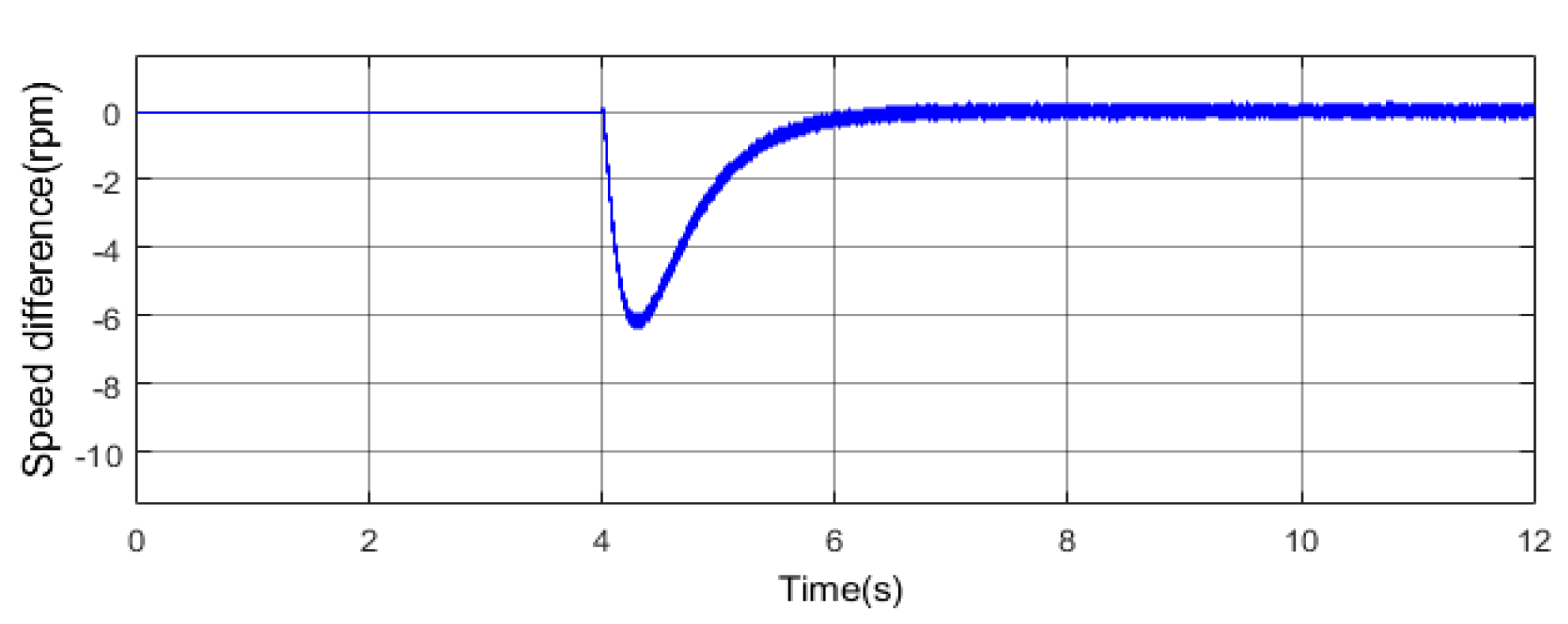
Figure 9.
Waveforms when turning 30 degrees right.


Figure 10.
Waveforms when turning 60 degrees left.

Figure 11.
Experimental platform.

Figure 12.
Speed waveform of each motor under the relative coupling control.
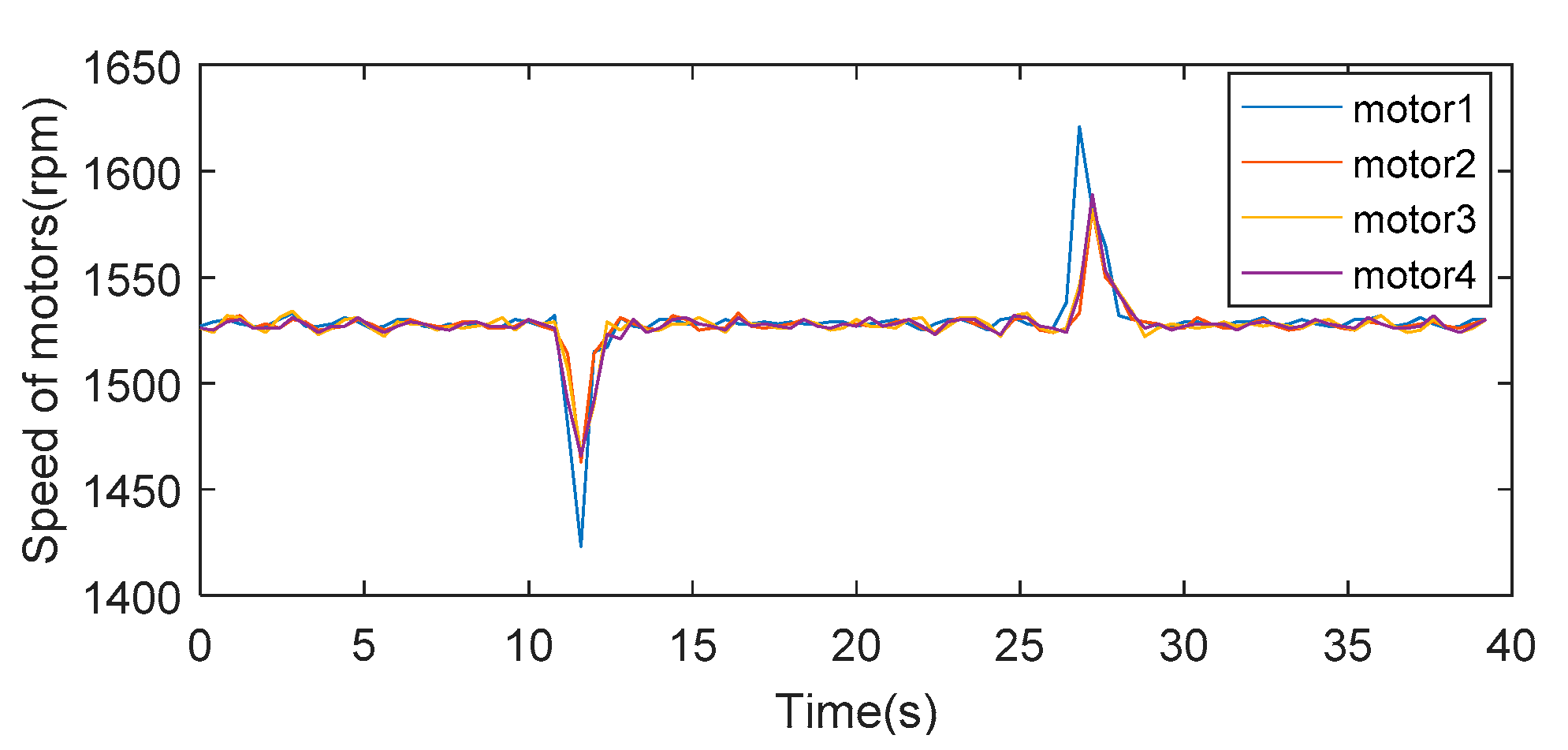
Figure 13.
Speed waveform of each motor under the improved relative coupling control.
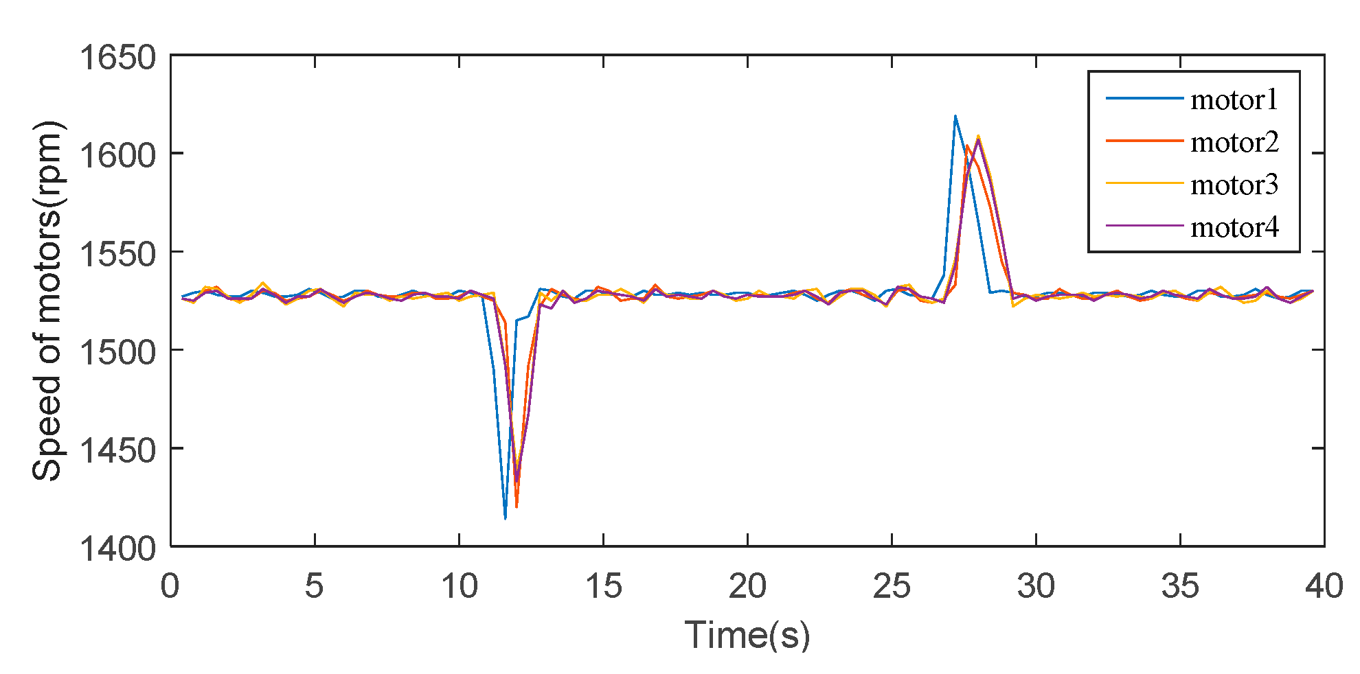
Figure 14.
Load torque waveforms of each motor.

Figure 15.
Experimental waveforms of distributed cooperative control.


Table 1.
Variables and their meanings.
| Variables | Definitions |
|---|---|
| given speed of all motors | |
| actual speed of motor i | |
| given speed after compensation of motor i | |
| Δn | output value of yaw angle controller |
| Δ | compensation speed of motor i output by the speed distributor |
| nerm | maximum speed synchronization error |
| speed compensator output of motor i | |
| improved speed compensator output of motor i | |
| TLi | load torque of motor i |
| acceleration of motor i | |
| λi | speed proportional factor of motor i |
| kij | feedback gain coefficient |
| moment of inertia of motor i | |
| kv | velocity compensation coefficient |
| ka | acceleration compensation coefficient |
| steering angular velocity of the aircraft | |
| steering moment of inertia of the aircraft | |
| M | yaw moment of the aircraft |
| * | given yaw angle |
| actual yaw angle | |
| Fi | thrust output of propeller i |
Table 2.
Key parameters of the simulation model.
| Parameters | Values |
|---|---|
| bus voltage | 270 V |
| rated speed of motors | 2000 rpm |
| rated power of motors | 15 kW |
| flux linkage of permanent magnet | 0.1225 Wb |
| quadrature axis inductance | 0.8 mH |
| direct axis inductance | 0.8 mH |
| moment of inertia of propulsion motors | 0.008 kg∙m2 |
Publisher’s Note: MDPI stays neutral with regard to jurisdictional claims in published maps and institutional affiliations. |
© 2021 by the authors. Licensee MDPI, Basel, Switzerland. This article is an open access article distributed under the terms and conditions of the Creative Commons Attribution (CC BY) license (https://creativecommons.org/licenses/by/4.0/).
Share and Cite
MDPI and ACS Style
Weng, L.; Zhang, X.; Yao, T.; Bu, F.; Li, H. A Thrust Cooperative Control Strategy of Multiple Propulsion Motors for Distributed Electric Propulsion Aircraft. World Electr. Veh. J. 2021, 12, 199. https://doi.org/10.3390/wevj12040199
AMA Style
Weng L, Zhang X, Yao T, Bu F, Li H. A Thrust Cooperative Control Strategy of Multiple Propulsion Motors for Distributed Electric Propulsion Aircraft. World Electric Vehicle Journal. 2021; 12(4):199. https://doi.org/10.3390/wevj12040199
Chicago/Turabian StyleWeng, Luhui, Xuan Zhang, Taike Yao, Feifei Bu, and Hang Li. 2021. "A Thrust Cooperative Control Strategy of Multiple Propulsion Motors for Distributed Electric Propulsion Aircraft" World Electric Vehicle Journal 12, no. 4: 199. https://doi.org/10.3390/wevj12040199