Article

A Reference Voltage Self-Correction Method for Capacitor Voltage Offset Suppression of Three-Phase Four-Switch Inverter-Fed PMSM Drives

School of Electrical Engineering, Tiangong University, Tianjin 300387, China
*
Author to whom correspondence should be addressed.
World Electr. Veh. J. 2022, 13(2), 24; https://doi.org/10.3390/wevj13020024
Submission received: 25 December 2021 / Revised: 15 January 2022 / Accepted: 17 January 2022 / Published: 19 January 2022

Abstract

:
This paper proposes a capacitor voltage offset suppression method based on reference voltage self-correction for a three-phase four-switch (TPFS) inverter-fed permanent magnet synchronous motor (PMSM) drive system to improve the motor control performance. Firstly, the αβ-axis reference voltage deviation caused by capacitor voltage offset is analyzed, and the relationship between the voltage to be compensated and the offset is obtained. Then, the capacitor voltage offset is calculated according to the motor speed, rotor position, current vector amplitude, and capacitance on the capacitor bridge arm of the TPFS inverter. Finally, the reference voltage is corrected according to the voltage to be compensated and the capacitor voltage offset. This method is simple and easy to implement, and there is no need to add voltage sensors or filters in the system to extract the capacitor voltage offset, and there is no complex parameter adjustment. The effectiveness of the proposed method is verified by experiments on a 20 kW interior permanent magnet synchronous motor.

1. Introduction

Permanent magnet synchronous motors (PMSMs) are widely used in industry because of their high power density and reliable performance [1,2,3]. Due to the less power switching devices, the three-phase four-switch (TPFS) inverter has become an alternative to the conventional three-phase six-switch (TPSS) inverter in cost-sensitive or fault-tolerant PMSM applications [4,5,6]. Therefore, the TPFS inverter-fed PMSM drive system has received considerable attention in recent decades.
In contrast to the TPSS inverter, the power switch devices in one of the phase bridge arms of the TPFS inverter are replaced by two series capacitors, which are connected to the motor phase winding at the midpoint of the bridge arm. Due to this particular topology, the phase current charges and discharges the capacitor, causing the voltage across the capacitor to vary [7]. The resulting capacitor voltage offset causes the basic voltage vector of the TPFS inverter to offset, affecting the control performance of the drive system [8].
To improve the control performance of TPFS inverter-fed PMSM drive systems, a number of capacitor voltage offset suppression strategies have been proposed. To ensure stable operation of the system, the model predictive control with a capacitor voltage balance control term in the cost function is proposed in [9]. However, this method increases the difficulty of adjusting the system weighting factor. To simplify the calculation, a model predictive control method with a fixed weighting factor to suppress capacitor voltage offset is proposed in [10] by establishing a prediction model for capacitor voltage difference based on the relationship between capacitor voltage and phase current. A simplified model predictive flux control considering capacitor voltage offset suppression is proposed in [11], which only treats flux as the only control term in the cost function and avoids complex weighting factor adjustment. Model predictive control can improve control performance by adding a capacitor voltage offset suppression term to the cost function, but it is inherently computationally intensive and has a large current ripple.
To reduce the computational effort of TPFS inverter-fed PMSM drive systems and to reduce the current ripple, the capacitor voltage offset suppression methods based on vector control are proposed in [12,13,14,15]. The capacitor voltage offset is eliminated by introducing a DC component compensation to the midpoint of the capacitor bank in [12], but the method introduces a second-order low-pass filter to extract the capacitor voltage deviation, which limits the dynamic and steady-state performance of the control system. An adaptive trap filter instead of a second-order low-pass filter in [13], combined with an adaptive control algorithm to suppress capacitor voltage offset and improve the dynamic and steady-state performance of the system. A capacitor voltage balancing method without a filter is proposed in [14], revealing the relationship between capacitor voltage bias and load current through coordinate transformation and then injecting the required compensation current into the stator current control loop. Although this method avoids the use of filters, the system adds a proportional–integral (PI) controller and requires the adjustment of parameters. In [15], the authors propose to directly measure the capacitor voltage using voltage sensors and then compensate the reference voltage using the difference between the capacitor voltage. This method requires no filter and no complex parameter adjustment and is easier to implement than the above methods. Although the control strategy is continuously simplified, voltage sensors are inevitably used, which increases the cost and the size of the system.
A capacitor voltage offset suppression method based on αβ-axis reference voltage self-correction is proposed in this paper. The method calculates the capacitor voltage using the three-phase current, the angular velocity, and the rotor position angle, and then the capacitor voltage offset is obtained by the difference of the capacitor voltage. The αβ-axis reference voltage is corrected by capacitor voltage offset, which does not need to add voltage sensors or filters in the control system to extract the voltage variation components, and there is no complex parameter adjustment. The corrected reference voltage ensures that the basic voltage vector is balanced, and then, the reference voltage vector is synthesized to output the correct PWM pulse signal, which, in turn, modulates the correct three-phase winding voltage, giving the motor good control performance.

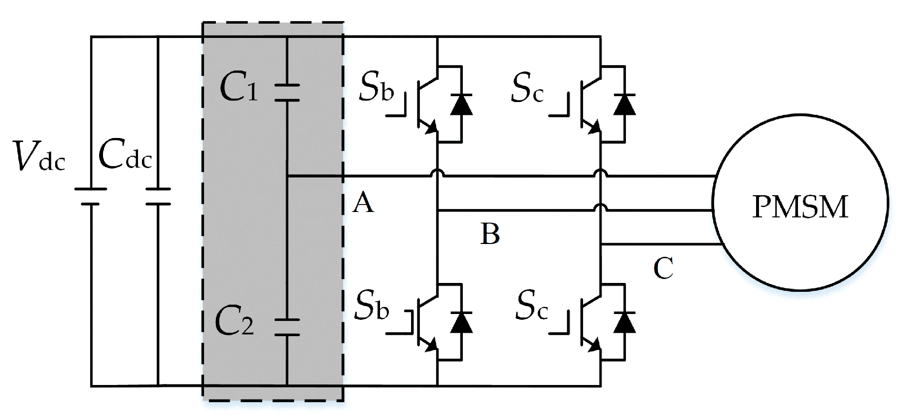
2. Modeling for the TPFS Inverter-Fed PMSM Drive System

The topology of the TPFS inverter-fed PMSM drive system is shown in Figure 1. The system consists of an input DC source, a DC-link capacitor, a one-phase capacitor bridge arm, a two-phase controllable power switch devices bridge arm, and a PMSM. In this paper, the phase A motor is studied as an example connected to the midpoint of the capacitor bridge arm.
In this figure, the shaded part is the capacitor bridge arm formed by the capacitor instead of the controllable power switch devices, Vdc is the system input DC source, Cdc is the DC-link capacitor, C1 and C2 are the two capacitors on the capacitor bridge arm, whose capacitor value is C1 = C2 = C, and Sb and Sc indicate the controllable power switch devices on the bridge arm of B and C phases.
In the synchronous frame, the voltage equation of a PMSM can be expressed as
[ u d u q ] = [ R s + p L d ω e L q ω e L d R s + p L q ] [ i d i q ] + [ 0 ω e φ f ]
where ud and uq are the stator voltage components of the motor in the d–q frame; id and iq are currents in the d–q frame; Rs is the stator resistance; Ld and Lq are the d-axis stator inductance and q-axis stator inductance; ωe is the electrical angular velocity; φf is the stator flux linkage of the permanent magnet; p is the difference operator.
In Equation (1) id and iq are the projections of the PMSM stator current vector Is on the d–q axis, respectively, which can be expressed as
{ i d = I s sin β i q = I s cos β
where Is is the stator current vector amplitude, and β is the angle between the current vector and the q-axis.
A common control strategy for PMSM is the maximum torque per ampere (MTPA) control strategy. For the interior PMSM, the current vector angle at the MTPA operating point can be expressed as
β M = sin 1 ( φ f + λ f 2 + 8 ( L d L q ) 2 I s 2 4 ( L d L q ) I s )
where βM is the current vector angle at the MTPA operating point; according to the literature [16], this angle varies between 0 and 0.25π.
Assuming that the voltages across capacitors C1 and C2 are Vdc1 and Vdc2, respectively, the voltages uAN, uBN, and uCN at the three-phase winding endpoints A, B, and C of the motor relative to the motor midpoint N at different switching states of the TPFS inverter are
{ u AN = V dc 1 3 ( S b S c ) + V dc 2 3 ( S b S c + 2 ) u BN = V dc 1 3 ( 2 S b S c ) + V dc 2 3 ( 2 S b S c 1 ) u CN = V dc 1 3 ( S b + 2 S c ) + V dc 2 3 ( S b + 2 S c 1 )
where Sb and Sc are the switching states of the B and C phase bridge arms, respectively. When Sb and Sc are 0, it means the state in which the upper switch of the B and C phase bridge arm is not conducting, and the lower switch is conducting; when Sb and Sc are 1, it means the state in which the upper switch of the B and C phase bridge arm is conducting, and the lower switch is not conducting. According to the states of the power switch devices, there are four switching states of the TPFS inverter—namely, S00, S10, S11, and S01.

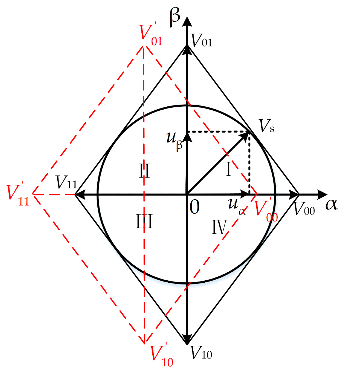
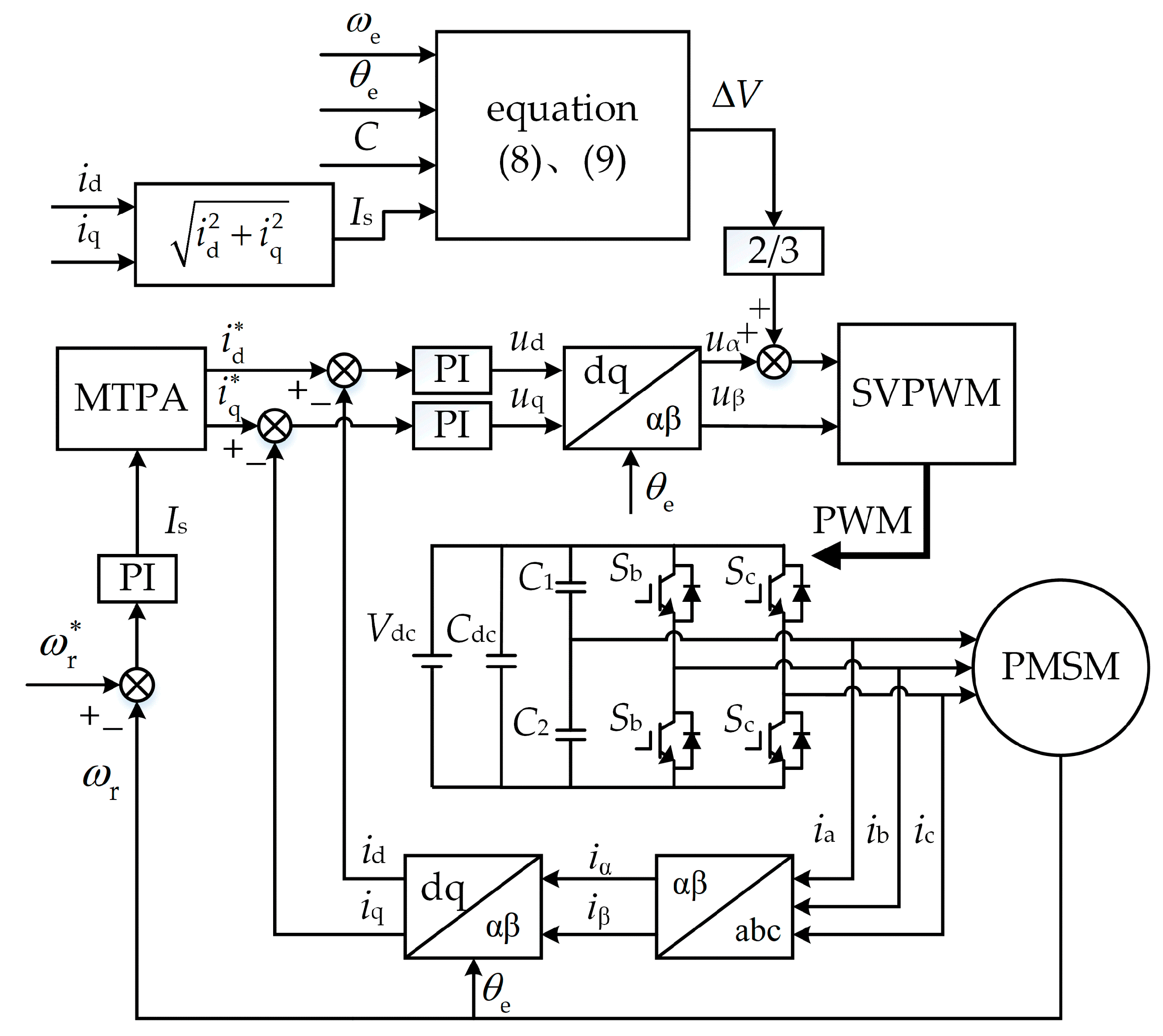
3. Capacitor Voltage Offset Suppression Strategy

3.1. The Influence of TPFS Inverter Capacitor Voltage Offset

Assuming that ΔV is the voltage offset across the capacitors of the TPFS inverter, the voltages across capacitors C1 and C2 are Vdc1 = Vdc/2 + ΔV and Vdc2 = Vdc/2 − ΔV, respectively. Substituting Vdc1 and Vdc2 into Equation (4), we can obtain the relationship between the three-phase winding voltage and the switching state when the capacitor voltage is unbalanced as
{ u AN = V dc 3 ( S b S c + 1 ) 2 Δ V 3 u BN = V dc 3 ( 2 S b S c 1 2 ) + Δ V 3 u CN = V dc 3 ( 2 S c S b 1 2 ) + Δ V 3
The TPFS inverter capacitor voltage offset leads to different offsets in the PMSM three-phase winding voltage. After the Clark variation, one can obtain the voltages in the αβ-axis two-phase stationary coordinate system as
{ u α = V dc 3 ( S b S c + 1 ) 2 Δ V 3 u β = V dc 3 ( 3 S b 3 S c )
As can be seen from Equation (6), although the capacitor voltage offset causes an offset in all three-phase winding voltages, only the α-axis reference voltage uα is offset by −2ΔV/3 after the Clark transformation, while the β-axis reference voltage uβ is not offset.
The space vector pulse width modulation (SVPWM) of the TPFS inverter is an important part to realize vector control of the drive system, where uα and uβ, as αβ-axis reference voltages, determine whether the correct PWM pulse signal can be output. According to Equation (5), the reference voltage uα is offset due to the capacitor voltage offset, which causes the basic voltage vector of the TPFS inverter to shift along the α-axis. The reference voltages uα and uβ that generate the offset cannot be synthesized into the correct reference voltage vector according to the SVPWM strategy of the TPFS inverter. The wrong PWM pulse signal will affect the control performance of the motor.
The four switching states of the TPFS inverter correspond to four basic voltage vectors, V00, V10, V11, and V01. With the capacitor voltage offset taken into account, the distribution of the basic voltage vectors of the TPFS inverter is shown in Figure 2.
In the figure, the red dashed line shows the distribution of the basic voltage vector when the capacitor voltage is offset, and the black shows the distribution of the basic voltage vector when the capacitor voltage is balanced. The α-axis coordinates of the basic voltage vector are shifted, compared with the capacitor voltage balance. The synthesis of the reference voltage vector Vs in this state inevitably leads to an asymmetry of the three-phase voltages. The three-phase voltage asymmetry will inevitably lead to an asymmetry in the three-phase current, which affects the control performance of the motor.

3.2. The TPFS Inverter Capacitor Voltage Offset

According to Figure 1, the motor’s phase A winding is connected to the midpoint of the capacitor bridge arm, and the current in this phase winding charges and discharges the capacitor, causing a voltage offset across the capacitor. The capacitor voltage offset can be expressed as
Δ V = I s j 2 ω e C
It can be seen from Equation (7) that the TPFS inverter capacitor voltage offset is directly proportional to the current vector amplitude and inversely proportional to the motor speed and capacitance, which explains the poor low-speed characteristics of the TPFS inverter drive system.
To improve motor control performance, the capacitor value on the capacitor bridge arm of the TPFS inverter can be increased, or the motor speed can be increased. However, the capacitor value cannot be increased indefinitely, and the motor inevitably runs at low speed in the TPFS inverter-fed PMSM drive systems. The use of a TPFS inverter capacitor voltage offset suppression strategy is, therefore, of great importance for TPFS inverter-fed PMSM drive systems.

3.3. Reference Voltage Self-Correction

According to the analysis in 3.1, the TPFS inverter capacitor voltage offset causes a −2ΔV/3 offset in the reference voltage uα. Therefore, the correct PWM pulse signal can be guaranteed to be output by correcting the α-axis reference voltage to give good control performance of the motor.
As the motor phase winding load current varies sinusoidally, the charging and discharging of the capacitors results in the voltages Vdc1 and Vdc2 across the capacitors varying with the motor rotation as follows:
{ V dc 1 = V dc 2 + I s 2 ω e C cos ( ω e t ) + Δ V dc V dc 2 = V dc 2 I s 2 ω e C cos ( ω e t ) Δ V dc
where ωe is the angular velocity of the motor, and ωet is the rotor position angle of the motor. ΔVdc represents the DC voltage offset across the capacitors of the three-phase four-switch inverter, which is negligible, due to the equal capacitance of the two capacitors on the bridge arm of the selected capacitor in the TPFS inverter. Therefore, the voltage offset across the capacitors can be expressed as
Δ V = 1 2 ( V dc 1 V dc 2 ) = I s 2 ω e C cos ( ω e t )
According to Equation (9), the capacitor voltage offset can be calculated based on the angular velocity of the motor, rotor position angle of the motor, capacitor value, and current vector amplitude, without the need for additional voltage sensors or filters in the TPFS inverter-fed PMSM drive system.
From Equation (6), it can be seen that the reference voltage uα generates an offset of −2ΔV/3 and the reference voltage uβ remains unchanged, so only 2ΔV/3 needs to be compensated on the reference voltage uα to obtain the corrected α-axis reference voltage. The corrected αβ-axis reference voltage expresses as
{ u α = u α + 2 Δ V 3 u β = u β
By using the corrected αβ-axis reference voltage for the TPFS inverter using a space vector pulse width modulation strategy, the correct PWM pulse signal can be generated to output an offset-free reference voltage vector, modulating a symmetrical three-phase winding voltage and controlling the PMSM to achieve good performance.
The block diagram of the TPFS inverter-fed PMSM vector control considering the capacitor voltage offset suppression strategy proposed in this paper is shown in Figure 3.

4. Simulation and Experimental Results

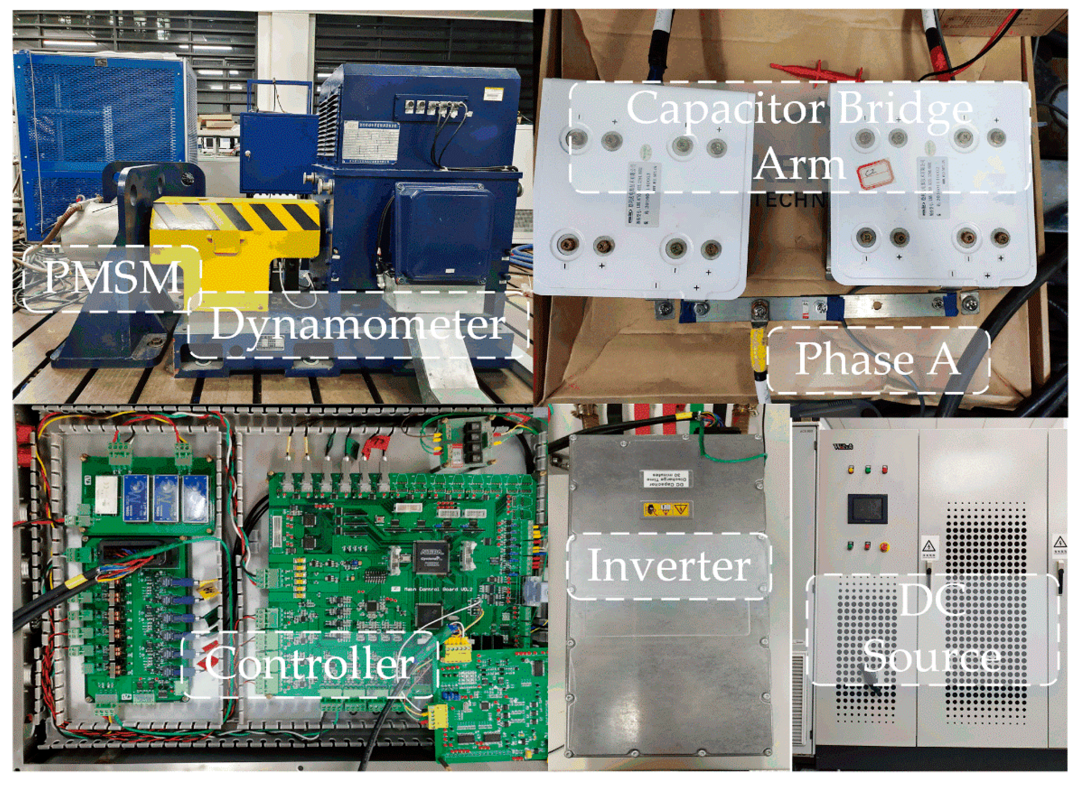
4.1. Introduction to the Experimental Platform

In order to verify the effectiveness of the capacitor voltage offset suppression strategy proposed in this paper, experimental verification was carried out on a 20 kW interior PMSM. The experimental platform of the TPFS inverter-fed PMSM drive system shown in Figure 4 was built.
The experimental platform consists of a dynamometer, a DC power supply, an inverter, a capacitor bridge arm, a controller, and a PMSM. The dynamometer is an induction motor that provides the load torque for the experimental prototype. The digital signal processing chip for the controller was TMS320F28335, and the inverter was an electric vehicle GD12-WDI power unit manufactured by Semikron. The motor’s A-phase line was connected to the neutral point of the capacitor bank, to form the A-phase capacitor bridge arm, which formed the TPFS inverter with the bridge arms of B- and C-phase-controlled power switch devices of the Semikron inverter. The control frequency is 10 kHz, and the DC bus voltage is 320 V.
The experimental prototype parameters are shown in Table 1.

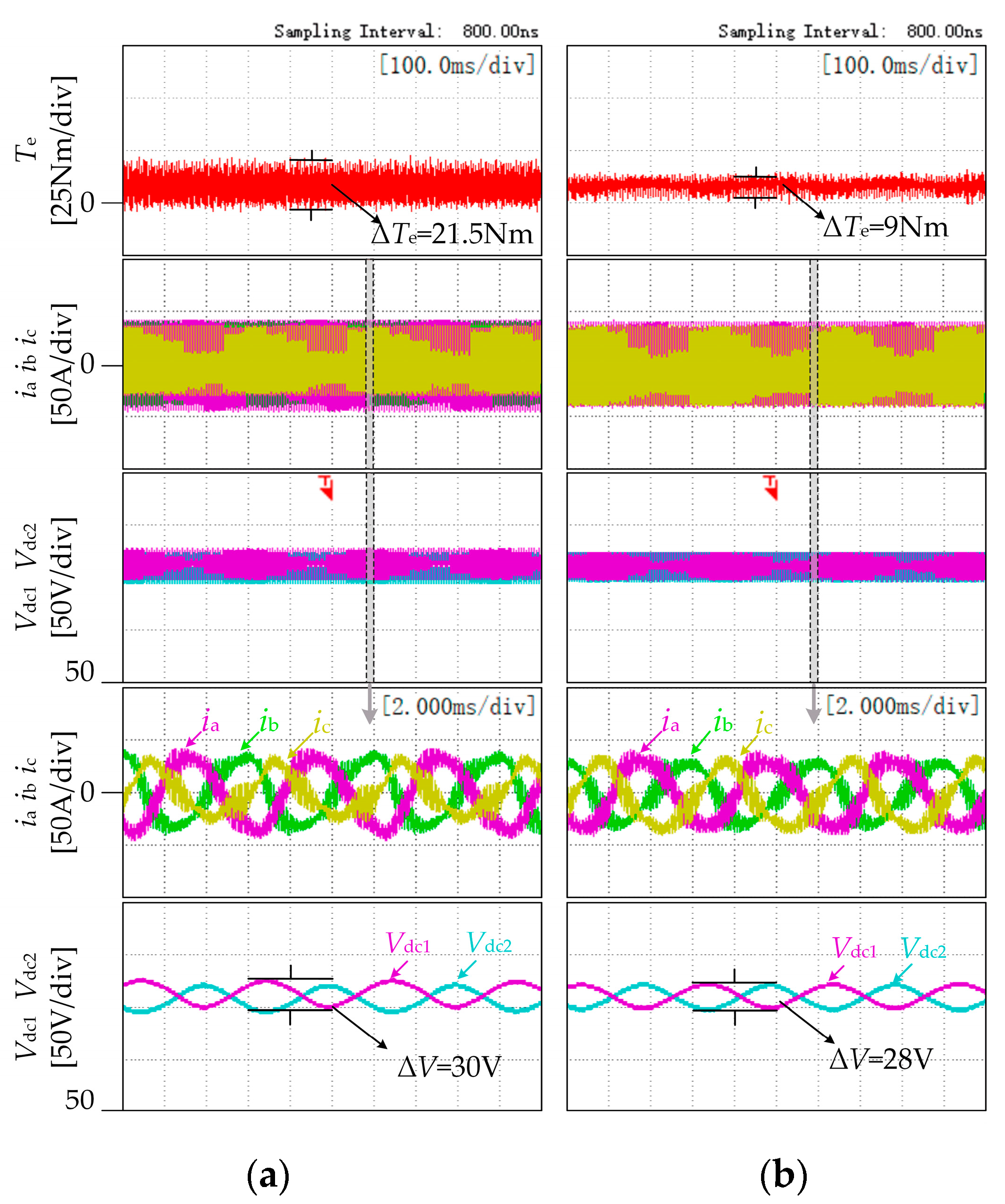
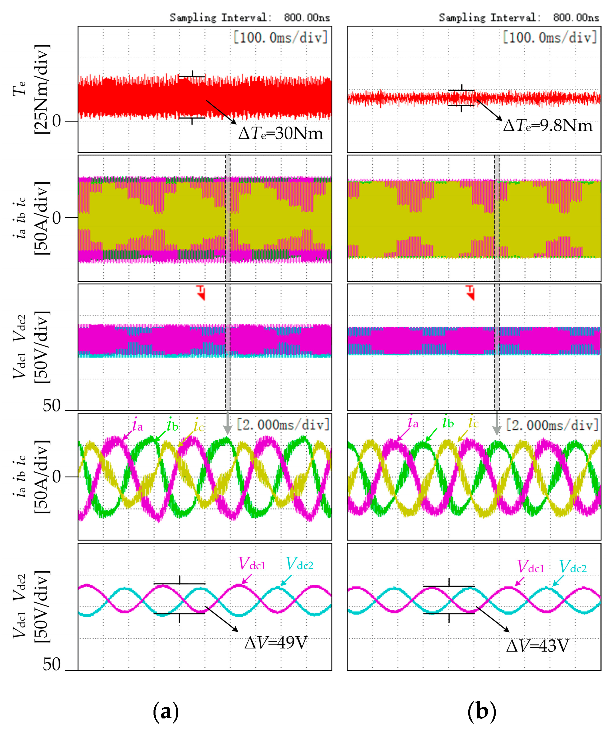
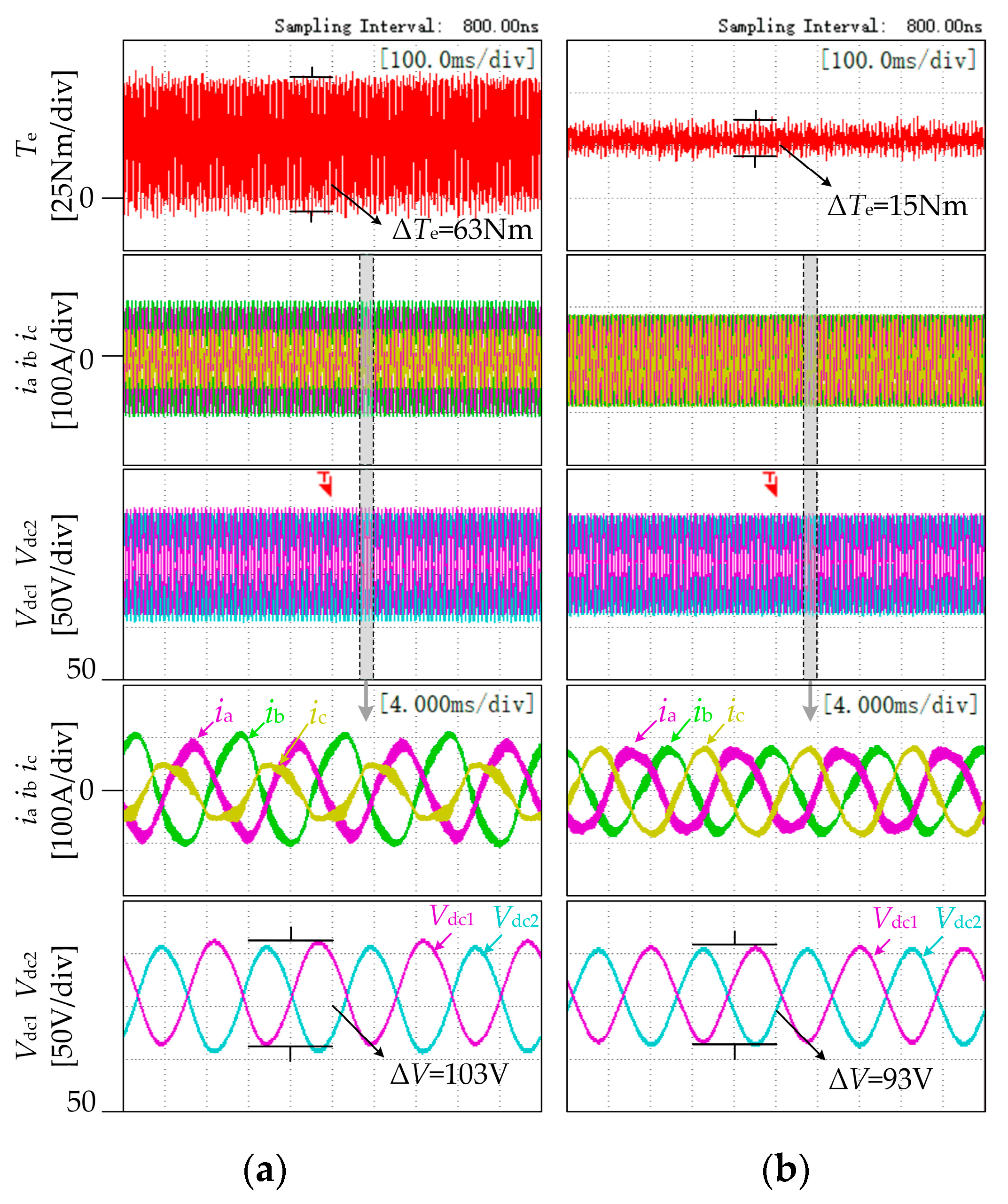
4.2. Experimental Results for Comparision of Control Performance

In the experiments, the capacitor voltage offset suppression strategy proposed in this paper was applied to the TPFS inverter-fed PMSM drive system, and the experimental results were compared with those without any capacitor voltage offset suppression. The effectiveness of the proposed method was verified in terms of torque ripple of the motor, three-phase current of the motor, and capacitor voltage offset of the TPFS inverter.
Figure 5 shows the experimental waveforms at the speed 2500 r/min and the load 10 Nm. From the top to the bottom is the motor torque Te, three-phase current ia ib, ic, capacitor voltage Vdc1 and Vdc2, the amplification waveforms of three-phase current, and the amplification waveforms of capacitor voltage are shown, respectively. Figure 5a shows the experimental waveforms without capacitor voltage offset suppression. The waveforms show that the torque ripple reaches 21.5 Nm, and the three-phase current and the capacitor voltage of the TPFS inverter are unbalanced, where the capacitor voltage offset is 30 V. Figure 5b shows the experimental waveforms with the proposed method. Since the proposed method corrects the reference voltage so that the TPFS inverter synthesizes the correct reference voltage vector, the torque ripple of the proposed method is 9 Nm, compared with the experimental waveform without capacitor voltage offset suppression, which effectively reduces the torque ripple caused by the capacitor voltage offset. The three-phase current and the capacitor voltage of the TPFS inverter are balanced by the proposed method, where the capacitor voltage offset is reduced to 28 V, which effectively improves the motor control performance.
Figure 6 shows the experimental waveforms at the speed 2500 r/min and the load 20 Nm, and Figure 7 shows the experimental waveforms at the speed of 2500 r/min and the load of 30 Nm. The waveforms show that the torque ripple is 30 Nm and 45 Nm without capacitor voltage offset suppression, and the three-phase current and the capacitor of the TPFS inverter are significantly unbalanced, where the capacitor voltage offset is 49 V and 65 V. The capacitor voltage offset suppression method proposed in this paper reduces the torque ripple to 9.8 Nm and 15 Nm. The three-phase current and capacitor voltage of the TPFS inverter are balanced, where the capacitor voltage offset is reduced to 43 V and 57 V. Therefore, the proposed method improved the control performance of the motor effectively.
According to Equation (7), the capacitor voltage offset of the TPFS inverter is proportional to the current vector amplitude. Comparing the experimental waveforms in Figure 5, Figure 6 and Figure 7 for the cases without capacitor voltage offset suppression reveals that the torque ripple increases significantly with the increase in load torque, and the three-phase current and capacitor voltage are unbalanced. After applying the proposed method to suppress the capacitor voltage offset of the TPFS inverter, the torque ripple only increases slightly as the load torque increases, while the three-phase current and the capacitor voltage of the TPFS inverter remain in balance. The increase in load has little effect on the control performance of the proposed method in this paper.
To further verify the effectiveness of the proposed method, experiments were carried out at the speed of 1500 r/min with loads of 10 Nm, 20 Nm, and 30 Nm. The experimental waveforms are shown in Figure 8, Figure 9 and Figure 10. According to Figure 8a, Figure 9a and Figure 10a, the torque ripple without capacitor voltage offset suppression is 26.5 Nm, 43 Nm, and 63 Nm, respectively. The three-phase current and the capacitor voltage of the TPFS inverter are unbalanced; the capacitor voltage offset is 45 V, 73.5 V, and 103 V, and the control performance of the motor is poor. The experimental waveforms with the proposed method are shown in Figure 8a, Figure 9a and Figure 10a, and the torque ripple with the proposed method is 10 Nm, 11.5 Nm, and 15 Nm, respectively, which effectively reduces the torque ripple, compared with the method without capacitor voltage offset suppression. The three-phase current and the capacitor voltage of the TPFS inverter are balanced, and the capacitor voltage offset is reduced to 42 V, 65 V, and 93 V. The method proposed in this paper improves the control performance of the motor. Moreover, as the load torque increases, the torque ripple of the proposed method only increases slightly. However, the torque ripple increases greatly as the load increases without capacitor voltage offset suppression.
According to Equation (7), the capacitor voltage offset is inversely proportional to the motor speed. Comparing the experimental waveforms in Figure 5 and Figure 8, Figure 6 and Figure 9, and Figure 7 and Figure 10 reveals that the torque ripple increases considerably as the speed decreases with the same load torque, and the unbalanced phenomenon of the three-phase current and the capacitor voltage of the TPFS inverter is aggravated. The torque ripple only increases slightly as the motor speed decreases with the proposed method, and the three-phase current and the voltage across the capacitor remain in balance. The speed reduction has little effect on the control performance of the proposed method.
The above experimental waveforms show that the torque ripple and the capacitor voltage offset are reduced effectively with the method proposed in this paper while keeping the three-phase current and the capacitor voltage in balance. The proposed method improves the control performance of the motor. At the same time, it does not deteriorate the control performance as the motor load torque increases and the speed decreases.

4.3. Simulation Results of the Capacitor Value Variation

Figure 11 shows the simulation results of the proposed method when the motor running at 2500 r/min and 30 Nm operating conditions. In Figure 11, ia ib, ic is the three-phase current, and Te is the motor torque. Figure 11a–c are the simulation results for capacitor values of 2000 μF, 1500 μF, and 1000 μF, respectively. It can be seen from the simulation results that the method proposed in this paper still maintains the three-phase current balanced, and torque ripple is almost constant when the capacitor value variations.

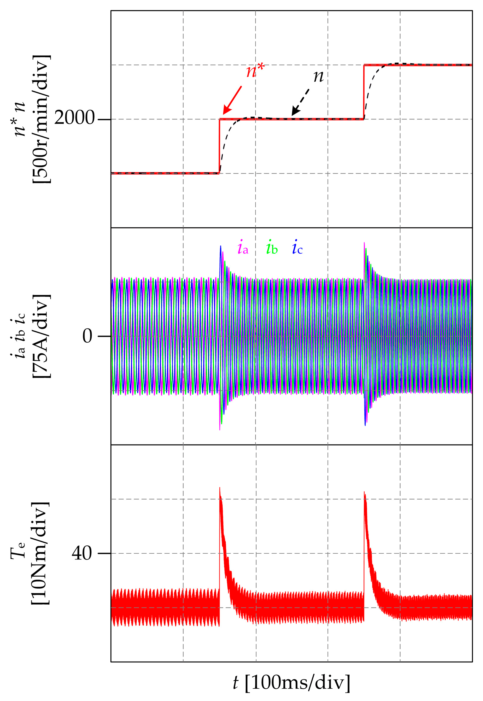
4.4. Simulation Results of Speed Transient

Figure 12 shows the simulation results of the proposed method during the motor speed step change with 500 r/min from 1500 r/min to 2500 r/min. In Figure 12, n* and n indicate the given motor reference speed and the actual motor speed, respectively; ia, ib, ic is the three-phase current, and Te is the motor torque. It can be seen from the simulation results that the motor will generate current and torque strikes but will soon return to normal when the motor speed is transient, and the motor actual speed can quickly track the reference speed. After the motor speed is stabilized, the three-phase current returns to balance, and the torque ripple returns to normal.

5. Conclusions

This paper proposed a voltage sensorless TPFS inverter-fed PMSM capacitor voltage offset suppression strategy that enables the TPFS inverter to synthesize the correct reference voltage vector by correcting the αβ-axis reference voltage. The effectiveness of the proposed method was verified experimentally, and the method has the following characteristics:
(1).
The proposed method effectively reduces the torque ripple while keeping the three-phase current and capacitor voltage in balance. Load increase and speed decrease have little effect on the proposed method;
(2).
The proposed method does not need voltage sensors or filters to extract the offset components, nor does it require complex parameter adjustment, as the algorithm is simple and easy to implement;
(3).
The proposed method will not affect the control performance of the motor when the capacitor value variation and the motor speed are transient.

Author Contributions

Conceptualization, W.C. and X.L.; data curation, G.Z.; Funding acquisition, W.C. and X.L.; methodology, W.C. and S.W.; project administration, W.C.; supervision, X.L.; visualization, S.W.; writing—original draft preparation, S.W.; writing—review and editing, S.W. All authors will be informed about each step of manuscript processing including submission, revision, revision reminder, etc. via emails from our system or assigned Assistant Editor. All authors have read and agreed to the published version of the manuscript.

Funding

This research was funded by The National Natural Science Foundation of China, Grant Numbers 51807141 and 52077156, and The Key Program of Tianjin Natural Science Foundation, Grant Number 20JCZDJC00020.

Institutional Review Board Statement

Not applicable.

Informed Consent Statement

Not applicable.

Conflicts of Interest

The authors declare no conflict of interest.

References

  1. Zhu, Y.; Tao, B.; Xiao, M.; Yang, G.; Zhang, X.; Lu, K. Luenberger Position Observer Based on Deadbeat-Current Predictive Control for Sensorless PMSM. Electronics 2020, 9, 1325. [Google Scholar] [CrossRef]
  2. Lin, Z.; Li, X.; Wang, Z.; Shi, T.; Xia, C. Minimization of additional high-frequency torque ripple for square-wave voltage injection IPMSM sensorless drives. IEEE Trans. Power Electron. 2020, 35, 13345–13355. [Google Scholar] [CrossRef]
  3. Chen, W.; Zeng, S.; Zhang, G.; Shi, T.; Xia, C. A modified double vectors model predictive torque control of permanent magnet synchronous motor. IEEE Trans. Power Electron. 2019, 34, 11419–11428. [Google Scholar] [CrossRef]
  4. Kivanc, O.; Ozturk, S. Low-cost position sensorless speed control of PMSM drive using four-switch inverter. Energies 2019, 12, 741. [Google Scholar] [CrossRef] [Green Version]
  5. Ni, K.; Hu, Y.; Liu, Y.; Gan, C. Performance analysis of a four-switch three-phase grid-side converter with modulation simplification in a doubly-fed induction generator-based wind turbine (DFIG-WT) with different external disturbances. Energies 2017, 10, 706. [Google Scholar] [CrossRef]
  6. Lu, J.; Hu, Y.; Zhang, X.; Wang, Z.; Liu, J.; Gan, C. High-frequency voltage injection sensorless control technique for IPMSMs fed by a three-phase four-switch inverter with a single current sensor. IEEE Trans. Mech. 2018, 23, 758–768. [Google Scholar] [CrossRef]
  7. Zeng, Z.; Zhu, C.; Jin, X.; Shi, W.; Zhao, R. Hybrid space vector modulation strategy for torque ripple minimization in three-phase four-switch inverter-fed PMSM drives. IEEE Trans. Ind. Electron. 2017, 64, 2122–2134. [Google Scholar] [CrossRef]
  8. Zhu, C.; Zeng, Z.; Zhao, R. Comprehensive analysis and reduction of torque ripples in three-phase four-switch inverter-fed PMSM drives using space vector pulse-width modulation. IEEE Trans. Power Electron. 2017, 32, 5411–5424. [Google Scholar] [CrossRef]
  9. Zhou, D.; Zhao, J.; Liu, Y. Predictive torque control scheme for three-phase four-switch inverter-fed induction motor drives with DC-link voltages offset suppression. IEEE Trans. Power Electron. 2015, 30, 3309–3318. [Google Scholar] [CrossRef]
  10. Hang, J.; Zhang, J.; Wu, H.; Ding, S. Model predictive control with fixed weighting factor for three-phase four-switch inverter-fed PMSM drives considering capacitor voltage offset suppression. IET Electric. Power Applica 2020, 14, 2697–2706. [Google Scholar] [CrossRef]
  11. Sun, D.; Su, J.; Sun, C.; Nian, H. A simplified MPFC with capacitor voltage offset suppression for the four-switch three-phase inverter-fed PMSM drive. IEEE Trans. Ind. Electron. 2019, 66, 7633–7642. [Google Scholar] [CrossRef]
  12. Zeng, Z.; Zheng, W.; Zhao, R.; Zhu, C.; Yuan, Q. Modeling, modulation, and control of the three-phase four-switch PWM rectifier under balanced voltage. IEEE Trans. Power Electron. 2016, 31, 4892–4905. [Google Scholar] [CrossRef]
  13. Zhu, C.; Zeng, Z.; Zhao, R. Adaptive suppression method for DC-link voltage offset in three-phase four-switch inverter-fed PMSM drives. Electron. Lett. 2016, 52, 1442–1444. [Google Scholar] [CrossRef]
  14. Yuan, Q.; Zhao, R. DC-link capacitor voltage offset suppression with no filters for three-phase four-switch inverter fed PMSM drives. Electron. Lett. 2017, 53, 751–752. [Google Scholar] [CrossRef]
  15. Kim, B.; Lee, D. Sensorless control of PMSM by a four-switch inverter with compensation of voltage distortion and adjustment of position estimation gain. J. Electr. Eng. Technol. 2017, 12, 100–109. [Google Scholar] [CrossRef] [Green Version]
  16. Bolognani, S.; Petrella, R.; Prearo, A.; Sgarbossa, L. Automatic tracking of MTPA trajectory in IPM motor drives based on AC current injection. IEEE Trans. Ind. Appl. 2011, 47, 105–114. [Google Scholar] [CrossRef]
Figure 1. TPFS inverter-fed PMSM drive system topology.
Wevj 13 00024 g001
Figure 2. Distribution of voltage vectors under capacitor voltage offset.
Wevj 13 00024 g002
Figure 3. The block diagram of TPFS inverter-fed PMSM vector control.
Wevj 13 00024 g003
Figure 4. Experimental platform.
Wevj 13 00024 g004
Figure 5. Experimental results at 2500 r/min and 10 Nm: (a) without capacitor voltage offset suppression; (b) proposed method.
Wevj 13 00024 g005
Figure 6. Experimental results at 2500 r/min and 20 Nm: (a) without capacitor voltage offset suppression; (b) proposed method.
Wevj 13 00024 g006
Figure 7. Experimental results at 2500 r/min and 30 Nm: (a) without capacitor voltage offset suppression; (b) proposed method.
Wevj 13 00024 g007
Figure 8. Experimental results at 1500 r/min and 10 Nm: (a) without capacitor voltage offset suppression; (b) proposed method.
Wevj 13 00024 g008
Figure 9. Experimental results at 1500 r/min and 20 Nm: (a) without capacitor voltage offset suppression; (b) proposed method.
Wevj 13 00024 g009
Figure 10. Experimental results at 1500 r/min and 30 Nm: (a) without capacitor voltage offset suppression; (b) proposed method.
Wevj 13 00024 g010
Figure 11. Simulation results of the capacitor value variation at 2500 r/min and 30 Nm: (a) 2000 μF, (b) 1500 μF, and (c) 1000 μF.
Wevj 13 00024 g011
Figure 12. Simulation results of speed transient.
Wevj 13 00024 g012
Table 1. Experimental prototype parameters.
ParameterSymbolValue
Rated voltage UN320 V
Rated current IN150 A
d-axis inductance Ld0.158 mH
q-axis inductance Lq0.292 mH
Stator resistanceRs7.34 mΩ
Permanent magnet fluxψf0.067 Wb
Rated speednN3000 r/min
Rated torqueTN64 Nm
Pairs of polesp4
Publisher’s Note: MDPI stays neutral with regard to jurisdictional claims in published maps and institutional affiliations.

