
Optimizing Hydro-Pneumatic Inerter Suspension for Improved Ride Comfort and Handling Stability in Engineering Vehicles Using Simulated Annealing Algorithm


Abstract
:1. Introduction
2. Selection of Nonlinear Hydro-Pneumatic Spring
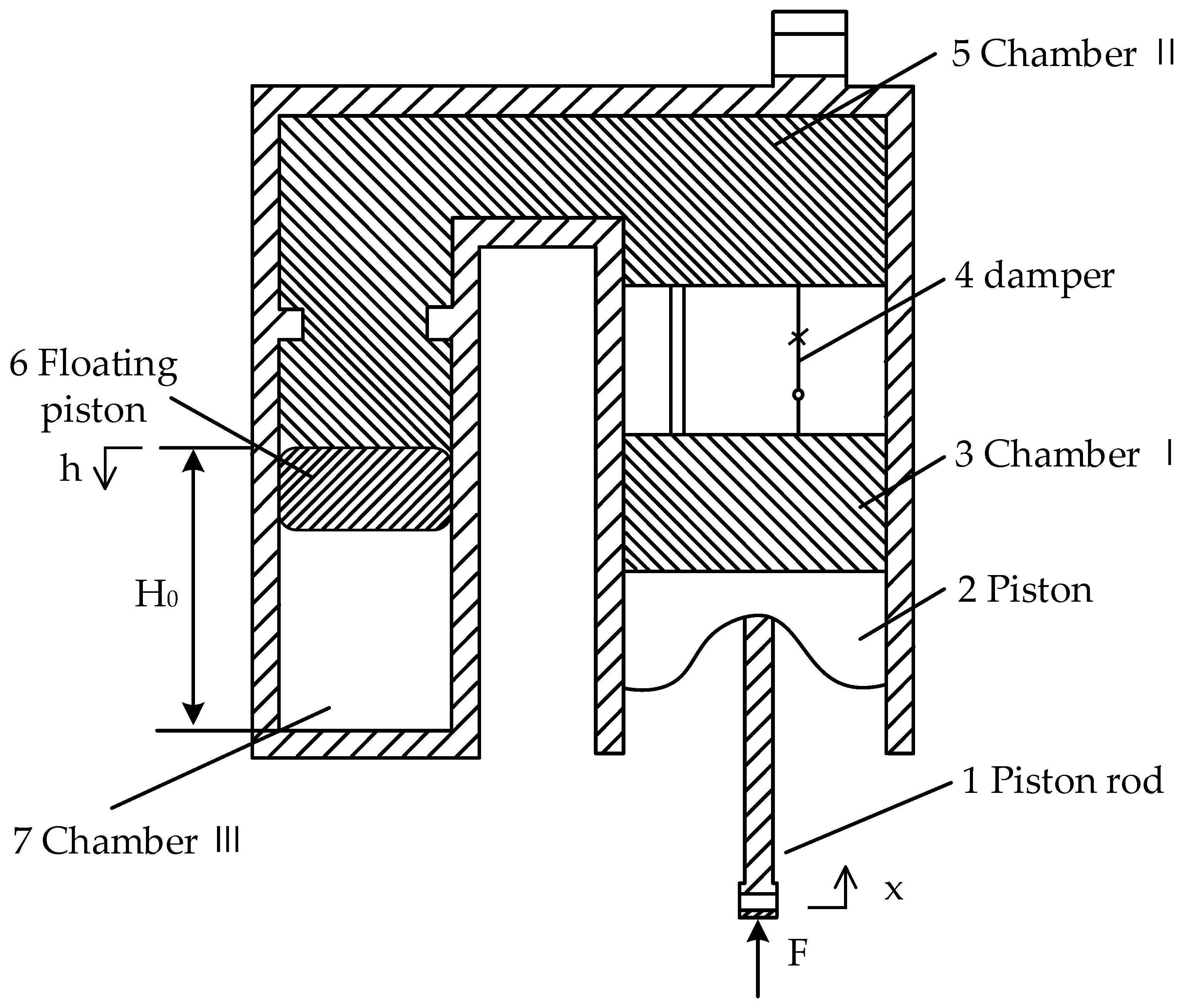
2.1. Working Principle of Hydro-Pneumatic Suspension
2.2. Analysis of Nonlinear Stiffness Characteristics
2.3. Analysis of Nonlinear Damping Characteristics
3. Half-Car Model of HPIS
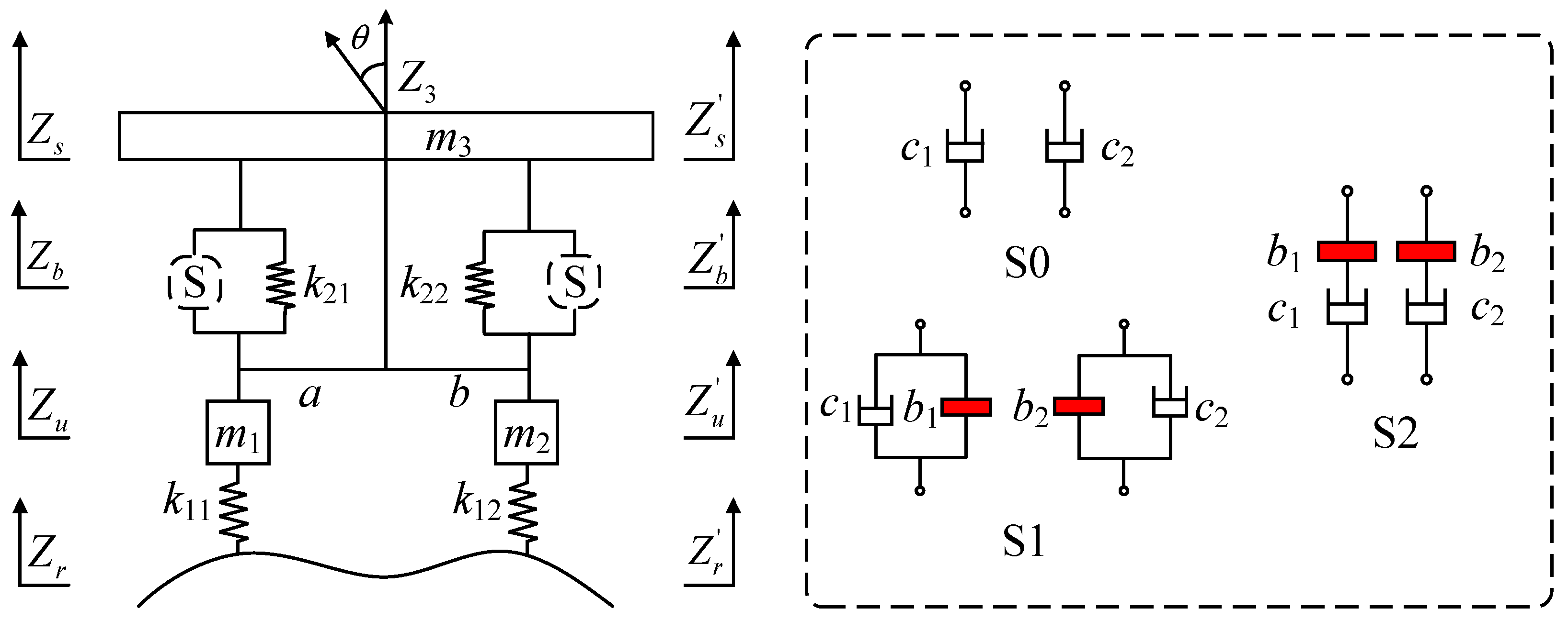
3.1. Half-Car Model
3.2. Selection of Road Excitation
4. Suspension Optimization Analysis
5. Optimization Results
6. Simulation Analysis
7. Conclusions
Author Contributions
Funding
Data Availability Statement
Conflicts of Interest
References
- Yang, W.; Chen, J.; Liu, Z.; Lan, F. Vibration characteristics of framed suv cab based on coupled transfer path analysis. Automot. Innov. 2019, 2, 26–34. [Google Scholar] [CrossRef]
- Yin, C.F.; Zhai, X.H.; Sun, X.Q.; Wang, S.H.; Wong, P.K. Design and performance research of a hydro-pneumatic suspension with variable damping and stiffness characteristics. J. Mech. Sci. Technol. 2022, 36, 4913–4923. [Google Scholar] [CrossRef]
- Zhang, J.W.; Chen, S.Z.; Wu, Z.C.; Yang, L.; Zhang, B. Research on Nonlinear Characteristics of Hydro-Pneumatic Spring and Impact to Ride Performance of Vehicles. In FISITA 2012 World Automotive Congress Proceedings 7: Vehicle Design and Testing. Society of Automotive Engineers of China (SAE-China); Springer: Berlin/Heidelberg, Germany, 2012; p. 12. [Google Scholar]
- Chen, Y.J.; Zhang, Y.F.; Xu, M.Y.; Du, F.; Gui, P. Research on Thermodynamic Modeling and Simulation of Hydro Pneuma-tic Spring. Int. J. Mech. Eng. Robot. Res. 2018, 8, 104–108. [Google Scholar] [CrossRef]
- Ye, Z.; Xie, W.; Yin, Y.; Fu, Z. Dynamic rollover prediction of heavy vehicles considering critical frequency. Automot. Innov. 2020, 3, 158–168. [Google Scholar] [CrossRef]
- Zhang, X.L.; Liu, J.C.; Nie, J.M.; Wei, H.; Chen, L. Simulation Analysis and Experiment Research on Hydro-Pneumatic ISD Suspension. Shock Vib. 2021, 2021, 2095350. [Google Scholar] [CrossRef]
- Yang, L.; Wang, R.; Ding, R.; Liu, W.; Zhu, Z. Investigation on the dynamic performance of a new semi-active hydro-pneumatic inerter-based suspension system with MPC control strategy. Mech. Syst. Signal Process. 2021, 154, 107569. [Google Scholar] [CrossRef]
- Jiao, N.; Guo, J.; Liu, S. Hydro-pneumatic suspension system hybrid reliability modeling considering the temperature influence. IEEE Access 2017, 5, 19144–19153. [Google Scholar] [CrossRef]
- Zhao, Y.; Xu, H.; Deng, Y.; Wang, Q. Multi-objective optimization for ride comfort of hydro-pneumatic suspension vehicles with mechanical elastic wheel. Proc. Inst. Mech. Eng. Part D J. Automob. Eng. 2019, 233, 2714–2728. [Google Scholar] [CrossRef]
- Smith, M.C. Synthesis of mechanical networks: The inerter. IEEE Trans. Autom. Control 2002, 47, 1648–1662. [Google Scholar] [CrossRef]
- Wang, F.C.; Su, W.J. Impact of inerter nonlinearities on vehicle suspension control. Veh. Syst. Dyn. 2008, 46, 575–595. [Google Scholar] [CrossRef]
- Wang, F.C.; Liao, M.K.; Liao, B.H.; Su, W.J.; Chan, H.A. The performance improvements of train suspension systems with mechanical networks employing inerters. Veh. Syst. Dyn. 2009, 47, 805–830. [Google Scholar] [CrossRef]
- Wang, F.C.; Chen, C.W.; Liao, M.K.; Hong, M.F. Performance analyses of building suspension control with inerters. In Proceedings of the 46th IEEE Conference on Decision and Control, New Orleans, LA, USA, 12–14 December 2007; pp. 3786–3791. [Google Scholar]
- Papageorgiou, C.; Smith, M. Laboratory experimental testing of inerters. In Proceedings of the 44th IEEE Conference on Decision and Control, Seville, Spain, 15 December 2005; Institute of Electrical and Electronics Engineers (IEEE): Piscataway, NJ, USA, 2006; pp. 3351–3356. [Google Scholar]
- Shen, Y.J.; Jia, M.Q.; Yang, X.F.; Liu, Y.L.; Chen, L. Vibration suppression using a mechatronic PDD-ISD-combined vehicle suspension system. Int. J. Mech. Sci. 2003, 250, 108277. [Google Scholar] [CrossRef]
- Jiang, J.Z.; Smith, M.C. On the classification of series-parallel electrical and mechanical networks. In Proceedings of the 2010 American Control Conference, Baltimore, MD, USA, 30 June–2 July 2010; Institute of Electrical and Electronics Engineers (IEEE): Piscataway, NJ, USA, 2010; pp. 1416–1421. [Google Scholar]
- Jiang, J.Z.; Smith, M.C. Regular Positive-Real Functions and Five-Element Network Synthesis for Electrical and Mechanical Networks. IEEE Trans. Autom. Control 2011, 56, 1275–1290. [Google Scholar] [CrossRef]
- Shen, Y.; Hua, J.; Fan, W.; Liu, Y.; Yang, X.; Chen, L. Optimal design and dynamic performance analysis of a fractional-order electrical network-based vehicle mechatronic ISD suspension. Mech. Syst. Signal Process. 2023, 184, 109718. [Google Scholar] [CrossRef]
- Baduidana, M.; Kenfack-Jiotsa, A. Optimal design of inerter-based isolators minimizing the compliance and mobility transfer function versus harmonic and random ground acceleration excitation. J. Vib. Control 2021, 27, 1297–1310. [Google Scholar] [CrossRef]
- Papageorgiou, C.; Smith, M. Positive real synthesis using matrix inequalities for mechanical networks: Application to vehicle suspension. IEEE Trans. Control Syst. Technol. 2006, 14, 423–435. [Google Scholar] [CrossRef]
- Wang, F.C.; Yu, C.H.; Chang, M.L.; Hsu, M. The Performance Improvements of Train Suspension Systems with Inerters. In Proceedings of the 45th IEEE Conference on Decision and Control, San Diego, CA, USA, 13–15 December 2006; Institute of Electrical and Electronics Engineers (IEEE): Piscataway, NJ, USA, 2006; pp. 1472–1477. [Google Scholar]
- Nie, J.; Wang, F.; Zhang, X.; Yang, Y. Design and test of hydro-pneumatic ISD suspension in heavy multi-axle vehicles. Adv. Mech. Eng. 2021, 13, 16878140211064737. [Google Scholar] [CrossRef]
- Wang, Y.; Ding, H.; Chen, L. Averaging analysis on a semi-active inerter–based suspension system with relative-acceleration–relative-velocity control. J. Vib. Control 2020, 26, 1199–1215. [Google Scholar] [CrossRef]
- Hu, Y.; Chen, M.Z.; Sun, Y. Comfort-oriented vehicle suspension design with skyhook inerter configuration. J. Sound Vib. 2017, 405, 34–47. [Google Scholar] [CrossRef]
- Liu, C.; Chen, L.; Zhang, X.; Yang, Y.; Nie, J. Design and tests of a controllable inerter with fluid-air mixture condition. IEEE Access 2020, 8, 125620–125629. [Google Scholar] [CrossRef]
- Shen, Y.; Chen, L.; Liu, Y.; Zhang, X. Influence of fluid inerter nonlinearities on vehicle suspension performance. Adv. Mech. Eng. 2017, 9, 168781401773725. [Google Scholar] [CrossRef]
- Zhu, Z.; Wang, R.; Yang, L.; Sun, Z.; Meng, X. Modelling and control of a semi-active dual-chamber hydro-pneumatic inerter-based suspension system. Proc. Inst. Mech. Eng. Part D J. Automob. Eng. 2021, 235, 2355–2370. [Google Scholar] [CrossRef]
- Wang, G.F.; Zhang, Y.X.; Suo, X.F.; Liu, X. Analysis and Simulation of Loading Impact Damping Characteristics for Two-Stage Pressure Hydro-Pneumatic Suspension of a Mining Dump Truck. Eng. Proc. 2022, 24, 2. [Google Scholar] [CrossRef]
- Sun, H.L.; Li, R.C.; Xu, J.K.; Xu, F.N.; Zhang, B.; Dong, X.Y. Fractional Modeling and Characteristic Analysis of Hydro-Pneumatic Suspension for Construction Vehicles. Processes 2021, 9, 1414. [Google Scholar] [CrossRef]
- Choi, K.; Oh, J.S.; Kim, H.S.; Han, H.W.; Park, J.H.; Lee, G.H.; Park, Y.J. Experimental Study on the Dynamic Characteristics of Hydro-Pneumatic Semi-Active Suspensions for Agricultural Tractor Cabins. Appl. Sci. 2020, 10, 8992. [Google Scholar] [CrossRef]
- Sang, Z.; Dong, M.; Gu, L. Numerical analysis of a dual-chamber hydro-pneumatic suspension using nonlinear vibration theory and fractional calculus. Adv. Mech. Eng. 2017, 9, 1687814017705797. [Google Scholar] [CrossRef]
- Darabseh, T.; Al Yafeai, D.; Mourad, A.H.I. Energy harvesting from car suspension system: Mathematical approach for half car model. J. Mech. Eng. Sci. 2021, 15, 7695–7714. [Google Scholar] [CrossRef]
- Yang, X.F.; Yan, L.; Shen, Y.J.; Li, H.C.; Liu, Y.L. Dynamic performance analysis and parameters perturbation study of inerter–spring–damper suspension for heavy vehicle. J. Low Freq. Noise Vib. Act. Control 2021, 40, 1335–1350. [Google Scholar] [CrossRef]
- Prabhahar, M.; Lakshminarayanan, N.; Muhammed, K.A.; Vishnu, M.K.; Varghese, V.J. Design of automobile car seat vibration analysis due to road excitation using CATIA. Mater. Today Proc. 2021, 45, 6287–6291. [Google Scholar] [CrossRef]
- Franco Correia, V.; Moita, J.S.; Moleiro, F.; Soares, C.M.M. Optimization of Metal–Ceramic Functionally Graded Plates Using the Simulated Annealing Algorithm. Appl. Sci. 2021, 11, 729. [Google Scholar] [CrossRef]


| Parameters | Symbolic | Value |
|---|---|---|
| chamber I area (m2) | A1 | 5.8 × 10⁻³ |
| floating piston area (m2) | A2 | 13.2 × 10⁻³ |
| converted height of gas at static equilibrium (m) | H0 | 0.237 |
| density of working fluid (kg/m3) | ρ | 850 |
| liquid kinematic viscosity 50 °C (mm2/s) | v | 20 |
| gas variability index | r | 1.2 |
| gas pressure static equilibrium position (Pa) | P0 | 9.04 × 10⁶ |
| throttle coefficient of throttle orifice | Cd | 0.7 |
| the displacement of the floating piston (m) | h | —— |
| Suspension Layout | b1 | b2 | c1 | c2 |
|---|---|---|---|---|
| S1 | 203.0 | 212.4 | 7687.7 | 7316.1 |
| S2 | 2785.9 | 2940.0 | 2930.5 | 2800.0 |
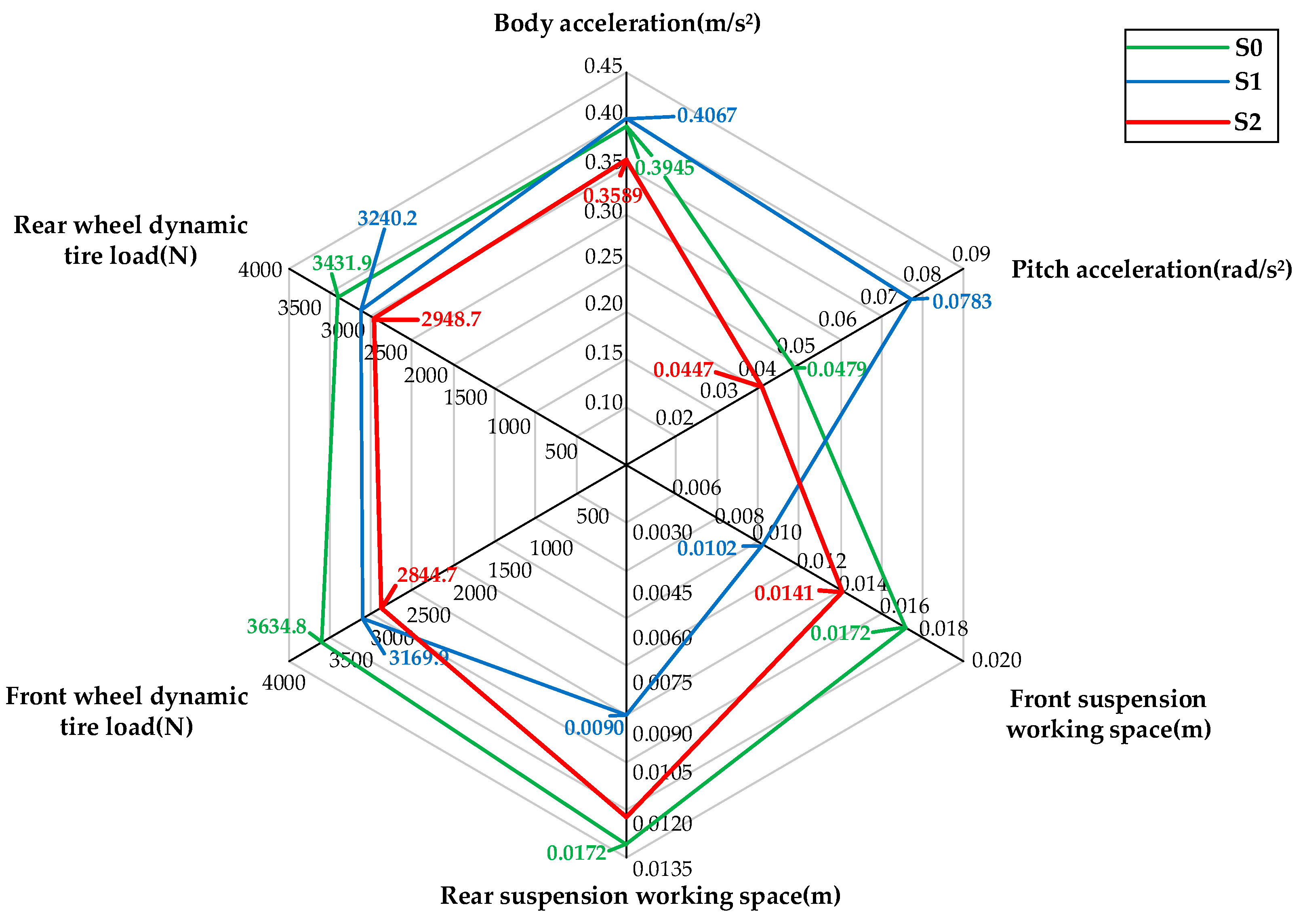
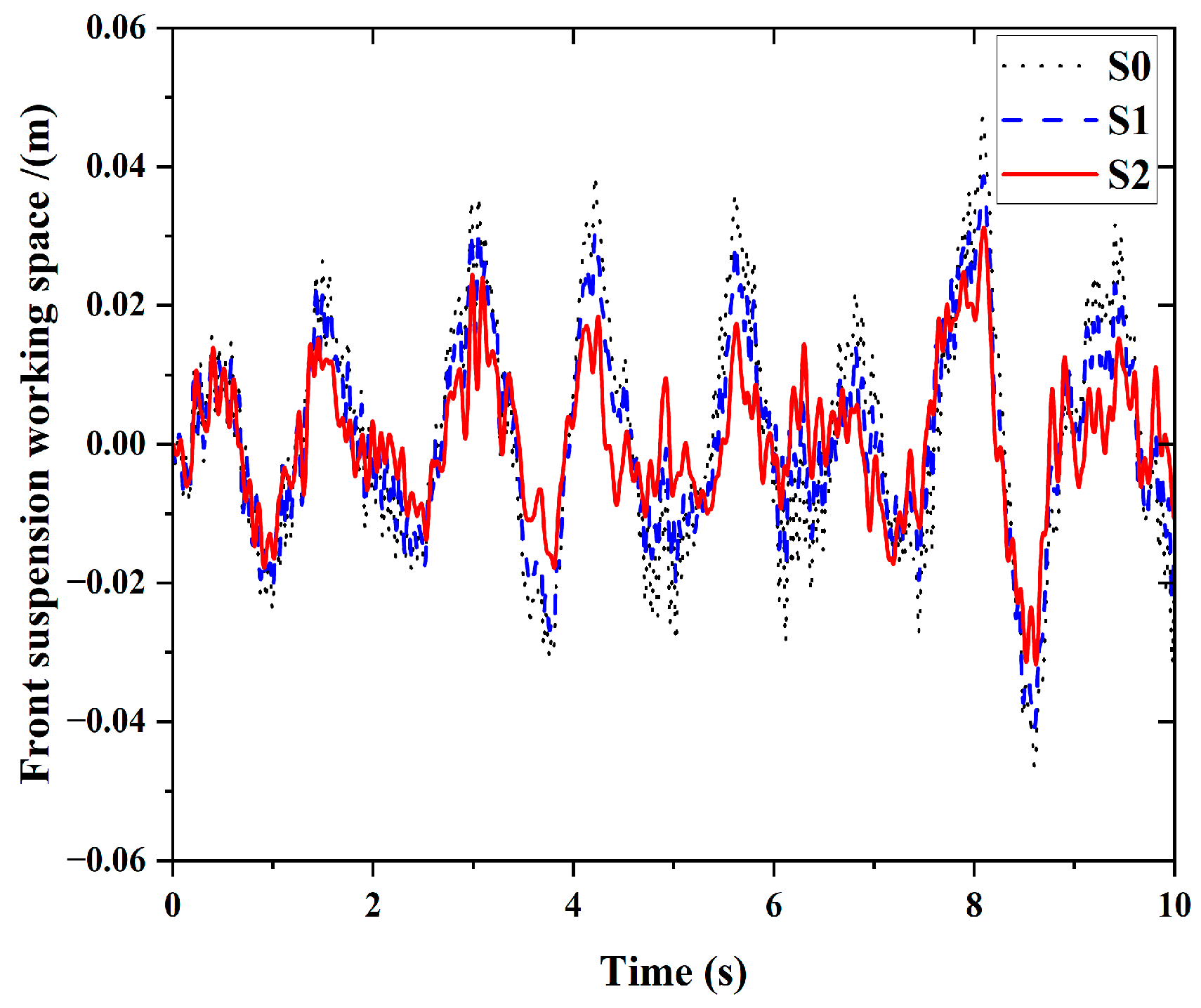
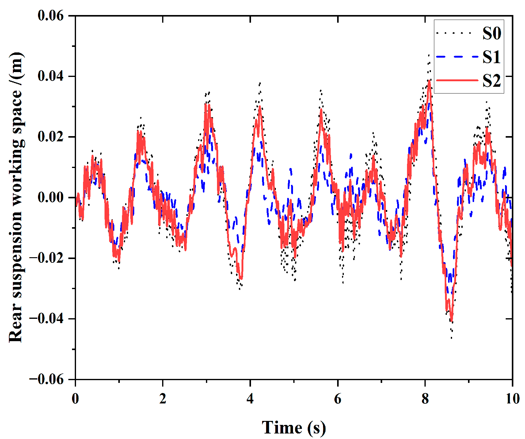
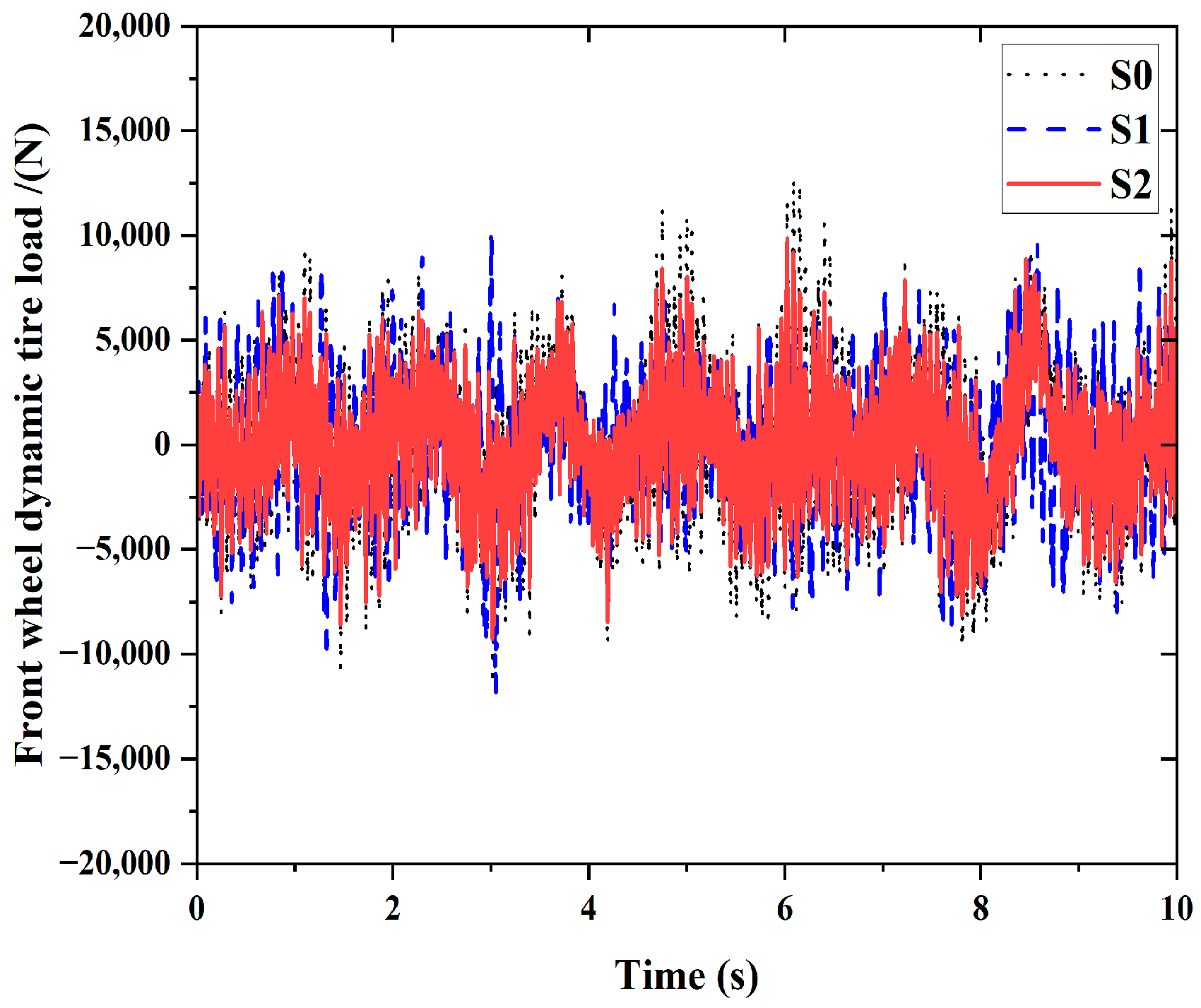
| Performance Index | Body Acceleration (m/s2) | Pitch Acceleration (rad/s2) | Front Suspension Working Space (m) | Rear Suspension Working Space (m) | Front Wheel Dynamic Tire Load (N) | Rear Wheel Dynamic Tire Load (N) | |
|---|---|---|---|---|---|---|---|
| S0 | RMS | 0.3945 | 0.0479 | 0.0172 | 0.0130 | 3634.8 | 3431.9 |
| S1 | RMS | 0.4067 | 0.0783 | 0.0102 | 0.0090 | 3169.9 | 3240.2 |
| S2 | RMS | 0.3589 | 0.0447 | 0.0141 | 0.0123 | 2844.7 | 2948.7 |
| Performance Index Decrease | Body Acceleration (%) | Pitch Acceleration (%) | Front Suspension Working Space (%) | Rear Suspension Working Space (%) | Front Wheel Dynamic Tire Load (%) | Rear Wheel Dynamic Tire Load (%) |
|---|---|---|---|---|---|---|
| S1 | −3.1 | −63.40 | 40.60 | 30.7 | 12.7 | 5.6 |
| S2 | 9.0 | 6.70 | 18.0 | 5.40 | 21.7 | 14.1 |
Disclaimer/Publisher’s Note: The statements, opinions and data contained in all publications are solely those of the individual author(s) and contributor(s) and not of MDPI and/or the editor(s). MDPI and/or the editor(s) disclaim responsibility for any injury to people or property resulting from any ideas, methods, instructions or products referred to in the content. |
© 2024 by the authors. Licensee MDPI, Basel, Switzerland. This article is an open access article distributed under the terms and conditions of the Creative Commons Attribution (CC BY) license (https://creativecommons.org/licenses/by/4.0/).
Share and Cite
Huang, R.; Yin, A.; Shen, Y.; Du, F.; Yang, X. Optimizing Hydro-Pneumatic Inerter Suspension for Improved Ride Comfort and Handling Stability in Engineering Vehicles Using Simulated Annealing Algorithm. World Electr. Veh. J. 2024, 15, 36. https://doi.org/10.3390/wevj15020036
Huang R, Yin A, Shen Y, Du F, Yang X. Optimizing Hydro-Pneumatic Inerter Suspension for Improved Ride Comfort and Handling Stability in Engineering Vehicles Using Simulated Annealing Algorithm. World Electric Vehicle Journal. 2024; 15(2):36. https://doi.org/10.3390/wevj15020036
Chicago/Turabian StyleHuang, Rongnan, Ao Yin, Yujie Shen, Fu Du, and Xiaofeng Yang. 2024. "Optimizing Hydro-Pneumatic Inerter Suspension for Improved Ride Comfort and Handling Stability in Engineering Vehicles Using Simulated Annealing Algorithm" World Electric Vehicle Journal 15, no. 2: 36. https://doi.org/10.3390/wevj15020036