Optimal Power Scheduling for a Medium Voltage AC/DC Hybrid Distribution Network
by
 ,
,
Zhenshan Zhu
1 ,
,
Dichen Liu
1,
Qingfen Liao
1,
Fei Tang
1,*,
Jun Jason Zhang
2 and
Huaiguang Jiang
3 1
School of Electrical Engineering, Wuhan University, Wuhan 430072, China
2
Department of Electrical and Computer Engineering, University of Denver, Denver, CO 80210, USA
3
National Renewable Energy Laboratory, Golden, CO 80401, USA
*
Author to whom correspondence should be addressed.
Sustainability 2018, 10(2), 318; https://doi.org/10.3390/su10020318
Submission received: 27 December 2017
/
Revised: 21 January 2018
/
Accepted: 22 January 2018
/
Published: 26 January 2018
(This article belongs to the Collection Power System and Sustainability)
Abstract
:With the great increase of renewable generation as well as the DC loads in the distribution network; DC distribution technology is receiving more attention; since the DC distribution network can improve operating efficiency and power quality by reducing the energy conversion stages. This paper presents a new architecture for the medium voltage AC/DC hybrid distribution network; where the AC and DC subgrids are looped by normally closed AC soft open point (ACSOP) and DC soft open point (DCSOP); respectively. The proposed AC/DC hybrid distribution systems contain renewable generation (i.e., wind power and photovoltaic (PV) generation); energy storage systems (ESSs); soft open points (SOPs); and both AC and DC flexible demands. An energy management strategy for the hybrid system is presented based on the dynamic optimal power flow (DOPF) method. The main objective of the proposed power scheduling strategy is to minimize the operating cost and reduce the curtailment of renewable generation while meeting operational and technical constraints. The proposed approach is verified in five scenarios. The five scenarios are classified as pure AC system; hybrid AC/DC system; hybrid system with interlinking converter; hybrid system with DC flexible demand; and hybrid system with SOPs. Results show that the proposed scheduling method can successfully dispatch the controllable elements; and that the presented architecture for the AC/DC hybrid distribution system is beneficial for reducing operating cost and renewable generation curtailment.
1. Introduction
The power system has been dominated by the AC grid for a long time, since AC voltage can be easily changed by transformers, and the power supply radius [1] of the AC system is larger. DC voltage was difficult to be changed in the past. However, the progress in the power electronic area has made DC voltage transformation [2] much easier and more effective. Moreover, the adoption of DC loads [3] (e.g., electric vehicles, data centers) and DC based sources (e.g., photovoltaic systems, fuel cells) has increased greatly in recent years [4,5]. As a result, the DC distribution network now attracts more attention than before.
The DC distribution systems contains the following benefits [6,7]. First, the DC/AC and AC/DC conversion stages in the AC systems can be avoided in the DC systems, because many renewable energy sources (RESs) like wind power and photovoltaic (PV) generation usually produce DC power directly, or produce DC first then it is converted to AC. Moreover, considerable emerging new loads like electric vehicles are also using DC systems. Hence, DC distribution systems can improve system efficiency by reducing conversion losses. Second, power quality and reliability can be improved by using DC systems. Third, the short current at one load can be separated by the converter in the DC system. Finally, the disadvantages of AC systems, including frequency reactive power flow, synchronization, and harmonics can be eliminated in DC systems.
DC distribution systems have been widely researched at low voltage level, especially in the microgrid. In ref. [8], A hybrid network composed of AC and DC microgrids was investigated. In [9], a DC demand response program is proposed for the DC distribution network integrated with distributed generators. However, network constrains are always ignored in these studies, since the systems are of small scale. At the medium-voltage level, DC distribution systems are often used in the area of offshore wind integration [10], electric vehicle charging station [7], and ship power networks [11]. In [10], a design of a power management control for an offshore DC distribution system for induction motor drives is proposed. In [7], a common DC bus architecture is presented for an electric vehicle charging station. In [11], a megawatt scale, medium voltage, medium frequency resonant dual active bridge dc-dc converter is studied for the medium voltage DC (MVDC) ship power networks. However, these studies mainly focus on control strategies, and do not consider large network operation constraints.
In spite of the various benefits of the DC system, both AC and DC loads are important in future distribution systems; the most practical architecture to eliminate unnecessary energy conversion is a hybrid AC/DC distribution network [12]. The architectures of the medium voltage hybrid AC/DC distribution system are usually traditional radial structures [13]. The radial architecture leads to a simple protection scheme. However, this type of architecture may cause large renewable generation curtailment when the penetration is high. Thus, this paper proposes a looped medium voltage AC/DC hybrid distribution network architecture based on AC soft open point (ACSOP) and DC soft open point (DCSOP). This architecture can achieve flexible power flow control and high renewable generation penetration.
The SOP has been studied in [14,15] for the AC distribution system to enhance the system performance, in terms of power loss minimization, feeder load balancing, and voltage profile improvement. However, the SOPs in these researches are all for AC systems, which are based on back-to-back voltage-source converters (VSC). This type of SOP is classified as ACSOP in this paper. Also, another type of SOP for a DC system based on a galvanically isolated bidirectional DC/DC converter is proposed and classified as DCSOP. The control modes as well as the operation model of DCSOP are then discussed.
Besides, DC flexible demand [9] is another key feature of the DC distribution system, which is useful for energy management. To the best knowledge of the authors, this is the first study in the literature combining all these elements in a hybrid AC/DC distribution system in a dynamic optimal power flow (DOPF) framework, including AC and DC flexible demands, AC and DC SOPs, energy storage systems (ESSs), fuel cells, renewable generation, and other units.
In short, this paper proposes a framework for the future medium voltage hybrid AC/DC distribution network, and focuses on the optimal operation of the proposed framework under renewable energy integration. The main objective of the proposed power scheduling scheme is to minimize the operating cost and reduce the curtailment of renewable generation.
The key contributions of this research are as follows:
- (1)
- The concept of DCSOP is proposed and the detailed model of DCSOP is presented.
- (2)
- A medium voltage AC/DC hybrid distribution network architecture based on ACSOP, DCSOP and interlinking converter is proposed to increase the renewable penetration and reduce operation cost.
- (3)
- An energy management scheme based on DOPF considering multiple key elements of the hybrid distribution system is proposed.
2. System Description
The traditional medium voltage distribution network, which is usually based on a radial structure, has low reliability when a fault occurs in the network. For the great increase of sensitive loads and the large-scale integration of renewable energy in the future, a more reliable distribution network is needed. To better meet the demand of the consumers and improve energy conversion efficiency, this paper proposes a flexible looped AC/DC hybrid medium-voltage distribution network.
2.1. Generic Description of the AC/DC Hybrid Distribution Network
The simplified structure of the proposed distribution network is shown in Figure 1. The hybrid grid consists of a looped AC subgrid and a looped DC subgrid. The AC subgrid is connected to the high voltage AC (HVAC) power grid by a transformer. The DC subgrid is connected to the HVAC grid or high voltage DC (HVDC) grid by a converter, which operates at constant voltage control mode to stabilize the voltage of the DC subgrid. The two subgrids are interconnected through a bi-directional AC-DC converter which enables power transfer between the two subgrids. Moreover, when there is a power failure in one subgrid, the interlinking converter can be used as a backup power source. As shown in Figure 1, The AC and DC feeders are connected by ACSOP and DCSOP, respectively. These two types of SOPs (or switches) are normally closed and able to control the power flow through them. Unlike the traditional distribution network which is looped by a normally open switch and operates radially, the proposed hybrid distribution network looped by the normally closed SOPs can operate as a ring or mesh. By replacing the mechanical tie switches with SOPs which are based on power electronic devices, the control of the distribution network can be faster and more flexible. The meshed network architecture and the controllability of power flow are beneficial for renewable generation integration and operating cost reduction. This will be discussed in Section 4.
Various distributed generators (DGs) (e.g., wind power, PV generation, fuel cell, and diesel generator) are connected to the medium voltage AC/DC distribution network. To suppress fluctuations caused by intermittent renewable generation, energy storage systems are essential.
Under the medium voltage distribution network layer, the low voltage distribution networks could be DC microgrids or AC microgrids. In addition to the traditional AC loads, DC loads like electric vehicles can be supplied directly by hybrid distribution networks, which can reduce massive converter links and power losses.
2.2. Flexible Demand
The flexible demand [9] is equivalent to the spinning reserve to a certain extent, and can shift power consumption from peak load hours to light load period, reducing the need for spinning reserves. Currently, the flexible demand mainly consists of AC demand, such as air conditioning and refrigeration. However, as DC loads as from electric vehicles increase and DC distribution networks develop, DC demands will be an important part of the demand side resources. Both AC and DC flexible demand can respond to the power system, and contribute to balancing the supply and demand of the distribution system.
2.3. SOP
A SOP [14,15] is a power electronic device placed where the traditional mechanical tie switch is installed. It can control the active power of the feeders connected to it and provide voltage support. The traditional ACSOP and the proposed DCSOP in this study are the two types of SOPs, which are used in AC and DC distribution networks, respectively.
2.3.1. ACSOP
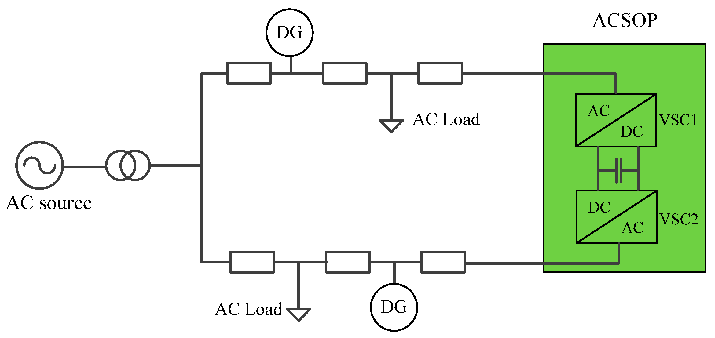
The single line diagram of an ACSOP is illustrated in Figure 2. The ACSOP is based on two back-to-back VSCs located at the endpoints of the two AC distribution feeders. Insulated gate bipolar transistors (IGBT) are used by the two VSCs to build the desired voltage waveforms, and the two VSCs are connected via a dc link to reduce voltage ripple and provide an energy buffer.
The system with an ACSOP, contains the advantages [15] of both the meshed and radial distribution systems (i.e., high reliability and simplified protection strategy).
Other benefits [16] of an AC distribution network equipped with an ACSOP are:
- (1)
- Flexible Power Flow Control: The back-to-back VSCs can generate the desired waveforms separately, enabling independent reactive power control at both interface terminals, which is useful for system loss reduction.
- (2)
- Instantaneous Voltage Control: The ACSOP controls its terminal voltage waveforms dynamically in milliseconds, enabling voltage profile improvement throughout the system.
- (3)
- Fault Isolation: In the system whose feeders are connected by a mechanical tie switch, the faults and disturbances can spread across the feeders. In contrast, faults and disturbances can be isolated from other normal feeders via ACSOPs, and the over-current is limited since the fault current is controllable.
With the ability to control active and reactive power flexibly and instantaneously, an ACSOP can operate under both normal and abnormal operating conditions. However, this study focuses on the normal operating conditions, under which a power flow control mode [17] is used to operate the ACSOP. Such a power flow control mode provides de-coupled control of active and reactive power, and is integrated into the proposed dispatch scheme to increase renewable generation penetration and reduce operation cost.
2.3.2. DCSOP
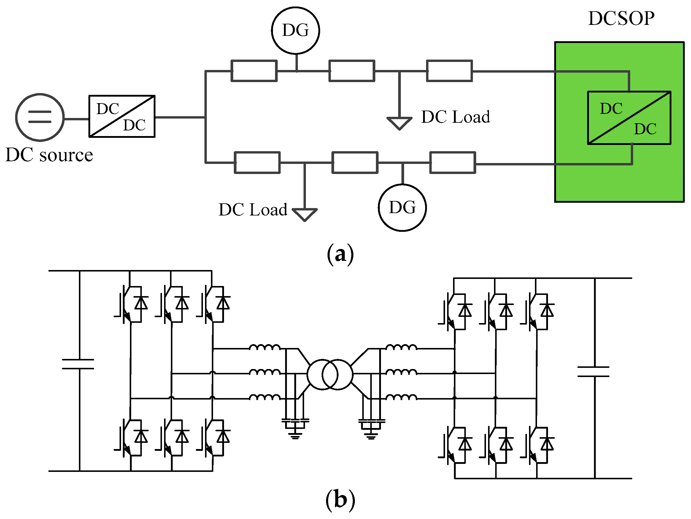
Similar with the ACSOP, a DCSOP is located at the end of the DC feeders, and connects the two DC feeders by a DC/DC converter. The single line diagram of a DCSOP is shown in Figure 3. In this study, the galvanically isolated bidirectional DC/DC converter based on VSCs and a high-frequency transformer [18] is used for the DCSOP. The DCSOP can achieve electrical isolation between DC feeders, and function as a DC breaker to isolate short fault occurs in the MVDC grid. Since there is no reactive power problem in the DC distribution system, the DCSOP does not provide reactive power support. However, the DCSOP can control the active power flow through it, and regulate its terminal voltage to improve the voltage profiles of the distribution system.
The control modes of a DCSOP are shown in Table 1. Under normal operating condition, one of the two VSCs controls the AC voltage between the VSCs to maintaining a constant AC-side voltage for a stable and balanced power flow through the transformer. The other VSC controls the DC power through the DCSOP. When a fault occurs, the DCSOP switches the control mode to provide voltage support for the non-fault area. In this case, the VSC near the fault area controls the terminal DC voltage and the other VSC controls the AC voltage between the VSCs.
3. Proposed Dispatch Scheme
The optimal operation of medium voltage hybrid AC/DC distribution network is based on the load and renewable energy generation forecast in a 24-h horizon. To ensure the maximum utilization of renewable generation and decrease the operation cost under the constraints of security, the following mathematical model is constructed.
3.1. Objectives
The objectives of the proposed DOPF consist of the following two parts:
(1) Minimize curtailment of renewable generation
The objective minimizes the total curtailment of renewable energy across the optimization horizon, which is formulated as
where t is the time-step; is the renewable generation curtailment at each time-step; is the number of time-steps; is the length of each time-step.
(2) Minimize total operation cost
The objective minimizes the total costs of the distributed energy resources (DERs) and power purchased from the external grid over the scheduling horizon. The DERs used in this study include renewable generation, fuel cell, and diesel generator as shown in Figure 1. Since the wind power and PV generation do not consume fuel, their operation costs are assumed to be 0. The operation cost is formulated as
where k is the number of DERs; and are the electricity prices and operating cost of the DER at each time step, respectively; is the power purchased from external grid; is the active power generation of DER k; is the cost of flexible load ; is the set of flexible load.
(3) Combination of the two objectives
The above two objective functions are combined into one overall objective function to form a scalar optimization problem, as follows
where is the total predicted renewable generation including wind and solar energy at each time-step; T is the set of time-steps; is the active loads at bus i; is the set of AC buses; is the set of DC buses; and are the reference values to normalize the two objectives, is the sum of predicted renewable generation, is the cost of purchased power from the external grid when DERs are not considered; and are the weights for objective and , respectively; the values of and are based on the need of the network operator, in this study, and are 0.5 and 0.5, respectively.
3.2. Power Balance Equations
In order to obtain the status information of the given distribution network (e.g., node voltages and branch powers), a full AC/DC DOPF for power management should be formulated.
(1) Power balance equations of the AC subgrid
where and are the active and reactive power injection at bus i, respectively; and are the active and reactive loads at bus i; and are the node voltages of bus i and bus j, respectively; , , and are the conductance, electrical susceptance, and phase angle difference between bus i and bus j, respectively.
(2) Power balance equations of the DC subgrid
3.3. Security Constraints
The voltage at each bus is limited by
where, is the node voltage of bus i at time t; and are the lower and upper voltage limits of bus i, respectively; It is assumed that the lower and upper voltage limits remain fixed across the optimization horizon.
The line loading limits are formulated as
where represents the apparent power flow of line m; is the maximum power flow allowed.
3.4. Constraints of the Distributed Generator (DG) Operation
(1) Firm distributed generation
Firm generation [19] represents the generation which must be taken and cannot be curtailed. Usually firm generation is equivalent to negative load. In this study, some of the wind and PV generation is set as firm generation.
(2) Nonfirm distributed generation
Nonfirm distributed generation [19] has a maximum output at each time-step, and the output of nonfirm generation is controllable. In this research, nonfirm generators are composed of dispatchable units including diesel generators, fuel cells, and part of wind and PV generation. The corresponding constraints are as follows:
where, is the number of nonfirm generators; is the active power generation of DG, and is the corresponding upper limits; and are the ramp-down rate and ramp-up rate, respectively.
3.5. Constraints of the Energy Storage System (ESS)
ESS can absorb energy during off-peak demand periods, and sell it during peak power demand hours. It reduces the need for conventional peak power generation plants. The constraints of ESSs are related to the maximum capacity and state of charge (SOC). For simplicity, the charging power and discharge power are assumed to be fixed during each time interval. Equations (14) and (15) give the charging and discharging limits of ESS. Equation (16) guarantees that charging and discharging do not occur simultaneously.
where, and are the charging and discharging power of ESS; and are the corresponding limits; and represent the charging and discharging state of ESS. If is 1 and is 0, the ESS is at charging state. Otherwise if is 0 and is 1, the ESS is at discharging state.
Over-charge and over-discharge will reduce the life of ESS. Thus, the SOCs of ESS should be bounded by Equation (17). As shown in (18), the SOC at each time-step depends on the charging or discharging power at the previous time-step, as well as on the historical SOCs. Besides, the SOCs at the beginning of the day and the end of the day are expected to be the same.
where, and are lower and upper limits of SOCs; is the capacity of ESS; and are the charging and discharging efficiency; and are the initial and final time-steps in a day.
3.6. Constraints of the Interlinking Converter
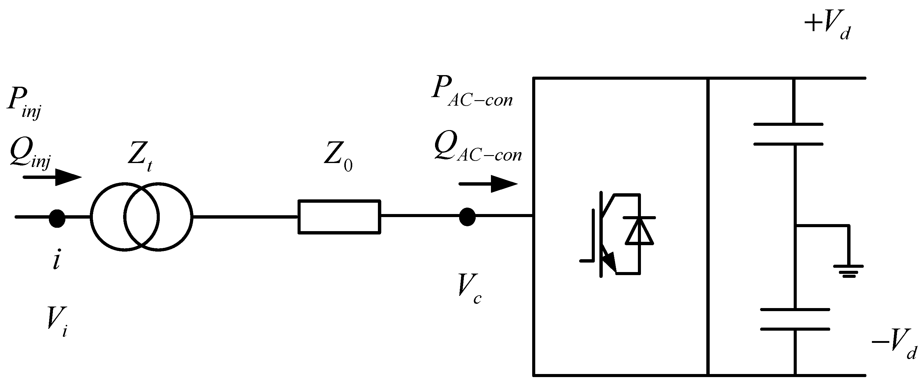
The VSC based interlinking AC-DC converter can control active and reactive power independently, and exchange power between the AC and DC subgrids based on the higher-level optimization scheme. Under normal conditions, the converter operates at PQ control mode [17]. When a fault occurs in the distribution network, the interlinking converter switches the PQ control mode to constant voltage control mode (constant DC voltage or constant AC voltage based on the fault location) to provide voltage support to the non-fault area. As shown in Figure 4, the converter is connected to the AC grid through a transformer. The equivalent impedances of the transformer and the phase reactor are represented as and , respectively.
The constraints of the interlinking converter can be formulated as follows [20]:
where and are the active power and reactive power from the AC grid to the transformer, respectively; and are the voltage magnitudes of node i and the converter AC terminal; and are the corresponding voltage angles. is the capacity of the converter; is the active power injected to the interlinking converter at the AC side; is the reactive power absorbed by the converter; is the converter power loss; , , and are the loss coefficient of the converter; is the converter current; and are the terminal AC line voltage and DC voltage to earth, respectively; and are the corresponding voltage upper limits.
3.7. Constraints of Trading with Grid
The power exchange between the distribution network and theexternal grid is constrained by
where is the purchased power from the external grid; is the exported power to the external grid; and are the binary variables for power flow direction; and are the upper limits, respectively.
3.8. Constraints of Flexible Demand
Two types of controllable loads, i.e., interruptible loads and deferrable loads [21], are considered in this study. Both types of controllable loads can be AC or DC loads. The interruptible loads are allowed to be shed, while the deferrable loads can be shifted across a dispatch horizon.
For each load , its active power is denoted as , which is constrained by
where and are the lower bound and upper bound of active power, respectively.
The deferrable loads are constrained as
The demand vector of each load can be denoted as . is the cost function of the flexible demand which represents the dissatisfaction of users under the power scheduling scheme .
The cost of the interruptible load [21] is related to the amount of shed load. It can be represented as
where is a coefficient greater than zero and is the predicted load. For an interruptible load, the cost function is nonzero if there is load shedding.
The cost of a deferrable load is related to the unfulfilled energy, and can be represented as
where is a coefficient greater than zero.
3.9. Constraints of SOP
In this section, the operation of ACSOP and DCSOP under normal operating conditions is considered.
(1) ACSOP
The power flow control mode in [17] is used for the ACSOP. In this mode, both VSCs generate voltage waveforms independently, resulting in a full (four-quadrant) control of the power flow at the two AC terminals. The operation of an ACSOP is shown in Figure 5. Three variables can be controlled independently, i.e., the output active power of VSC1 and the output reactive power of the two VSCs, which are denoted by , , and , respectively.
The operation of an ACSOP is constrained as follows
where, and are the active power from the two VSCs to the grid at time t, respectively; and are the reactive power, respectively; and are the corresponding ratings; is the loss of ACSOP; and are the loss coefficients of the two VSCs; and are the upper limits of the VSCs’ terminal voltages.
(2) DCSOP
Since there is no reactive power problem in a DC distribution network, only the active power needs to be considered. The constant power control mode is used to operate the DCSOP under normal operating. The operation of a DCSOP is constrained as follows
where, and are the active power from the two VSCs to the grid at time t; and are the maximum active power transferred by the VSCs; is the loss of DCSOP; and are the loss coefficients; and are the upper limits of the VSCs’ terminal voltages.
4. Case Study
In this section, the effectiveness of the proposed day-ahead power scheduling framework is verified in two cases.
4.1. Case 1
4.1.1. System Description
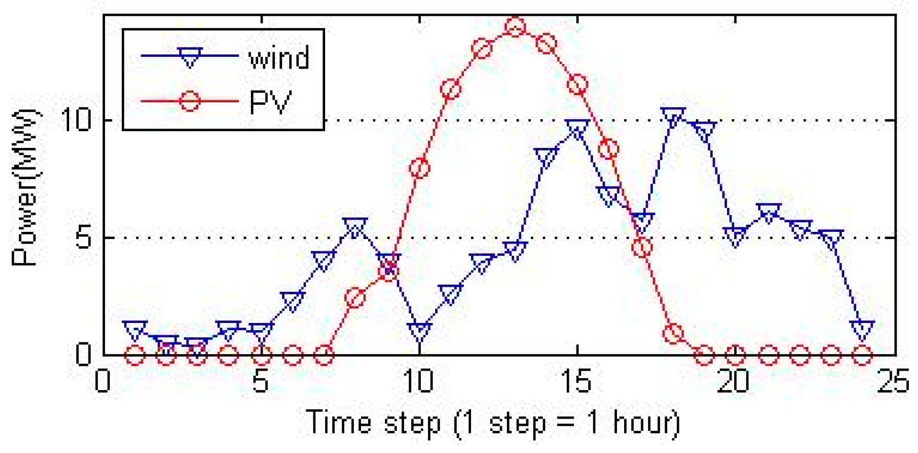
Figure 1 shows the line diagram of Case 1, which is a 20 kV AC/DC hybrid distribution network modified from [22]. The resistance data of the DC feeder is obtained by ignoring the reactance of the AC feeder. The DC subgrid is a ± 20 kV bipolar system. The generation of wind power at bus A9 and PV at bus A2 is not allowed to be curtailed. The renewable generation at bus A6, B6, and B14 can be curtailed (i.e., dispatchable). The locations of other DERs are shown in Figure 1. The time-series for generation of wind turbines and PV panels are shown in Figure 6. The total renewable generation is 67.2% of the loads, and 47.7% of the loads are DC. It is assumed that bus A11 is a deferrable load, while bus A12 and bus B12 are all interruptible loads. The cost coefficients for interruptible and deferrable loads are set as $1000/(MW2) and $100/MWh [21]. The day-ahead electricity price from the California Independent System Operator (CAISO) shown in Figure 7 is used for the simulation. The complete scheduling period is 24 h, with the time interval set to 1 h.
The following five scenarios whose simplified architecture diagram are shown in Figure 8, are used to illustrate the effectiveness of the proposed AC/DC DOPF model.
- (1)
- Scenario 1 which is a pure AC system with traditional radial architecture, and ignores the equipment, i.e., the AC/DC converter, DC flexible demand, and SOPs, is used as the reference to compare with other scenarios.
- (2)
- Based on Scenario 1, Scenario 2 is built by converting Feeder A1 and A2 into DC feeders.
- (3)
- Based on Scenario 2, Scenario 3 is built by adding an AC/DC converter which connects the AC subgrid and DC subgrid.
- (4)
- Based on Scenario 3, Scenario 4 is built by adding DC flexible demand, with the interruptible loads deployed at Bus A12 and the deferrable loads deployed at Bus A11.
- (5)
- Based on Scenario 4, Scenario 5 is built by adding an ACSOP between Bus B7 and Bus B14, and adding a DCSOP between Bus A6 and Bus A12, to form a normally closed looped network. The detailed description of Scenario 5 is shown in Figure 1.
4.1.2. Implementation
The DC OPF is a convex problem, and can be solved very efficiently. However, the AC OPF is nonconvex due to the nonlinearity of the physical parameters [23], i.e., active power, reactive power, and node voltage, as shown in Equations (6) and (7). As a result, the OPF for the AC/DC hybrid network is nonconvex [24]. Many methods have been developed to solve the OPF problems, such as trust region interior point algorithm, Lagrangian method, and primal-dual interior point method. However, these methods normally obtain a locally optimal solution [25]. In contrast, the convex relaxation method can convert the original problem into a convex one to obtain a globally optimal solution [23]. However, the OPF formulation in this study contains SOPs and is different from the standard OPF problem. Thus, the exactness of the convex relaxation method remains unknown and needs further research. Here, an efficient hybrid genetic algorithm–interior point method (GA–IPM) [26], which is a global optimization method, and can handle discrete variables easily, is used for calculations. The calculation is implemented in MATLAB, on a laptop (Hewlett-Packard, Chongqing, China), Intel (R) Core (TM) i7-6500U, CPU @ 2.50 GHz, 12 GB RAM. The average calculation time is 307.6 s.
4.1.3. Results and Discussion
The results for scenario 1 are shown in Figure 9. It is seen that the generation of the fuel cell and diesel generator between 16:00 and 19:00 is greater than the generation at other times. The reason is that the electricity price is high at these times, and more power generated by the fuel cell and diesel generator will result in less electricity purchased from the external grid. This reduces the total operating cost. The operating schedule of ESS is shown in Figure 9b. The charging power of ESS at bus A5 is high between 11:00–15:00, while the charging power of ESS at bus B13 is high between 13:00–15:00 and 17:00–19:00. These times are peak hours of renewable generation, when excessive generation of DGs may lead to voltage violation at certain buses. By charging the ESS at these times, the excess power is stored up, resulting in the reduction of renewable generation curtailment. The AC interruptible loads are shown in Figure 9c, and they are shed largely during high electricity price periods. The total curtailment amount of wind power and PV generation is 48.2 MWh, accounting for 9.8% of the available renewable generation across the whole day.
In scenario 2, Feeder A1 and A2 are converted into DC feeders. The results for scenario 2 are shown in Figure 10. It can be seen that the schedule for Feeder B1 and B2 in scenario 2 is the same as that in scenario 1, because the AC subgrid and DC subgrid are independent, and the settings for Feeder B1 and B2 are the same. The charging power of ESS at bus A5 is high at two time-steps, from 13:00 to 15:00, less than the charging time in scenario 1. The total curtailment amount of wind power is 15.0 MWh, while PV generation curtailment is 27.3 MWh. In total, 8.6% of the available renewable generation is curtailed across the whole day. Compared with scenario 1, the curtailment is reduced by 5.9 MWh. The results in scenario 2 show that the MVDC system has a larger renewable penetration level than MVAC system.
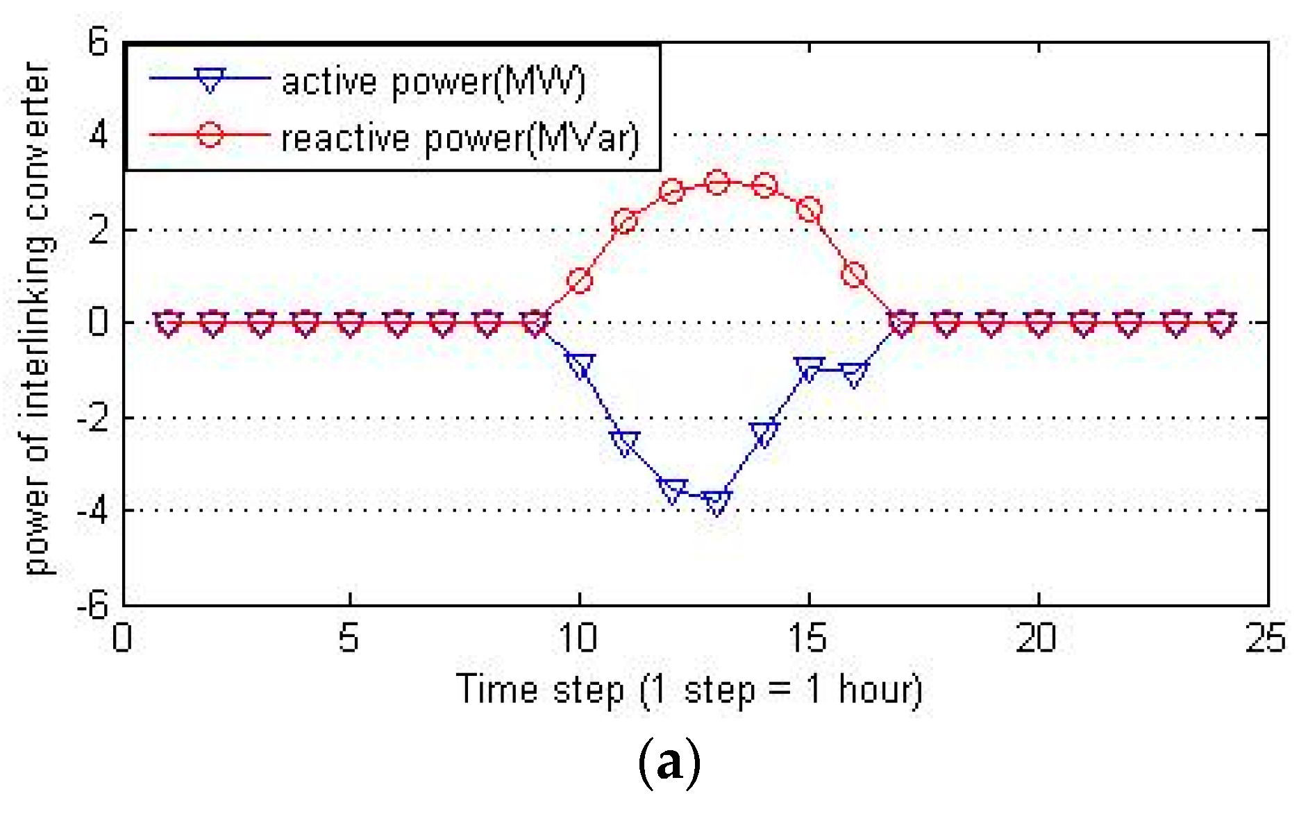
In scenario 3, a bi-directional AC/DC converter is used to connect the AC subgrid and DC subgrid. This enables power exchange between the two subgrids. Results of scenario 3 are shown in Figure 11. As shown in Figure 11a, the AC subgrid transfers 15.5 MWh to the DC subgrid between 9:00–16:00. This reduces the curtailment of renewable generation since part of the generation is shifted to DC subgrid, relieving the pressure of AC subgrid. Besides, the interlinking converter absorbs 15.4 MVarh reactive power, mitigating the voltage rising problem in AC subgrid at generation peak hours. Figure 11b shows the generation curtailment in scenario 3. The total curtailment is 28.6 MWh, accounting for 5.8% of the available renewable generation. Compared with scenario 2, the curtailment is reduced by 13.7 MWh.
In scenario 4, the fixed DC demands at bus A11and A12 are replaced by flexible DC demands, resulting in the further reduction of renewable generation curtailment. Figure 12a shows the schedule for both AC and DC flexible demands at the three buses. A positive value of the schedule means the power demand is shed, while a negative value means a power demand increment. It can be seen that both AC and DC interruptible loads are shed a lot when the electricity price is high (i.e., between 16:00–19:00), to reduce the total operation cost. In addition to the interruptible loads, the DC deferrable load between 9:00–16:00 (the peak renewable generation hours) is shed, and shifted to other non-peak generation hours. The shifted deferrable load is 14.2 MWh in total. The utilization of flexible DC demands in scenario 4 reduces the renewable generation curtailment by 11.7 MWh compared with scenario 3. Besides, the operation cost in scenario 4 is $1000 less than that in scenario 3. These results show that, flexible DC demands are beneficial in the operation of the AC/DC hybrid distribution network, for cost reducing and renewable energy integration.
In scenario 5, the two AC feeders are connected with an ACSOP, while the DC feeders are connected with a DCSOP. As shown in Figure 13, in the AC subgrid, the feeder B1 transfers active power to feeder B2 between 9:00–16:00, and the feeder B2 transfers active power to feeder B1 between 17:00–19:00. In the DC subgrid, the feeder A1 transfers active power to feeder A2 between 10:00–15:00. This is because 9:00–16:00 are the peak hours of PV generation at feeder B1. At the same time, the wind power generation at feeder B2 is relatively low. The feeder B1 is more likely to violate the voltage limits for its excessive generation integration. Thus, the generation power in feeder B1 is shifted to feeder B2 to relieve the pressure of feeder B2. Between 17:00–19:00, the PV generation decreases and the wind power generation increases. The generation power in feeder B2 is shifted to feeder B1 to be consumed. Similarly, in the DC subgrid, the feeder A1 transfers active power to feeder A2 during generation peak hours (i.e., 10:00–15:00) to avoid voltage violation in feeder A1. Compared with scenario 4, the generation curtailment is reduced by 15.98 MWh.
The results of the curtailment and costs of the five scenarios are summarized in Table 2. In the five scenarios, scenario 5 yields the best results. The curtailment in scenario 5 is 1.9% of the curtailment in scenario 1 which has a traditional radial architecture, and the operation cost is reduced by 23.4%. The case study illustrates that the use of DC flexible demands, SOPs, and interconnection of AC and DC subgrids is beneficial for reducing generation curtailment, and lowering the operation cost of the AC/DC hybrid distribution network. The reason is that the DC flexible demand can be equivalent to the spinning reserve which is able to shift power consumption across the dispatch horizon. The ACSOP and DCSOP have the ability of transferring active power, and the ACSOP is useful for reactive compensation. The connection of AC and DC subgrids with an interlinking converter enables power exchange between the two subgrids. All of these units contribute to optimizing the power flow of the AC/DC hybrid distribution network. Thus, the rising voltage and network congestion problems at generation peak hours are mitigated, and more DG penetration (i.e., less generation curtailment) is allowed. Furthermore, the generation curtailed can be regarded as revenue lost. The less the generation curtailment means the less power purchased from the external grid and the lower the operating cost.
4.2. Case 2
4.2.1. System Description
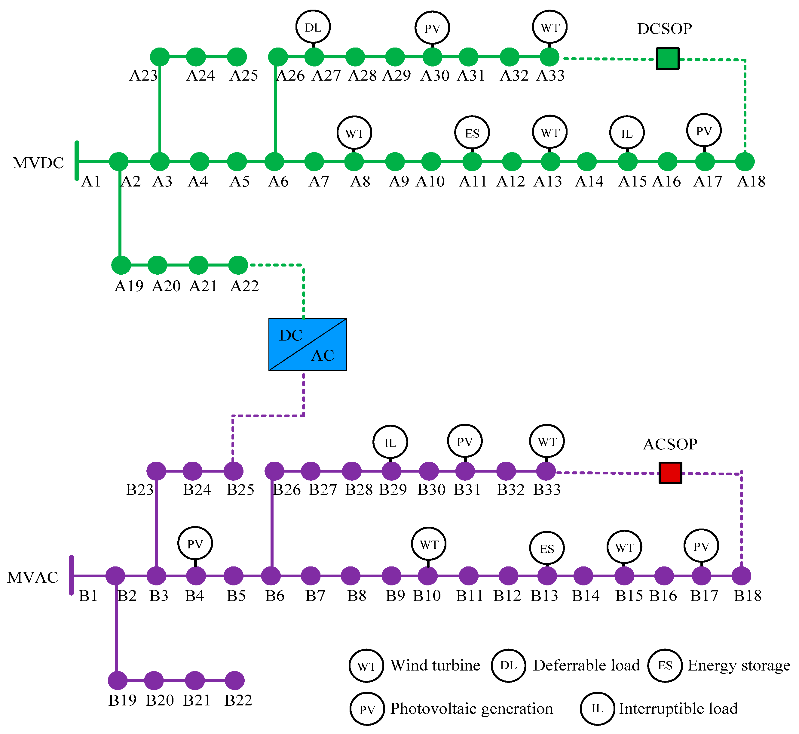
A larger case which consists of two IEEE 33-node distribution networks, was studied to further verify the proposed method. The system rated voltage is 12.66 kV, and the detailed data for the system can be obtained from [27]. The locations of DERs are shown in Figure 14. The renewable generators at Bus A13, A30, B15, and B31 are dispatchable. The generator capacity is 800 kW for both wind power and photovoltaic generation. The ACSOP is placed between Bus B18 and B33, while the DCSOP is placed between Bus A18 and A33. Similar to case 1, the following five scenarios are used to evaluate the performance of the proposed system.
- (1)
- Scenario 1 which is a pure AC system, is used as the reference to compare with other scenarios.
- (2)
- Based on Scenario 1, Scenario 2 is built by converting one IEEE 33-node AC system into a DC system.
- (3)
- Based on Scenario 2, Scenario 3 is built by adding an AC/DC converter which connects the AC subgrid and DC subgrid, at Bus A22 and B25.
- (4)
- Based on Scenario 3, Scenario 4 is built by adding a DC flexible demand, with the interruptible loads deployed at Bus A15 and the deferrable loads deployed at Bus A27.
- (5)
- Based on Scenario 4, Scenario 5 is built by adding an ACSOP between Bus B18 and Bus B33, and adding a DCSOP between Bus A18 and Bus A33.
4.2.2. Results and Discussion
The results of the curtailment and costs of Case 2 are shown in Table 3. It can be seen that, the results of scenario 5 are better than the other scenarios. The curtailment in scenario 5 is 11.3% of the curtailment in scenario 1, and the operation cost is reduced by 7.5%. These results show that the proposed method is still applicable in a larger system. It is worth mentioning that, the cost of power from wind and photovoltaic declined greatly over the past years, and keeps falling. In the United States, the capital cost of wind energy in 2004 was 65% of the early 1980s [28]. The cost of photovoltaic generation in Germany [29] was $0.49/kWh in 2005, and fell to $0.11/kWh in 2014. Moreover, according to the prediction of [29], photovoltaic generation cost will drop to $0.037/kWh in 2050, making solar power the cheapest form of electricity. In this context, renewable energy will be very competitive in the future. Also, power systems are requested to increase the penetration of renewable generation connected to the grid. Thus, this study is focused on the operation strategy of the distribution system, with the assumption that the cost of renewable generation is low enough to compete with traditional energy in the future. Using the capital cost data in [30], the annualized investment cost [30] of scenario 5 is $51,810 higher than scenario 1. Also, the annualized operation cost is $167,900 lower than scenario 1. The annualized operation cost reduction (compared with scenario 1) in scenario 5 is larger than the annualized investment cost increase, making scenario 5 more economical.
Generally, to obtain the benefits of SOPs and other controllable devices, the penetration of renewable generation should be high. In this way, the controllable devices can allow more renewable generation integration and lower the operation cost. Besides, with the development of converter technology, the cost of SOPs will decrease, which will further reduce the total investment cost. Moreover, SOPs can provide voltage support when a fault occurs in the distribution system, and improve the system reliability. Also, the high penetration of renewable energy is beneficial for environmental protection, providing extra social value.
5. Conclusions
This paper proposed an envisioned AC/DC hybrid distribution network architecture for the future medium voltage distribution network. An optimal power scheduling strategy for the proposed distribution network based on DOPF was developed to dispatch the ESSs, flexible demand, SOP, and controllable DGs. Two cases were solved to illustrate the advantages of the proposed distribution network architecture and the effectiveness of the scheduling strategy for one-day time-horizons. The results reveal that the scheduling strategy can efficiently manage power production and consumption for the day-ahead distribution network. The utilization of DC flexible demands, SOPs, and the interconnection of AC and DC subgrids can optimize the power flow of the hybrid distribution network. This reduces the curtailment of renewable generation significantly, and the total daily operation cost is decreased. A more detailed model considering uncertainties of renewable energy will be studied in future work.
Acknowledgments
This research was supported by the Chinese National Natural Science Foundation (51507116) and State Grid Corporation of China (Project: Research on the optimization methods for multistage grid structures considering the third defense line).
Author Contributions
Zhenshan Zhu proposed the concrete ideas of the proposed optimization method, and wrote the manuscript. Fei Tang performed the simulations and wrote the manuscript. Jun Jason Zhang and Huaiguang Jiang analyzed the data. Qingfen Liao debugged part of the programs. Dichen Liu checked the paper’s language. All of the authors revised the manuscript.
Conflicts of Interest
The authors declare no conflict of interest.
References
- Elsayed, A.T.; Mohamed, A.A.; Mohammed, O.A. DC microgrids and distribution systems: An overview. Electr. Power Syst. Res. 2015, 119, 407–417. [Google Scholar] [CrossRef]
- Reed, G.F.; Grainger, B.M.; Korytowski, M.J.; Taylor, E.J. Modeling, analysis, and validation of a preliminary design for a 20 kV medium voltage DC substation. In Proceedings of the IEEE Energytech, Cleveland, OH, USA, 25–26 May 2011; pp. 1–8. [Google Scholar]
- Zhang, P.; Yan, F.W.; Du, C.Q. A comprehensive analysis of energy management strategies for hybrid electric vehicles based on bibliometrics. Renew. Sustain. Energy Rev. 2015, 48, 88–104. [Google Scholar] [CrossRef]
- Deng, C.; Liang, N.; Tan, J.; Wang, G. Multi-Objective Scheduling of Electric Vehicles in Smart Distribution Network. Sustainability 2016, 8, 1234. [Google Scholar] [CrossRef]
- Jiang, H.; Zhang, Y.; Zhang, J.J.; Gao, D.W.; Muljadi, E. Synchrophasor-Based Auxiliary Controller to Enhance the Voltage Stability of a Distribution System with High Renewable Energy Penetration. IEEE Trans. Smart Grid 2015, 6, 2107–2115. [Google Scholar] [CrossRef]
- Hammerstrom, D.J. AC Versus DC Distribution Systems Did We Get it Right? In Proceedings of the IEEE Power Energy Society General Meeting, Tampa, FL, USA, 24–28 June 2007; pp. 1–5. [Google Scholar]
- Sparacino, A.R.; Grainger, B.M.; Kerestes, R.J.; Reed, G.F. Design and Simulation of a DC Electric Vehicle Charging Station Connected to a MVDC Infrastructure. In Proceedings of the IEEE Energy Conversion Congress and Exposition, Raleigh, NC, USA, 15–20 September 2012; pp. 1168–1175. [Google Scholar]
- Radwan, A.A.A.; Mohamed, Y.A.R.I. Assessment and Mitigation of Interaction Dynamics in Hybrid AC/DC Distribution Generation Systems. IEEE Trans. Smart Grid 2012, 3, 1382–1393. [Google Scholar] [CrossRef]
- Mohsenian-Rad, H.; Davoudi, A. Towards Building an Optimal Demand Response Framework for DC Distribution Networks. IEEE Trans. Smart Grid 2014, 5, 2626–2634. [Google Scholar] [CrossRef]
- Grainger, B.; Reed, G.; Mcdermott, T.; Mao, Z.; Kounev, V.; Tipper, D. Analysis of an offshore medium voltage DC microgrid environment—Part I: Power sharing controller design. In Proceedings of the IEEE PES T&D Conference and Exposition, Chicago, IL, USA, 14–17 April 2014; pp. 1–5. [Google Scholar]
- Agamy, M.; Dong, D.; Garces, L.; Zhang, Y.; Dame, M.; Wu, X. A High Power Medium Voltage Resonant Dual Active Bridge for MVDC Ship Power Networks. IEEE J. Emerg. Sel. Top. Power Electron. 2017, 5, 88–99. [Google Scholar] [CrossRef]
- Starke, M.; Tolbert, L.; Ozpineci, B. AC vs. DC distribution: A loss comparison. In Proceedings of the IEEE/PES Transmission and Distribution Conference and Exposition, Chicago, IL, USA, 21–24 April 2008; pp. 1–7. [Google Scholar]
- Eajal, A.A.; Shaaban, M.F.; Ponnambalam, K.; El-Saadany, E.F. Stochastic Centralized Dispatch Scheme for AC/DC Hybrid Smart Distribution Systems. IEEE Trans. Sustain. Energy 2016, 7, 1046–1059. [Google Scholar] [CrossRef]
- Long, C.; Wu, J.; Thomas, L.; Jenkins, N. Optimal Operation of Soft Open Points in Medium Voltage Electrical Distribution Networks with Distributed Generation. Appl. Energy 2016, 184, 427–437. [Google Scholar] [CrossRef]
- Bloemink, J.M.; Green, T.C. Increasing Distributed Generation Penetration using Soft Normally-Open Points. In Proceedings of the IEEE Power Energy Society General Meeting, Minneapolis, MN, USA, 25–29 July 2010; pp. 1–8. [Google Scholar]
- Bloemink, J.M.; Green, T.C. Increasing Photovoltaic Penetration with Local Energy Storage and Soft Normally-Open Points. In Proceedings of the IEEE Power Energy Society Genera Meeting, Detroit, MI, USA, 24–28 July 2011; pp. 1–8. [Google Scholar]
- Cao, W.; Wu, J.; Jenkins, N.; Wang, C.; Green, T. Operating Principle of Soft Open Points for Electrical Distribution Network Operation. Appl. Energy 2016, 164, 245–257. [Google Scholar] [CrossRef]
- Chub, A.; Vinnikov, D.; Blaabjerg, F.; Peng, F. A review of galvanically isolated impedance-source DC–DC converters. IEEE Trans. Power Electron. 2016, 31, 2808–2828. [Google Scholar] [CrossRef]
- Gill, S.; Kockar, I.; Ault, G.W. Dynamic Optimal Power Flow for Active Distribution Networks. IEEE Trans. Power Syst. 2014, 29, 121–131. [Google Scholar] [CrossRef] [Green Version]
- Beerten, J.; Cole, S.; Belmans, R. Generalized Steady-State VSC MTDC Model for Sequential AC/DC Power Flow Algorithms. IEEE Trans. Power Syst. 2012, 27, 821–829. [Google Scholar] [CrossRef] [Green Version]
- Shi, W.B.; Xie, X.R.; Chu, C.C.; Gadh, R. Distributed Optimal Energy Management in Microgrids. IEEE Trans. Smart Grid 2015, 6, 1137–1146. [Google Scholar] [CrossRef]
- Bignucolo, F.; Caldon, R.; Prandoni, V. Radial MV networks voltage regulation with distribution management system coordinated controller. Electr. Power Syst. Res. 2008, 78, 634–645. [Google Scholar] [CrossRef]
- Madani, R.; Sojoudi, S.; Lavaei, J. Convex Relaxation for Optimal Power Flow Problem: Mesh Networks. IEEE Trans. Power Syst. 2015, 30, 199–211. [Google Scholar] [CrossRef]
- Baradar, M.; Hesamzadeh, M.R.; Ghandhari, M. Second-Order Cone Programming for Optimal Power Flow in VSC-Type AC-DC Grids. IEEE Trans. Power Syst. 2013, 28, 4282–4291. [Google Scholar] [CrossRef]
- Huang, S.; Wu, Q.; Wang, J.; Zhao, H. A Sufficient Condition on Convex Relaxation of AC Optimal Power Flow in Distribution Networks. IEEE Trans. Power Syst. 2017, 32, 1359–1368. [Google Scholar] [CrossRef]
- Yan, W.; Liu, F.; Chung, C.Y.; Wong, K.P. A hybrid genetic algorithm-interior point method for optimal reactive power flow. IEEE Trans. Power Syst. 2006, 21, 1163–1169. [Google Scholar] [CrossRef]
- Baran, M.E.; Wu, F.F. Network reconfiguration in distribution systems for loss reduction and load balancing. IEEE Trans. Power Deliv. 1989, 4, 1401–1407. [Google Scholar] [CrossRef]
- Lantz, E.; Wiser, R.; Hand, M. The Past and Future Cost of Wind Energy. In Proceedings of the World Renewable Energy Forum, Denver, CO, USA, 13–17 May 2012; pp. 3508–3515. [Google Scholar]
- Fraunhofer ISE. Current and Future Cost of Photovoltaics. Long-Term Scenarios for Market Development, System Prices and LCOE of UtilityScale PV Systems, Study on Behalf of Agora Energiewende, Freiburg and Berlin. 2015. Available online: www.agoraenergiewende.de/fileadmin/Projekte/2014/KostenPhotovoltaik-2050/AgoraEnergiewende_Current_and_Future_Cost_of_PV_Feb2015_web.pdf (accessed on 12 February 2016).
- Wang, C.; Song, G.; Li, P.; Ji, H.; Zhao, J.; Wu, J. Optimal siting and sizing of soft open points in active electrical distribution networks. Appl. Energy 2017, 189, 301–309. [Google Scholar] [CrossRef]
Figure 1.
The structure of the medium voltage AC/DC hybrid distribution network.
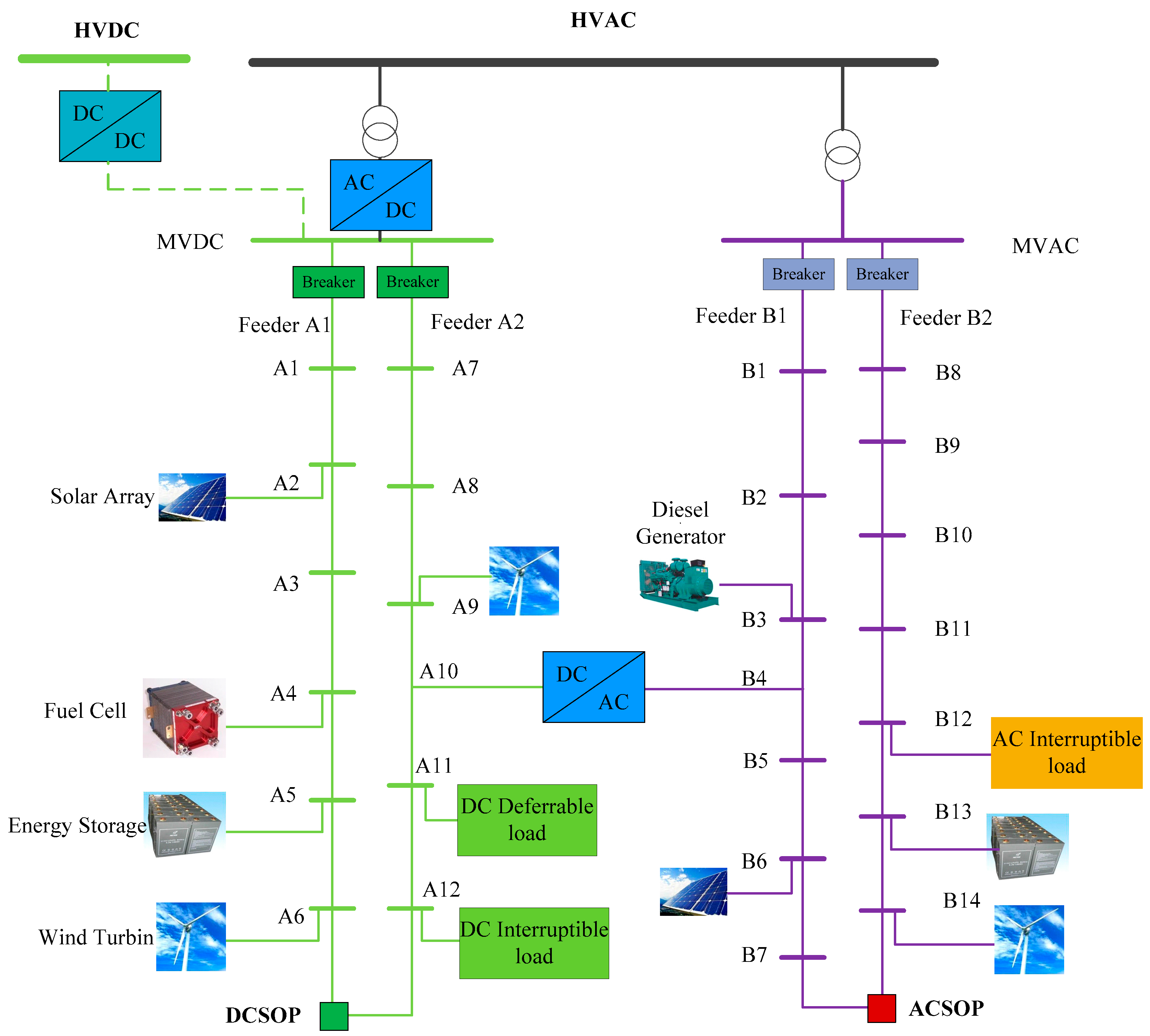
Figure 2.
Single line diagram of a simple distribution system with two feeders and an AC soft open point (ACSOP) connecting them. (DG = distributed generator, VSC = voltage-source converter).
Figure 2.
Single line diagram of a simple distribution system with two feeders and an AC soft open point (ACSOP) connecting them. (DG = distributed generator, VSC = voltage-source converter).

Figure 3.
(a) Single line diagram of a simple distribution system with two feeders and a DC soft open point (DCSOP) connecting them; (b) the structure of a DCSOP.
Figure 3.
(a) Single line diagram of a simple distribution system with two feeders and a DC soft open point (DCSOP) connecting them; (b) the structure of a DCSOP.

Figure 4.
Interlinking AC–DC converter.

Figure 5.
Operating curve of ACSOP.
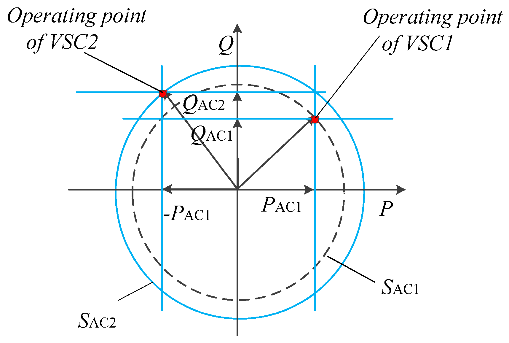
Figure 6.
Forecasted wind and photovoltaic (PV) generation.

Figure 7.
Day-ahead price from the California Independent System Operator (CAISO).
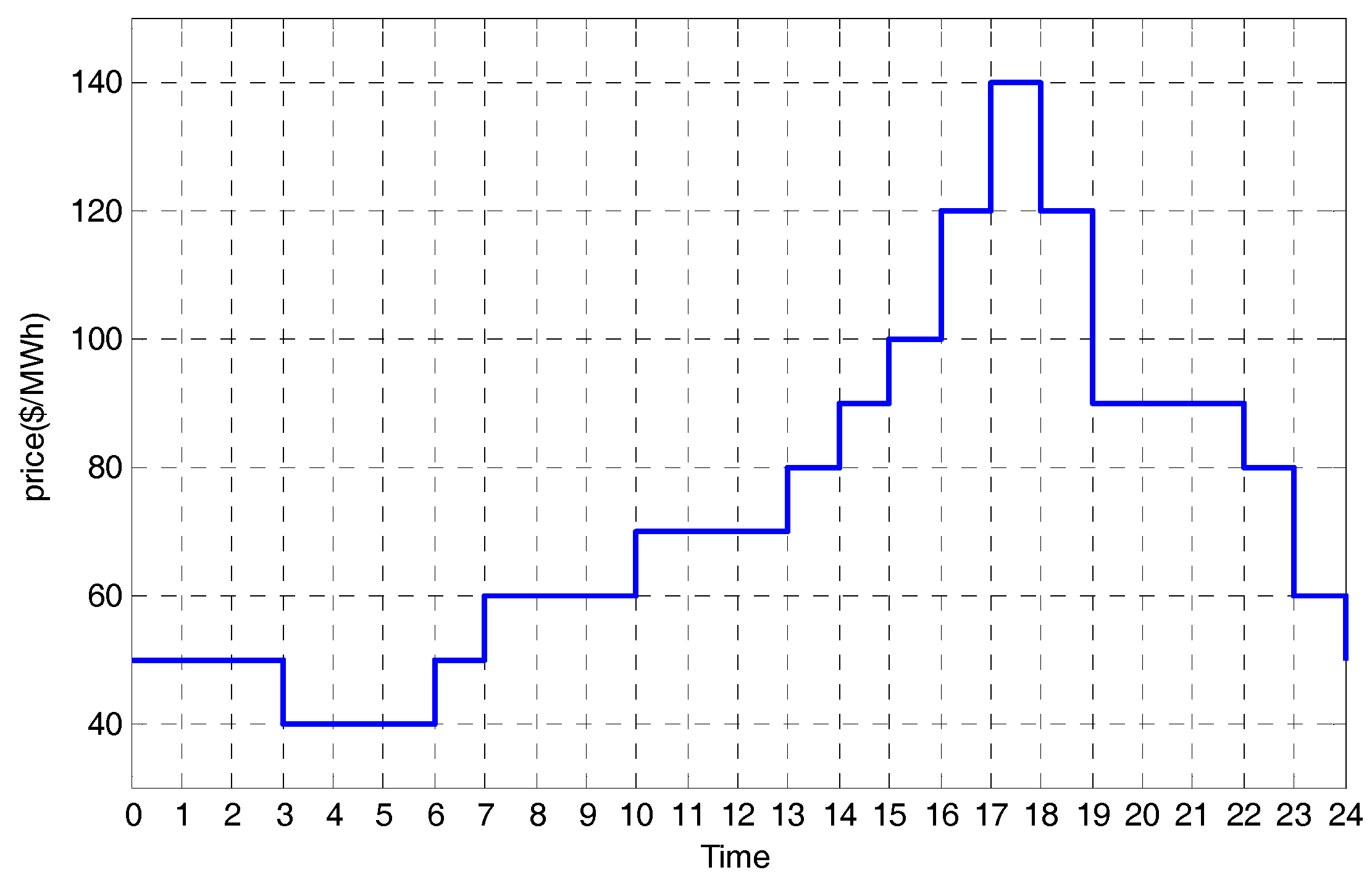
Figure 8.
The architecture of the 5 scenarios: (a) Scenario 1; (b) Scenario 2; (c) Scenario 3; (d) Scenario 4; (e) Scenario 5.
Figure 8.
The architecture of the 5 scenarios: (a) Scenario 1; (b) Scenario 2; (c) Scenario 3; (d) Scenario 4; (e) Scenario 5.
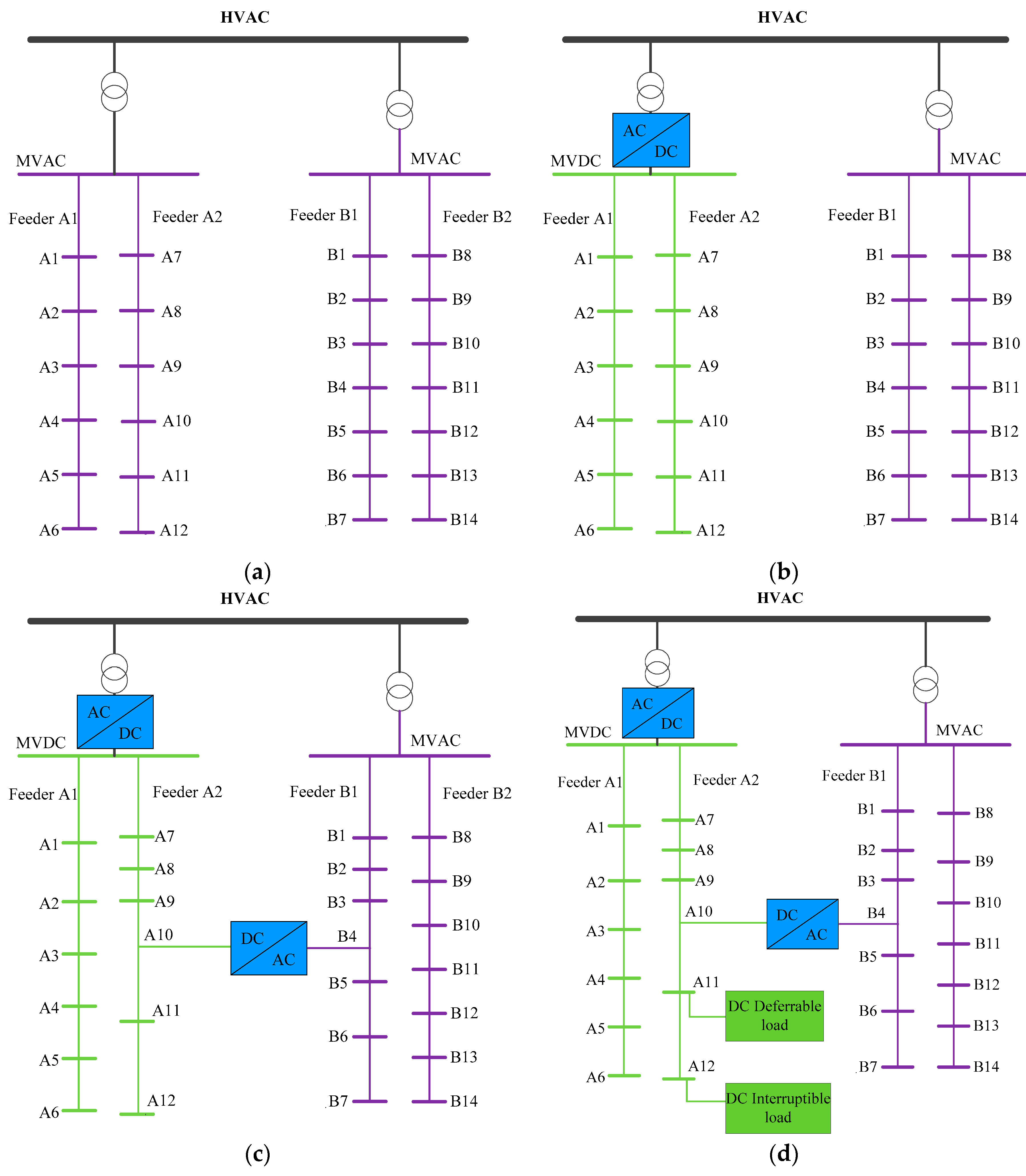
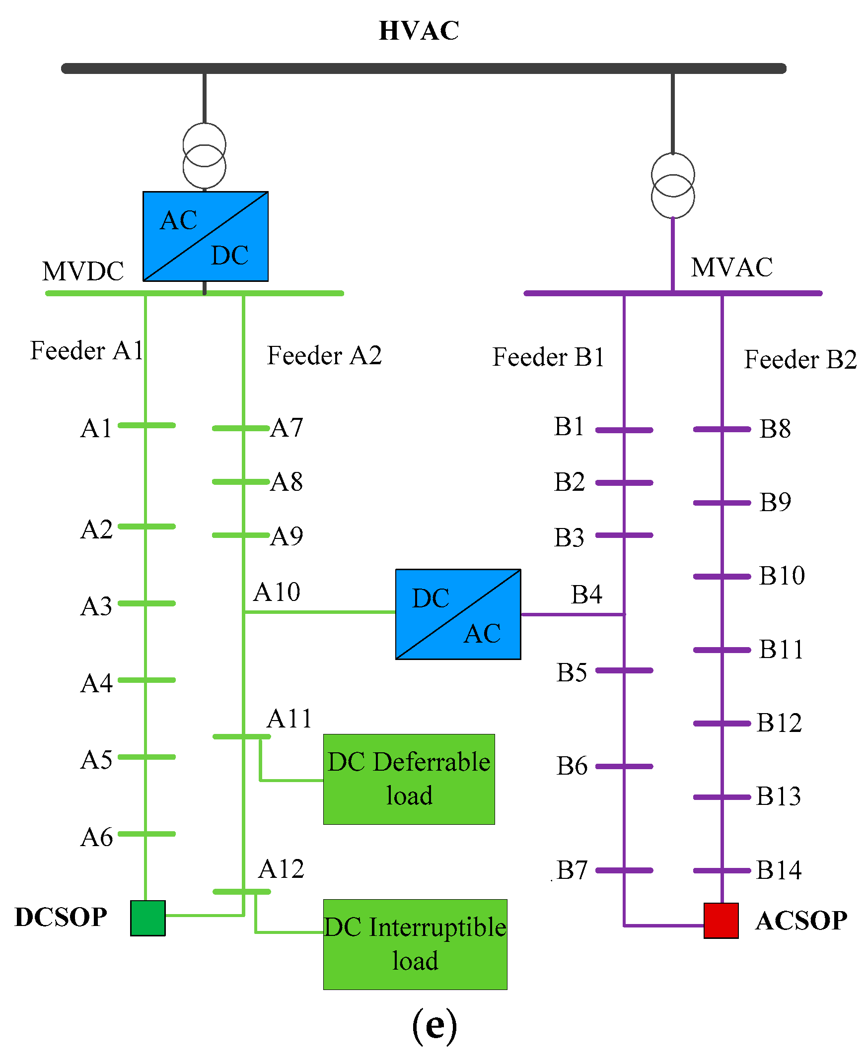
Figure 9.
Simulation results of scenario 1. (a) Generation of fuel cell and diesel generator; (b) energy storage systems (ESS) schedule; (c) the AC interruptible loads shed at bus B12; (d) renewable generation curtailment.
Figure 9.
Simulation results of scenario 1. (a) Generation of fuel cell and diesel generator; (b) energy storage systems (ESS) schedule; (c) the AC interruptible loads shed at bus B12; (d) renewable generation curtailment.
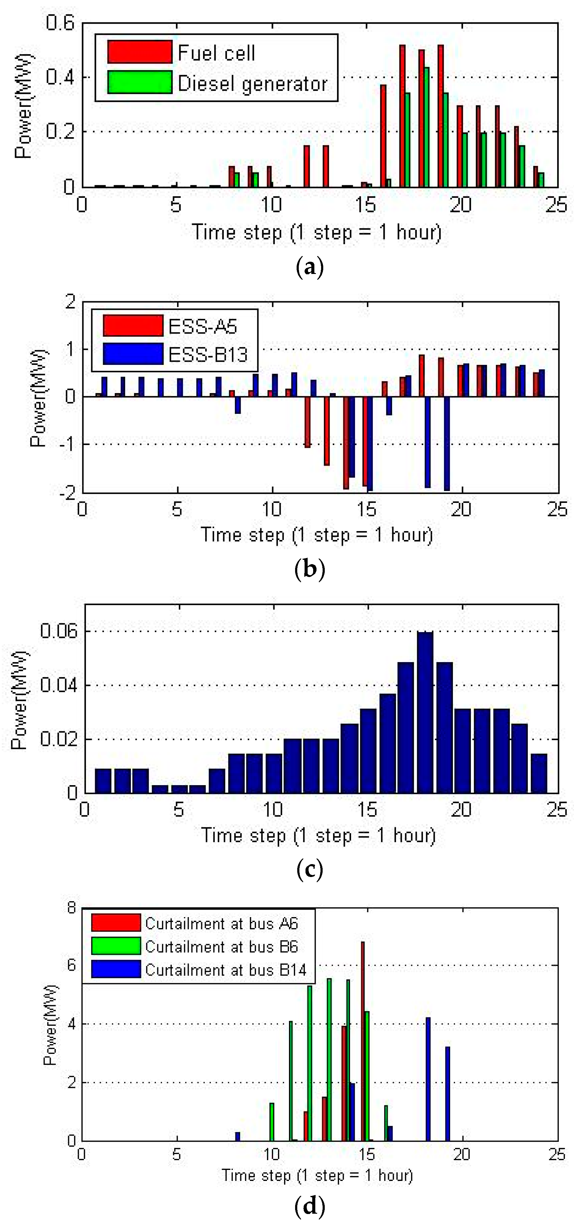
Figure 10.
Simulation results of scenario 2. (a) Generation of fuel cell and diesel generator; (b) ESS schedule; (c) renewable generation curtailment.
Figure 10.
Simulation results of scenario 2. (a) Generation of fuel cell and diesel generator; (b) ESS schedule; (c) renewable generation curtailment.
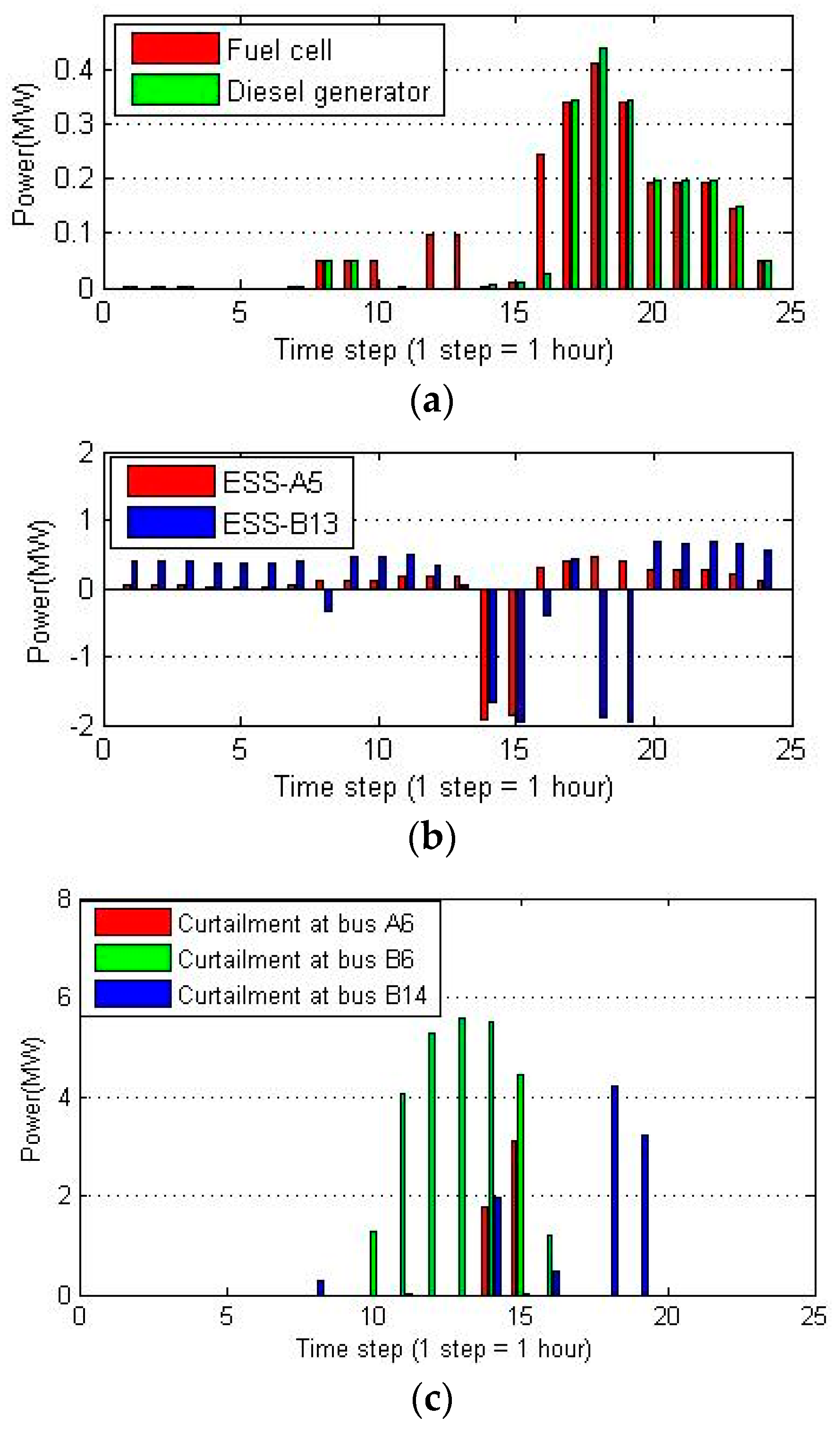
Figure 11.
Simulation results of scenario 3. (a) Active and reactive power of the interlinking converter; (b) renewable energy curtailment.
Figure 11.
Simulation results of scenario 3. (a) Active and reactive power of the interlinking converter; (b) renewable energy curtailment.

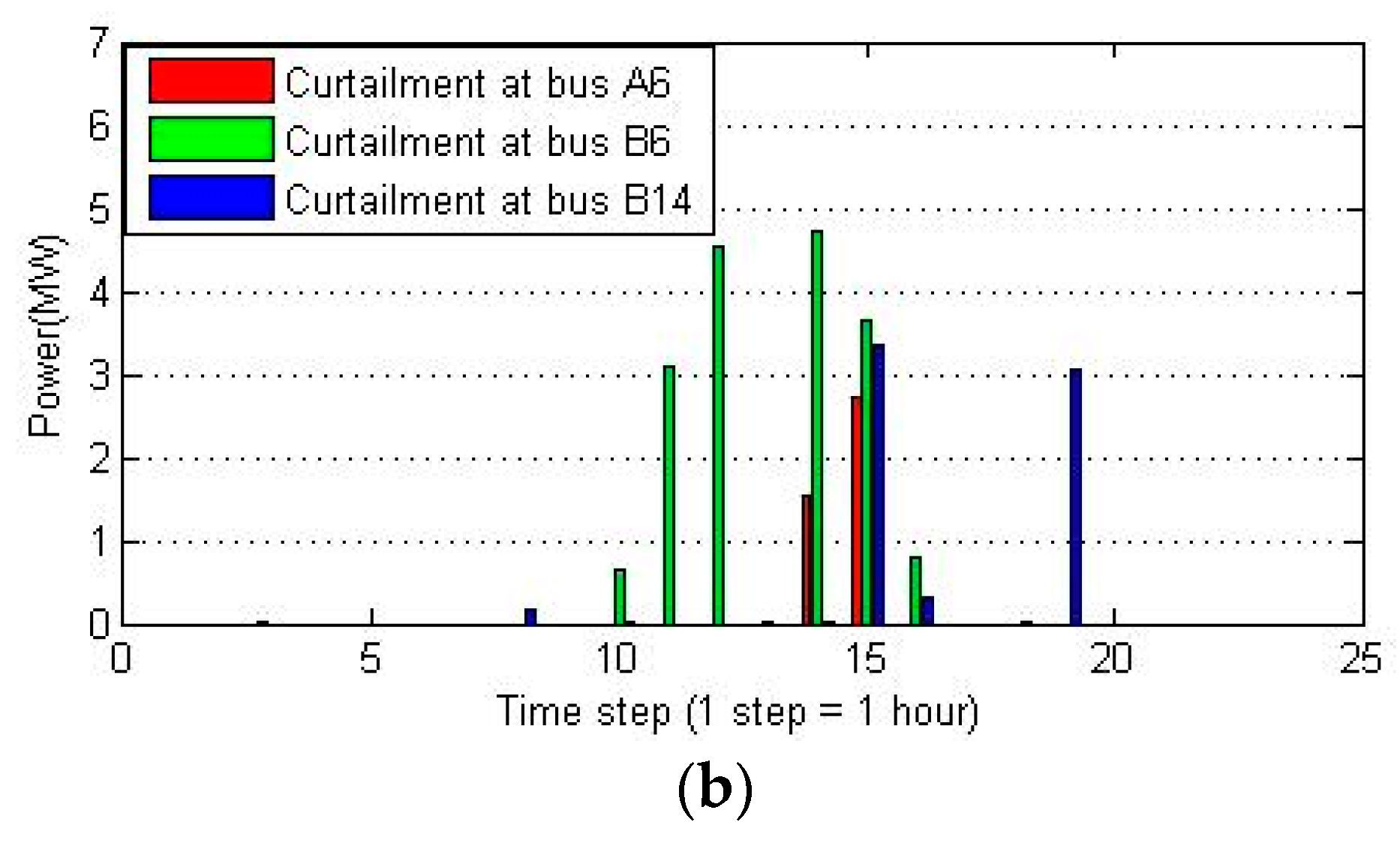
Figure 12.
Simulation results of scenario 3. (a) Flexible demands schedule; (b) renewable generation curtailment.
Figure 12.
Simulation results of scenario 3. (a) Flexible demands schedule; (b) renewable generation curtailment.
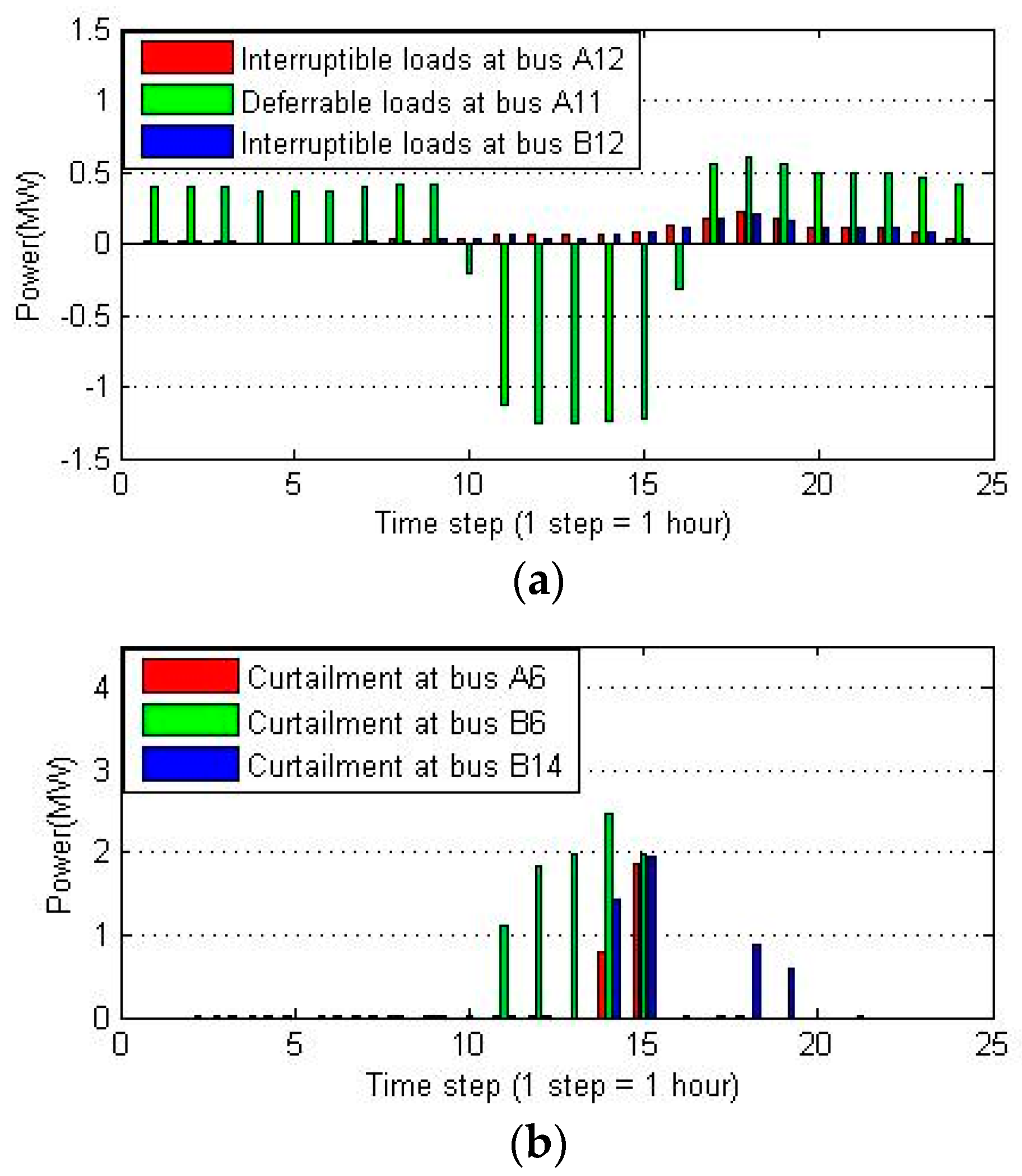
Figure 13.
Simulation results of scenario 4. (a) Active and reactive power of the ACSOP; (b) active power of the DCSOP; (c) renewable generation curtailment.
Figure 13.
Simulation results of scenario 4. (a) Active and reactive power of the ACSOP; (b) active power of the DCSOP; (c) renewable generation curtailment.
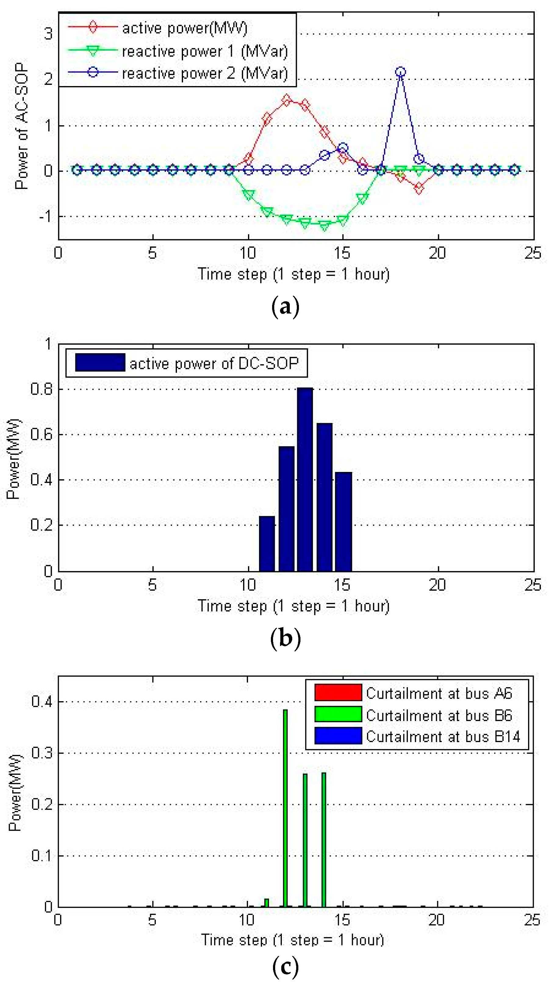
Figure 14.
The distribution network architecture for Case 2.


Table 1.
Control modes of a DC soft open point (DCSOP). (VSC = voltage-source converter).
| Control Mode | VSC1 | VSC2 | Scenario |
|---|---|---|---|
| 1 | PDC control | VACθ control | Normal |
| 2 | VACθ control | PDC control | Normal |
| 3 | VDC control | VACθ control | Network fault at the VSC1 side |
| 4 | VACθ control | VDC control | Network fault at the VSC2 side |
Table 2.
Curtailment at each scenario.
| Scenario | Curtailment | Bus A6 | Bus B6 | Bus B14 | Total (MWh) | Cost ($10,000) |
|---|---|---|---|---|---|---|
| 1 | MWh | 10.8 | 27.3 | 10.1 | 48.2 | 1.98 |
| % | 10.3 | 30.1 | 9.7 | 9.8 | ||
| 2 | MWh | 4.9 | 27.3 | 10.1 | 42.3 | 1.93 |
| % | 4.7 | 30.1 | 9.7 | 8.6 | ||
| 3 | MWh | 4.3 | 17.4 | 6.9 | 28.6 | 1.82 |
| % | 4.1 | 19.2 | 6.7 | 5.8 | ||
| 4 | MWh | 2.7 | 9.4 | 4.8 | 16.9 | 1.72 |
| % | 2.5 | 10.3 | 4.7 | 3.4 | ||
| 5 | MWh | 0 | 0.92 | 0 | 0.92 | 1.51 |
| % | 0 | 1.0 | 0 | 0.19 |
Table 3.
Curtailment and operation cost at each scenario.
| Scenario 1 | Scenario 2 | Scenario 3 | Scenario 4 | Scenario 5 | |
|---|---|---|---|---|---|
| Curtailment (MWh) | 13.52 | 11.96 | 8.49 | 5.32 | 1.53 |
| Cost ($1000) | 6.13 | 6.09 | 5.97 | 5.85 | 5.67 |
© 2018 by the authors. Licensee MDPI, Basel, Switzerland. This article is an open access article distributed under the terms and conditions of the Creative Commons Attribution (CC BY) license (http://creativecommons.org/licenses/by/4.0/).
Share and Cite
MDPI and ACS Style
Zhu, Z.; Liu, D.; Liao, Q.; Tang, F.; Zhang, J.J.; Jiang, H. Optimal Power Scheduling for a Medium Voltage AC/DC Hybrid Distribution Network. Sustainability 2018, 10, 318. https://doi.org/10.3390/su10020318
AMA Style
Zhu Z, Liu D, Liao Q, Tang F, Zhang JJ, Jiang H. Optimal Power Scheduling for a Medium Voltage AC/DC Hybrid Distribution Network. Sustainability. 2018; 10(2):318. https://doi.org/10.3390/su10020318
Chicago/Turabian StyleZhu, Zhenshan, Dichen Liu, Qingfen Liao, Fei Tang, Jun Jason Zhang, and Huaiguang Jiang. 2018. "Optimal Power Scheduling for a Medium Voltage AC/DC Hybrid Distribution Network" Sustainability 10, no. 2: 318. https://doi.org/10.3390/su10020318
Note that from the first issue of 2016, this journal uses article numbers instead of page numbers. See further details here.