Historical Underground Structures as 3D Cadastral Objects


1
Faculty of Mining Surveying and Environmental Engineering, AGH University of Science and Technology, 30-059 Kraków, Poland
2
Institute of Technical Engineering, PWSTE The Bronisław Markiewicz State University of Technology and Economics in Jarosław, 37-500 Jarosław, Poland
3
ProGea 4D sp. z o.o., 31-233 Kraków, Poland
*
Author to whom correspondence should be addressed.
Remote Sens. 2020, 12(10), 1547; https://doi.org/10.3390/rs12101547
Submission received: 17 April 2020
/
Revised: 11 May 2020
/
Accepted: 11 May 2020
/
Published: 13 May 2020
(This article belongs to the Special Issue Remote Sensing and GIS for Environmental Analysis and Cultural Heritage)
Abstract
:The need for accurate registration of underground objects in the 3D cadastre is becoming increasingly common throughout the world. Research studies conducted in this area mostly focus on objects related to transportation or other public utilities and services. However, in settlements with a long history, apart from new objects, there are also various historical objects underground. Such places are not fully discovered, and sometimes they are not even fully inventoried with surveying methods. The aim of this work therefore is to try to describe the possibility of introducing historical undergrounds to the real estate cadastre created for three dimensions, in case of its creation, and to check ground laser scanning as a method of measuring such objects in order to introduce them to the 3D cadastre. Considerations on the inclusion of underground historical objects into the three-dimensional cadastre database began with conceptual considerations. Their result is the elaboration of UML schemas describing relationships among 3D cadastre objects including underground objects. According to the authors, such underground objects should constitute a completely new class called ‘EGB_BuildingBlockUnderground3D’ and be part of the legal space of the entire building represented by the class ‘EGB_BuildingLegalSpace3D’ (the prefix EGB is an acronym of Polish cadastre name ‘Ewidencja Gruntów i Budynków’; in English, it stands for ‘Land and Building Cadastre’). In order to verify in practice the possibility of introducing historical underground objects into the 3D cadastre database, the inventory of the Underground Tourist Route in Rzeszów (Poland) was used. This route consists of a network of underground passageways and cellars built between the 14th and 18th centuries. The measurement was carried out with the application of the Faro Focus 3D terrestrial laser scanner. The underground inventory showed that at the time the current cadastre of land and buildings in Rzeszów was being founded, the boundaries of the cadastral parcels were established without knowing the location of the underground passageways under the Main Market Square. This resulted in a situation in which the objects located underground became parts of more than one cadastral parcel. If a 3D cadastre is created, such a situation must of course be recorded accordingly. The article proposes solutions for such situations.
1. Introduction
The construction of a three-dimensional (3D) cadastre has been discussed around the world since 2001, when a workshop on the topic was held in Delft, the Netherlands [1]. As was later recognised, it was premature to take up this topic due to various organisational, legal, and technological conditions.
Since the beginning of the second decade of the 21st century, a 3D cadastre has become an increasingly popular idea, and this has been determined by two main factors. In 2010, the Joint Commission 3 and 7 Working Group on 3D Cadastres of the International Federation of Surveyors (FIG) was established, and a questionnaire on the future development of the 3D cadastre was prepared, published, and then completed by professionals from various countries. The summary of its results has been described in the work of Oosterom et al. [2]. Since then, similar surveys have twice been developed and completed by representatives from many countries in 2014 [3] and 2018 [4], respectively.
The model for describing registration systems of widely understood space is provided by the ISO 19152 standard ‘Geographic Information—Land Administration Domain Model (LADM)’ [5]. According to ISO 19152, a spatial unit may be a single area (or multiple areas) of land and/or water, or a single volume (or multiple volumes) of space. The 3D spatial unit can be part of space above or below the earth’s surface. Typically, the underground spatial unit refers to the legal space of a building or the legal space of a public utility network. According to the authors, there are no obstacles to proposing the use of ISO 19152 standard mechanisms for the definition of underground objects of cultural heritage, either.
Many research studies concerning the registration of underground objects have been conducted. Very often they concern general issues concerning the 3D cadastre below the earth’s surface, such as registration [6], visualization [7] or dissemination [8]. Research concerning general 3D cadastral issues underground are described by Larsson et al. [9], Adi et al. [10], Jaljolie et al. [11], Radulović et al. [12], and Hicret et al. [13]. They often concern utility networks [14,15,16]. Some of them refer to utilities in the aspects of creating LADM-based schemas [17,18]. There are also some studies that concern underground railways [19,20]. Kitsakis et al. [21] found that many countries around the world have special purpose objects, such as wine cellars and underground buildings. Such research concerning wine cellar registration as an object of a 3D cadastre is described in Janečka and Bobíková [22]. The 3D restrictions resulting from the registration of 3D objects inter alia in connection with cultural heritage objects are described by Kitsakis and Dimopoulou [23].
The issue of the 3D cadastre is inextricably linked with the subject of obtaining data of the objects entered into it. One of the modern and fast methods of obtaining information on object geometry is laser scanning made in LiDAR (Light Detection and Ranging) technology [24]. The scanning can be performed from various platforms: terrestrial (terrestrial laser scanning—TLS), airborne (airborne laser scanning—ALS), mobile (mobile laser scanning—MLS), or satellite (satellite laser scanning—SLS). In addition, in recent years, thanks to the development of technology and the miniaturization of system components, LiDAR scanning from UAVs and mobile components have significantly developed. MLS systems can also be carried by humans, so it can be described as a ‘handy LiDAR’, like ZEB-Revo, ZEB Horizon, or Leica BLK2GO, or a backpack version like ROBIN or Leica Pegasus Backpack.
Bearing in mind the quality of data achieved by measurement systems, for the purposes of obtaining 3D spatial data for cadastral purposes, TLS or MLS instruments can be used. Mobile platforms would be a good solution for large areas in situations where one can move on a dense road network, and close obstacles (buildings, sound absorbing screens) are rare. In the case of densely built-up facilities (cities) where it is not possible to enter everywhere with a mobile platform (e.g., outbuildings of tenement houses) it is necessary to perform TLS scanning. Platforms like ZEB-Revo with a one medium-class scanner currently offer insufficient quality of the data sets, especially in terms of spatial accuracy and the density of final point cloud [25]. On the other hand, the point clouds registered by backpack solutions, e.g., Leica Pegasus or Robin, look much better. Unfortunately, the cost of obtaining such a set is very high in relation to its functionality and performance. Therefore, their number, and hence availability, is small.
Due to the fact that each of the scanning platforms gives a cloud of points with different characteristics, whether in terms of density or coverage of individual surfaces (vertical and horizontal), it seems natural to integrate at least two or more scanning platforms. Examples of such integration can be found in references [26,27,28,29]. Unfortunately, the cost of making two or more scans is usually too high in commercial applications. This leaves us with the application of the most popular scanning systems (TLS), which with appropriate optimization are able to ensure proper measurement accuracy and sufficient representation of reality in the digital world [30].
There is no other measuring technology that is able to obtain so much information about the 3D space that surrounds us in such a short time. During total station measurement, generalization already takes place in the field. The person performing the work decides about the interpretation of the geometry of the object. However, during scanning, the measurement is also performed discreetly, but with much higher density. This allows almost continuous representation of the scanned object. When it comes to data acquisition time, comparable technology is short-range photogrammetry and point cloud generation based on automatic photo-matching [31]. Photogrammetry and laser scanning are not competing technologies, but complementary technologies, examples from different platforms can be found in [32,33,34]. Both, laser scanning and photogrammetry are commonly used in architecture, heritage digitization and documentation [35,36,37,38,39,40].
Undoubtedly, one of the most interesting purposes that can be achieved applying data obtained from TLS or photogrammetric methods is to create virtual models of cultural heritage [41]. Such models are usually created to preserve the historical, architectural and artistic remembrance of these objects, as well as to promote the entire region and the development of tourism there [42]. These issues have already been addressed with the examples of sites located in Canada [43,44,45], Jordan [46], Germany [47], Italy [48,49,50,51,52], Spain [53,54], France [55,56,57], Cyprus [58,59], Ukraine [60], Slovakia [61], and Poland [62,63,64].
However, the greatest challenge is to describe the underground structures that were not inventoried before they were buried in the ground. This is particularly important in situations where we would like to have the geometrical description of these objects to be as accurate as possible, which could then be used to introduce them into a 3D cadastre in the future. The purpose of this paper therefore is to describe the works that have been carried out in order to investigate the possibility of including historical underground objects in a 3D cadastre.
2. Materials and Methods
2.1. Research Methodology
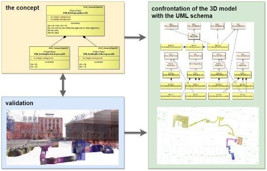
The research was conducted in three stages: conception, validation, and confrontation. As is clear from the research methodology presented in Figure 1, the first two stages can be carried out in parallel and completely separately. They meet at stage three.
The conceptual stage began with an analysis of selected elements of the Polish real estate cadastre as well as Polish and worldwide literature. The aim of this analysis was to confront the existing provisions of Polish law, which concern two dimensions, with the proposals of 3D cadastre models described in the literature. Due to the numerous historical underground objects that can be found in many cities, one of the research goals was to create the possibility of including these structures in the existing 3D cadastre models.
The analysis of the literature focused on the search for information that could help formulate assumptions for further consideration and to propose a UML scheme covering historical objects located under the surface of the earth. New classes were proposed for these objects, and for selected classes attribute lists were created.
The validation stage included the inventory measurement of an example of historical underground structures. The data obtained was used to create a three-dimensional model of the object. Having a 3D model of the underground structures, we checked whether the data obtained during the inventory was sufficient to enter the measured object into the 3D cadastre database created in accordance with the proposed scheme.
2.2. Research Object
The explored site was a complex of former cellars, located in the city of Rzeszów in south-eastern Poland (Figure 2), under the Main Market Square (Figure 3 and Figure 4).
The city of Rzeszów was selected as it is a historical city, whose development toward a ‘smart city’ has resulted in a continuous increase in the number of surveying works performed there [66]. According to the authors, such a fact could facilitate the implementation of the 3D cadastre there in the future.
Rzeszów, as a medium-sized city, is ranked 20th in Poland, both in terms of population and area. It is located in the south-east of Poland, i.e., in an area with a fragmented structure of registered land parcels and a high population density. Important characteristics of Rzeszów, the Podkarpackie province, and Poland are presented in Table 1.
Rzeszów is a city with a long history, thanks to which the selected underground sites were created (Figure 5).
After Rzeszów was incorporated into the Habsburg Monarchy (later the Austrian Empire) in 1772, the area of the city was covered by the Austrian cadastre, which did not include any underground structures. Many cartographic studies have survived from that period. They were used as a model for establishing Poland’s current real estate cadastre (Figure 6).
The Underground Tourist Route in its present state has been operating since 2007. It consists of objects which were built from the 14th to the 18th centuries. It leads under the Main Market Square and five neighbouring houses. The route is about 400 metres long and consists of 40 interconnected rooms (15 passageways and 25 cellars). They are located between 0.5 m and 10 m below the surface of the Main Market Square.
The objects making up the route are not recorded in the current cadastre, for such objects are not registered there. The Underground Tourist Route is located under eight land parcels, of which five are built on (Figure 7).
2.3. Methodology of Measurement
The validation of the proposed UML scheme was carried out based on an inventory measurement, which was performed using terrestrial laser scanning (TLS).
By performing terrestrial laser scanning, it is possible to obtain single millimetre accuracy, with a data acquisition rate of around 1 million points per second. The specific values depend on the scanner model used. In the measuring range from 0.6 m to 50 m, the accuracy of linear distance is between less than 1 mm (Z + F Imager 5006/5010/5016, Trimble TX8) and 6 mm (GeoMax SPS Zoom 300, Stonex X300). A point cloud from each station is acquired in the local coordinate system. At the post-processing stage, all positions should be registered to one coherent coordinate system for the entire project. There are several methods for the registration of separate scans in the entire project. The most popular methods are target-based registration, cloud-to-cloud, and feature-based registration [67].
Methods based on signalled targets (target-based registration; checkerboards, spheres) are accurate but require time for the proper placement of measurement marks. The fieldwork is quicker for cloud-to-cloud registration and feature-based registration. Regarding the processing stage, the target-based method requires more time to check the checkerboards and/or spheres, while cloud-to-cloud and feature-based registration requires better hardware and less operator intervention. It is important to know which way will be chosen to get the final registration because different methods of registration require different locations of scan position and/or targets.
As for the accuracy that can be achieved, registration methods are similar to each other. Characteristics of the object and the shape of the measurement network have the greatest impact. Sometimes georeferencing can be carried out, that is, to transform point clouds from a project coordinates system to a national/global coordinates system.
Regardless of the software used, several stages can be distinguished in the TLS data processing process. The whole process begins with importing data obtained by the instrument. In most cases, these are the manufacturer’s own files; therefore, previewing the content at this stage is difficult. Most scanner manufacturers have dedicated software for their scanners. In most cases, it is not possible to import data from other scanners, but this software is able to use the maximum information collected during the measurement—e.g., RiSCAN PRO from Riegl. However, using universal software (e.g., Trimble Real Works), we are able to process data from scanners of several manufacturers, which in addition to ease of use translates into lower costs. The second main step is to search for automatic targets. They can be either spheres of a defined size or black and white chessboards. Both spheres and chessboards have their production advantages; therefore, it seems logical to use both signals, depending on the characteristics of the object, the availability of signals, and the measurement schedule. After the automatic target search stage, there is a manual correction of the previous process. It is about checking if all the objects found by the algorithm are really marked by the measuring team. It very often happens that the centres of targets are found on the floors of historical buildings (churches, palaces) as long as the individual elements of the floor have contrasting colours (light/dark). Another example of frequent errors are the spheres located in treetops or fitted into the shades of streetlamps. These are objects that the program finds redundant. The second type of error occurs when the actual signals were not recognized automatically. Then you have to add them manually. With a proven target database, you can start the project registration process. Alignment based on signalled targets takes place in an iterative manner, during which the operator decides whether or not to use specific connections between targets. This process continues until the desired global alignment parameters are reached. Usually, the quality of the assembly is assessed by providing the average error (difference between the target centres) and the maximum value among these differences.
The stage of colouring the cloud of points on the basis of the oriented photos obtained during the measurement can be performed at different times of LiDAR data processing. It depends mainly on the software used. In Faro Scene, it is best to perform cloud colouring after the project registration stage. In RiSCAN PRO, colouring can be done at any time, but it is a separate process. In Trimble RealWorks, on the other hand, colouring is already done when importing native files from the scanner. The last step is exporting point clouds to the selected format—most often it is the LAS or LAZ format. In addition to its universality (LAS files are read by 99% of the software), the advantage of the LAS/LAZ formats is that the file size is reduced without losing information. As shown in the summary, LAS files are 2–3 times and LAZ files up to 10 times smaller than ASCII files [68]. Research on compression options has been conducted for many years [69] because the volume of the final point clouds is of great practical importance. The next step that may occur is to clean the LiDAR dataset from error points (noise). This step is optional, depending on the project requirements. The last processing step, and also the first step toward modelling, is cutting the whole point cloud into blocks. They allow you to load fragments of the point cloud and perform measurements/modelling without overloading the computer’s memory.
The final stage is the modelling based on the LiDAR point cloud. For this purpose, you can use any CAD type software that has the ability to load point clouds (Bentley MicroStation, Autodesk AutoCAD). The resulting model can be a set of lines in 3D, surfaces or solids. Based on LiDAR data, you can also prepare a building information modelling (BIM) model that, in addition to geometric representation, will contain descriptive elements—an infinite number of attributes for all model elements.
The survey used to validate the conceptual research was also used to create a virtual walk through the historic underground of the Main Market Square in Rzeszów [70]. The carried-out survey referred to the state geodetic framework. It covers the interior of the whole object (Figure 8).
The data acquisition was made with a Faro Focus 3D scanner. In total, 88 scans were carried out, including 71 in the underground part and 17 in the ground part, obtaining 1.4 billion points (956 million in the underground and 444 million in the ground part). The scans were registered using the cloud-to-cloud registration method. Post processing was carried out using RiSCAN PRO 2.8 software, obtaining a standard deviation of about 2.9 mm for the whole project.
To make a georeferencing for the final point cloud, four points measured by GNSS RTN were used. Coordinates of GNSS points were in PL-2000_7 (EPSG:2178) and PL-KRON86-NH [71,72]. The LiDAR project was fitted applying the least square method into GNSS coordinates with an obtained standard deviation of 4.5 cm.
3. Toward a UML Model for Underground Structures
3.1. The Cadastral System in Poland
In the case of Poland, where the research area is located, information on real estate is collected and managed within two systems [73] (based on Law on Geodesy and Cartography [74] and Act on Land Register and Mortgage [75]). They are the land and building cadastre as well as the land and mortgage register.
A cadastre is a system for registering land (including properties) and rights to it. The location of land or property and the associated attributes are registered within the cadastral system. Cadastral objects in Poland are land parcels and buildings or premises (apartment units) that are separately owned estates. A traditional cadastre is a system where the information basically concerns two dimensions and reference to the three-dimensional reality is realized, for example, by attributes such as the number of aboveground or underground storeys. The cadastral model itself and its graphic representation are basically limited to dimensions X and Y. Cadastral data mainly consists of spatial descriptions, attributes, values, and the corresponding official documents. The bases of the cadastre in Poland are defined by geodetic and cartographic law [74]. Details regulating the contents and operations of the cadastre are defined by the Regulation of the Ministry of Regional Development and Buildings [76].
The conceptual model of Polish cadastral data is defined within the Regulation from 29 November 2013 [77]. It consists of UML application schema, a catalogue of objects, and geographic mark-up language (GML) application schema [78]. The catalogue of objects contains definitions and descriptions of the types of objects presented in the application model, and their attributes and interrelations between them, occurring in one or more diagrams. The Polish cadastral model consists of 71 classes grouped in eight thematic packages and applied in 16 diagrams [73] (based on Regulation changing the Regulation on Land and Building Cadastre [77]).
3.2. Cadastral Developments in Poland
Since 2010, ideas about a 3D cadastre have gained widespread popularity in Poland. In 2010, a questionnaire on a 3D cadastre for Poland was completed within the activities of the FIG Joint Commission 3 and 7 Working Group on 3D Cadastres [79]. As a result of this popularity, research studies concerning 3D cadastre issues have commenced in various academic centres in Poland. They are either based on practical examples, are theoretical models, or are a combination of both. A short review of cadastral works in Poland is described briefly below.
A model of a 3D+time cadastre is proposed in Siejka et al. [80]. The transition method from a 2D cadastre to a 3D cadastre (including the time factor) is described therein. The UML simplified models for a real property register, a land and building cadastre, the spatial registration of utility infrastructure, and a 3D+time cadastre are also presented in that paper.
The possibility of applying the digital elevation model (DEM) to the creation of a 3D cadastre in the example of large areas is studied in Sanecki et al. [81]. According to that study, the digital elevation model obtained from the application of LIDAR technology may be used for the creation of a 3D cadastre if the proper technological and precision criteria are met. The model approach to a 3D cadastre, enabling the registration of rights in layers (strata) in Poland is proposed in Karabin [82] and Karabin [83].
The application of CityGML for 3D representations of buildings is described by Góźdź et al. [84]. Based on practical examples obtained from airborne laser scanning and applying CityGML, the 3D representations of building legal spaces are proposed therein.
The cadastral concept based on the 3D-LADM country profile development for Poland is proposed by Góźdź and Pachelski [85]. Land Administration Domain Model packages are applied, and new 3D objects like PL_3DParcel, PL_RestrictedParcel, or PL_UnrestrictedParcel are implemented. Felcenloben [86] suggests the introduction of spatial real estate that should enable ownership rights to be established in the Polish legal system for objects built above or under the surface of the land.
The expansion of the cadastral system functionality for the new 3D objects was proposed in Bydłosz et al. [87] and Bydłosz [88]. The three-dimensional parcels are represented by EGB_CadastralParcel3D and EGB_BuildingLegalSpace3D classes. According to this model, 3D parcels can be situated above the ground, under the ground, or be a combination of both. The introduction of 3D cadastre classes into the Polish cadastral model is described in Bydłosz [89]. The classes representing the proposed 3D cadastral objects are implemented to the Polish cadastral model defined earlier in legal regulations [90]. The model comprises of original cadastral classes [89], 3D cadastral objects added in earlier research works [87,88,89], and classes representing spatial planning objects. The relationships among them are described in Bydłosz et al. [91].
There are also some studies where the 3D cadastre is analysed in the context of possibilities [92] and possible obstacles [93] of its establishment in Poland. In the authors’ opinion, all the developments of the 3D cadastre should uphold the application of good governance [94] and take place within the trends of global cadastral development [95].
3.3. Important 3D Issues and Background
In the real world, a parcel is a three-dimensional object that is part of the earth’s surface. Restrictions on the use of land parcels are based on the provisions of the Civil Code [96] as well as other legal acts such as Aviation Law [97] or Geological and Mining Law [98]. A land parcel may be built on ‘vertically’ both upward and downward, provided that it complies with the law and if appropriate permits are obtained. For example, you can move around a land parcel or erect buildings on it (upward use). Similarly, one can also, e.g., dig holes or wells (downward use). It follows that a registered parcel is actually a solid with boundaries not fully defined in vertical space.
It can be assumed that the determination of the ownership or use of a property in space can be treated differently depending on whether it is an ‘upward’ or ‘downward’ case. It seems that, in the first case, the previously mentioned provisions of the Civil Code and the Aviation Law regulate these issues quite well, although they are not always able to prevent the emergence of disputed situations. Perhaps it results from the fact that we can see the space above the ground. Nevertheless, this case is not the subject of the described research.
The second case—the range of rights related to a property used ‘downward’—seems to be much more complicated. Perhaps the reason is that we generally do not see what is under the surface of the ground or, being underground, we see certain parts of the underground structure without seeing the surface itself. There are limitations resulting from the Geological and Mining Law [98], as well, according to which all mineral resources belong to the State Treasury.
In airspace, we are able to move or register objects applying technical means, but free movement inside the Earth’s crust is not possible. All kinds of construction projects are easier and cheaper to carry out above the Earth’s surface than under it. Therefore, it seems that the issue of the range of rights to property above and below the Earth’s surface should be treated separately. In this paper, we will deal with the problems of registering objects under the surface of the Earth.
The scope of ‘downward’ rights in Polish law, in addition to the already mentioned Civil Code defining a certain general legal framework, results from the provisions of the Construction Law [99] and construction permits issued on its basis. As pointed out in references [19,100,101,102], the aboveground and underground parts of a space often belong to different owners, and when a given property has an aboveground and underground part their vertical projections often do not coincide. For facilities built relatively recently on the basis of the legal acts cited above, there are usually no grounds for potential claims to extend the right of ownership ‘down’. The situation is different when the underground object was built much earlier. Therefore, the authors decided to use a model where, if necessary, the underground and aboveground objects can be considered separately.
3.4. Modelling Relationships between Underground and Aboveground Objects in UML
The model referred to above is based on the UML cadastre model described in [89], where classes EGB_BuildingLegalSpace3D, EGB_BuildingBlockUnderground3D, and EGB_BuildingBlockAboveground3D were proposed for the description of the three-dimensional legal space of a building (Figure 9).
The model is quite simple and is restricted to the space of the aboveground or underground part of the building and limited by vertical planes. As can be seen in the examined case, it is insufficient. During the modification and development of the UML model for EGB_BuildingLegalSpace3D, it was decided to replace the condition
as it was too restrictive and did not reflect the actual state, with a simple relation (2), where the total volume is equal to the sum of the volumes of both the underground and aboveground parts. It was also decided to introduce attributes Vu and Va (underground or aboveground measured volumes) correspondingly for classes EGB_BuildingBlockUnderground3D and EGB_BuildingBlockAboveground3D.
Hu × Au + Ha × Aa = V,
V = Vu + Va.
The attribute V (volume of the whole object) is delivered only when both Vu and Va are provided.
In the 3D cadastre model presented in [89], class EGB_BuildingLegalSpace3D is connected by the direct link to the EGB_Building class. The same relationships between the classes EGB_BuildingBlockUnderground3D, EGB_BuildingBlockAboveground3D, and the class EGB_BuildingBlock have been added. This is presented in Figure 10.
The situation is more complicated in the case of underground historical objects, as is shown in the analysed case. The surveyed underground sites were built between the 14th and 18th centuries. At that time, unlike today, issues related to the range of rights in vertical space were not considered. The result of this is that interconnected underground objects pass under several cadastral parcels (Figure 7), and access to them is possible from several different properties. This raises the problem of assigning individual parts of the underground objects to specific properties.
Hence the new proposal of classification of underground objects in relation to buildings and parcels is as follows:
As the analysed properties consist of buildings, based on rules given in Sanecki et al. [81] and later developed in the paper, their examples are represented in UML schemas by the instances of class EGB_BuildingLegalSpace3D. Correspondingly, aboveground and underground objects are represented by instances of classes EGB_BuildingBlockAboveground3D and EGB_BuildingBlockUnderground3D.
In case no. 1 (Figure 11), it is proposed that both aboveground and underground objects should belong to the one property, although in the vertical plan the underground object may be located under various land parcels. The UML schema presenting this case is shown in Figure 12.
If the underground part of the object can be accessed from two or more buildings (case 2), the following four options seem possible:
In case 2a (Figure 13a), either the underground part should be treated as a separate object or the underground part should be divided and the functionality criterion (description below) applied. The UML schemas of corresponding instances are presented in Figure 14 and Figure 15.
In case 2b (Figure 13b), the underground object should be the subject of division. It may be made with one of two methods. In the first method, the vertical boundary faces, dividing the underground object, are constructed based on the land parcel boundaries on the surface. The second method is based on the functionality criterion. It means that if some parts of the underground object are functionally integral with the building, then they should belong to the appropriate real property. The instance of this case in the UML schema is presented in Figure 16.
In case 2c (Figure 13c), the underground object should be divided between two real properties having access to it. The functional integrity criterion (as in cases 2a and 2b) should be used here. The corresponding schema is presented in Figure 17.
In case 2d (Figure 13d), similar rules as in case 2b should be applied. In this case, the underground object is divided among properties having access to it. It is presented in Figure 18.
Each object belonging to the class EGB_BuildingBlockUnderground3D must naturally be described with attributes. Most of them will be similar to those of the aboveground objects. However, due to the specificity of underground objects, it is suggested to save information about their geometry in the 3D cadastre database. The proposed attributes are presented in Table 2.
The ‘contour type’ attribute determines which solid we are dealing with. It means whether the object entered into the 3D cadastre database was created on the basis of data concerning the internal walls of the underground object, and thus the block of the building fills its centre, or whether this object represents the external walls of the object.
Since contour measurements (whether external or internal) can be obtained in various ways, it is proposed to distinguish the ‘contour source’ for EGB_BuildingBlockUnderground3D objects. Direct measurement of the external contour would be most desirable. However, this would be possible only in the case of excavation made when creating new underground objects or in the case of the excavation of historical buildings during archaeological and conservation works. In practice, new underground objects are often created as a result of tunnelling. Underground historical objects, however, are very often only explored and renovated from the inside. Therefore, the most probable possibility seems to be entering data from the interior direct measurement into the 3D cadastre database. The geometry of the external contour can then be additionally collected from construction documentation (rather for new objects, but also for historical objects, for which relevant materials in the archives have been preserved) or with the use of additional equipment, such as a geo-radar, which will enable the detection of wall thickness from the inside of the object.
Due to the variety of measurement methods that can be used to determine the geometry of underground objects, it is additionally proposed to introduce information on the error of this measurement into the 3D cadastre base. This error should be determined in relation to the state geodetic network used for the measurement, therefore this attribute is called ‘positioning error in relation to the control network’.
Such an attribute is already functioning in the Polish cadastre and concerns the boundary points of registered parcels. Its range derives from the Polish legal regulations [76]. The accuracy of boundaries in the Polish real estate cadastre is determined by the average error of the border point location. This error is related to the basic first class geodetic control network [103]. The lowest values are obviously related to direct measurements. Higher values should be expected when the contour is determined using wall thickness detection equipment or archival documentation. Certainly, the greater the measurement error, the greater the margin of safety around the underground objects will have to be maintained by the designers engaging in the underground space in which these objects are located [104].
4. Results and Discussion
4.1. D Model of the Underground Tourist Route
Due to the variety of measurement methods that can be used to determine the geometry of underground objects, it is additionally proposed to introduce information on the error of this measurement into the 3D cadastre base. This error should be determined in relation to the state geodetic network which was used for the measurement; therefore, this attribute is called ‘positioning error in relation to the control network’.
The final point cloud in LAS format was loaded into Bentley MicroStation Connect Edition using the TerraScan point cloud MDL application (Figure 19).
The set of software (MicroStation + TerraScan) allows the use of extensive modelling tools contained in Bentley software and advanced functions for handling and processing point clouds created by TerraSolid. Thanks to TerraScan tools, the modelling process was efficient and accurate. Due to the fact that the cloud of points for the underground route in most cases covered only the inside of the route, it was decided to make a model in the form of a surface.
Only objects which had information on all their dimensions from the point cloud were modelled as a solid. Due to the technology (LiDAR) used, it was not possible to obtain information on the thickness of the walls of individual passageways. The effect of the modelling was to rearrange the entire underground route in the form of surface models in the DGN file (Figure 20).
Models of buildings surrounding the Main Market Square were created by pulling outlines of buildings taken from land and building cadastre above and below the Main Market Square (Figure 21). The height of the building’s extension was determined on the basis of a point cloud - the height of the body is consistent with the height of the front wall. The parcel borders were extruded 10 m above and 10 m below surface of the Main Market Square to visualise property rights.
4.2. UML Schema for the Underground Tourist Route in Rzeszów
As mentioned earlier, the Underground Tourist Route is located under eight land parcels. Their detailed characteristics are presented in Table 3.
Most of the land parcels under which the Underground Tourist Route is located belong to the Municipality of Rzeszów. However, there are also parcels (991/2 and 992) that are privately co-owned by three individuals and one legal entity. Only three of the parcels belonging to the city are not built-up (985/2, 986/2, and 988). It is on these parcels that the Main Market Square in Rzeszow was arranged. On the developed parcels, there are office buildings used by the City Authority (1001 and 1002/1) and a cultural institution building (986/1). The management of the 986/1 parcel is held by a legal entity, which also manages the entire Underground Tourist Route.
The Route is physically connected with three buildings, located on parcels 986/1, 992, and 1001. The entrance to the Route is located in a building located on parcel 986/1. The exit is located outside the office building on parcel 1001—exiting the Route, you cannot enter the building. However, the direct passage between the building and the Route is still on parcel 992. It is located underground, because not all the cellars underneath the hotel have been included in the Underground Tourist Route. The hotel restaurant is located in the cellars separated from the Route.
Based on the criteria and analysis described in Section 3.4, the UML schema of the Underground Tourist Route was prepared. It is presented in Figure 22. The schema comprises both instances of 3D objects (EGB_BuildingBlockUnderground3D, EGB_BuildingBlockAboveground3D, and EGB_BuildingLegalSpace3D) as well as objects deriving from the Polish cadastral model (EGB_CadastralParcel, EGB_Building. and EGB_BuildingBlock). Instances of class EGB_BuildingBlockUnderground3D are also parts of corresponding buildings and legal spaces represented by instances of class EGB_BuildingLegalSpace3D, with numbers deriving from the parcel (and subsequently building) ID.
The measured Underground Tourist Route meets the criteria of the case shown in Figure 13d (access to an underground object from more than two properties). The exact relationship between the objects making up the Underground Tourist Route and the related objects are shown in Figure 22.
All instances of class EGB_BuildingBlockUnderground3D make the object UndergroundTouristRoute:EGB_BuildingBlockUnderground3D, which is the UML representation of the whole Underground Tourist Route (Figure 23).
As can be seen in the diagram (Figure 23), the Underground Tourist Route is composed of underground building blocks marked as 986/1;1;2, 992;1;2, 1001;1;2, and 1001;1;3. During the establishment of the land cadastre, the configuration of the boundaries of the cadastral parcels was determined without the knowledge of the location of the passageways forming the Route, so these blocks are very often situated below more than one cadastral parcel. That is why, when describing the Underground Tourist Route with the UML schemas, the following two assumptions were made:
- the blocks forming passageways running under non-built-up parcels are included in the legal space of the buildings from which there is an entrance to these passageways;
- the boundaries between the underground blocks were established along the existing cadastral boundaries.
On the basis of these assumptions, the following division of the Underground Tourist Route has been adopted as presented in Figure 24:
- block 986/1;1;2 (located under parcels 985/2, 986/1, 986/2, and 988) was associated with a building located on parcel 992/1 (marked in yellow in Figure 24);
- block 992;1;2 (located under parcels 991/2 and 992) was associated with a building on parcel 992 (marked in orange in Figure 24);
- block 1001;1;3 (located under parcel 988) was associated with a building located on parcel 1001 (marked in magenta in Figure 24);
- block 1001;1;2 (located under parcels 1001 and 1002/1) was associated with a building located on parcel 1001 (marked in blue in Figure 24).
No separate blocks have been created for the underground part of the building located on parcel 986/1, and the passageways under parcels 985/2, 986/2, and 988, as the functionality criterion explained in Section 3.4 was applied here. We decided to take this approach because the underground wall of the building does not coincide vertically with the parcel boundary, so the passageway starts below parcel 986/1. In other cases, the underground blocks were separated along the cadastral borders coinciding with the ground floor of the building registered in the cadastre. The underground objects forming the Route are presented in Figure 24.
Due to the clarity of the drawings containing UML schemas for the Underground Tourist Route, the attributes of objects forming this Route are not shown. However, it should not be forgotten that the underground blocks should be characterized by the previously proposed attributes. The whole underground part of the Route was measured directly, but only inside, with accuracy below 5 cm. We propose adding the following attributes to all building blocks:
- contour type;
- contour type source: measurement of interior;
- positioning error in relation to the control points 0–0.10 m.
5. Recapitulation and Conclusions
It is very difficult to introduce objects that were created underground many years ago (before buildings were being officially registered) into the cadastre. At the time when the current land and building cadastre was established in Rzeszów, the boundaries were probably established without knowing the precise location of the passageways under the Main Market Square. This resulted in a situation in which the underground buildings became part of more than one registration parcel. Even if these parcels now form part of one registration unit, this may change in the future. Assuming that the building (here underground) is part of the parcel and is located within it, it is not possible to introduce the existing historical underground part of the Main Market Square in Rzeszów to the 3D cadastre. This is because it is difficult to recommend dividing the network of underground passageways with planes running along the registration boundaries. It seems that the passageways underneath the Main Market Square should rather be treated as one object. In this case, the 3D cadastre database created a relation of one underground block ‘EGB_BuildingBlockUnderground3D’ overlapping with ‘EGB_BuildingLegalSpace3D’, with many parcels. The only exception should be the cellars underneath the buildings, which should be entered into the database as part of ‘EGB_BuildingLegalSpace3D’.
It is important to remember that recording historical structures in a 3D cadastre is extremely difficult. The description of a selected research object, which is the Underground Tourist Route located under the Main Market Square in Rzeszów (south-eastern Poland), using the UML schema, has caused considerable difficulties. It is not possible to pass from these underground parts to the two buildings under which they are situated (on parcels 991/2 and 1002/1). Therefore, it was proposed to include parts of the Route located underneath these buildings in the legal spaces of the neighbouring buildings, with their cellars directly connected.
Thus, the Underground Tourist Route was divided into four separate underground blocks. The first one includes the underground part of the building located under land parcel 986/1 and a passageway connected with the building, running under the Main Market Square up to the border, which in a vertical projection coincides with its eastern facade. The first one includes the underground part of the building located under land parcel 986/1 and a passageway connected with the building, running under the Main Market Square up to the border, which in a vertical projection coincides with its eastern facade. The second one consists of cellars included in the Route, located under the buildings located on parcels 991/2 and 992. The third block is a passageway under the south-eastern corner of the Main Market Square. The fourth block consists of cellars under the buildings on parcels 1001 and 1002/1.
The adopted methods of measuring the Underground Tourist Route in Rzeszów let basically to invent historical underground objects from the inside. The thickness of the walls of underground objects is not specified. According to the authors, their assessment requires additional research taking into account various methods, e.g., ground penetrating radar. At present, it seems that further works could also focus on the measurement of surface objects. In the area of UML modelling further research is needed to determine the relationships among surface objects, i.e., the land parcels, buildings, and building legal spaces. It is also worth noting that, as in this study, any further work should be conducted taking into account the best practices in the 3D cadastres [105].
Author Contributions
Conceptualization, A.B. and J.B.; Methodology, A.B.; Data collection and processing, M.B. and A.W.; Data validation, A.W.; Investigation, M.B., A.B., J.B., and A.W.; Literature surveys, M.B. and J.B.; Supervision, A.B.; Visualization, M.B., A.B., J.B., and A.W.; Writing—original draft, M.B., A.B., J.B., and A.W.; Writing—review and editing, A.B. All authors have read and agreed to the published version of the manuscript.
Funding
This research received no external funding.
Acknowledgments
This work was prepared within the scope of the research funds from the AGH University of Science and Technology in Krakow and PWSTE, the Bronisław Markiewicz State University of Technology and Economics in Jarosław. The authors express their words of gratitude to ProGea 4D for the equipment and software that we applied in data post-processing.
Conflicts of Interest
The authors declare no conflict of interest.
References
- FIG joint commission 3 and 7 Working Group on 3D Cadastres. In Proceedings of the International Workshop on “3D Cadastres”, Delft, The Netherlands, 28–30 November 2001; Available online: www.gdmc.nl/3DCadastres/workshop2001/ (accessed on 23 March 2020).
- Oosterom, P.; Stoter, J.; Ploeger, H.; Thompson, R.; Karki, S. World-wide inventory of the status of 3D Cadastres in 2010 and expectations for 2014. In Proceedings of the FIG Working Week, Bridging the Gap between Cultures, Marrakech, Morocco, 18–22 May 2011. [Google Scholar]
- Oosterom, P.; Stoter, J.; Ploeger, H.; Lemmen, C.; Thompson, R.; Karki, S. Initial Analysis of the Second FIG 3D Cadastres Questionnaire: Status in 2014 and Expectations for 2018. In Proceedings of the 4th International Workshop on 3D Cadastres, Dubai, United Arab Emirates, 9–11 November 2014. [Google Scholar]
- Oosterom, P.; Shnaidman, A.; Rahman, A.A.; Karki, S.; Lemmen, C.; Ploeger, H. Analysis of the Third FIG 3D Cadastres Questionnaire: Status in 2018 and Expectations for 2022. In Proceedings of the FIG Working Week 2019, Geospatial information for a smarter life and environmental resilience, Hanoi, Vietnam, 22–26 April 2019. [Google Scholar]
- ISO. Geographic Information–Land Administration Domain Model (LADM); International Organization for Standardization: Geneva, Switzerland, 2012; ISO 19152:2012. [Google Scholar]
- Dimopoulou, E.; Karki, S.; Roić, M.; De Almeida, J.; Griffith-Charles, C.; Thompson, R.; Ying, S.; Paasch, J.; van Oosterom, P. 3D Cadastres Best Practices, Initial Registration of 3D Parcels. In Proceedings of the FIG Congress, Istanbul, Turkey, 6–11 May 2018. [Google Scholar]
- Cemellini, B.; Thompson, R.; de Vries, M.; van Oosterom, P. Visualization/Dissemination of 3D Cadastre. In Proceedings of the FIG Congress, Istanbul, Turkey, 6–11 May 2018. [Google Scholar]
- Thompson, R.; van Oosterom, P.; Cemellini, B.; de Vries, M. Developing an LADM Compliant Dissemination and Visualization System for 3D Spatial Units. In Proceedings of the 7th Land Administration Domain Model Workshop, Zagreb, Croatia, 11–13 April 2018; pp. 103–124. [Google Scholar]
- Larsson, L.; Paasch, J.; Paulsson, J. Conversion of 2D Analogue Cadastral Boundary Plans into 3D Digital Information—Problems and Challenges Illustrated by A Swedish Case. In Proceedings of the 6th International Workshop on 3D Cadastres, Delft, The Netherlands, 2–4 October 2018; pp. 75–94. [Google Scholar]
- Adi, R.; Shnaidman, A.; Barazani, S. Implementation of the 3D Cadastre in Israel. In Proceedings of the 6th International Workshop on 3D Cadastres, Delft, The Netherlands, 2–4 October 2018; pp. 155–176. [Google Scholar]
- Jaljolie, R.; van Oosterom, P.; Dalyot, S. Spatial Data Structure and Functionalities for 3D Land Management System Implementation: Israel Case Study. ISPRS Int. J. Geo Inf. 2018, 7, 10. [Google Scholar] [CrossRef] [Green Version]
- Radulović, A.; Sladić, D.; Govedarica, M. Towards 3D Cadastre In Serbia: Development of Serbian Cadastral Domain Model. ISPRS Int. J. Geo Inf. 2017, 6, 312. [Google Scholar] [CrossRef] [Green Version]
- Gursoy Surmeneli, H.; Alkan, M. Design and Determine 3D Cadastral Systems: A Case Study of Turkey. In Proceedings of the 6th International Workshop on 3D Cadastres, Delft, The Netherlands, 2–4 October 2018. [Google Scholar]
- Pouliot, J.; Girard, P. Subsurface Utility Network Registration and the Publication of Real Rights: Towards Full 3D Cadastre. Recovery from Disaster. In Proceedings of the FIG Working Week 2016, Christchurch, New Zealand, 2–6 May 2016; pp. 1–9. Available online: http://www.gdmc.nl/3dcadastres/literature/3Dcad_2016_01.pdf (accessed on 12 May 2020).
- Pouliot, J.; Girard, P. 3D Cadastre: With or without Subsurface Utility Network? In Proceedings of the 5th International Workshop on 3D Cadastres, Athens, Greece, 18–20 October 2016; pp. 47–59. [Google Scholar]
- Yan, J.; Jaw, S.W.; van Son, R.; Soon, K.H.; Schrotter, G. Three-Dimensional Data Modelling for Underground Utility Network Mapping. Int. Arch. Photogramm. Remote Sens. Spat. Inf. Sci. 2018, XLII-4, 711–715. [Google Scholar] [CrossRef] [Green Version]
- Kim, S.; Heo, J. Development of 3D underground cadastral data model in Korea: Based on land administration domain model. Land Use Policy 2017, 60, 123–138. [Google Scholar] [CrossRef]
- Radulović, A.; Sladić, D.; Govedarica, M.; Ristić, A.; Jovanović, D. Towards 3D Utility Network Cadastre: Extended Serbian LADM Country Profile. In Proceedings of the 6th International FIG 3D Cadastre Workshop, Delft, The Netherlands, 2–4 October 2018; pp. 95–110. [Google Scholar]
- Karabin, M.; Kitsakis, D.; Koeva, M.; Navratil, G.; Paasch, J.; Paulsson, J.; Vučić, N.; Janečka, K.; Lisec, A. Layer Approach to Ownership in 3D Cadastre—A Subway Case. In Proceedings of the 6th International Workshop on 3D Cadastres, Delft, The Netherlands, 2–4 October 2018; pp. 111–136. [Google Scholar]
- Karabin, M.; Bakuła, K.; Fijałkowska, A.; Karabin-Zych, M. Feasibility Study of 3D Cadastre Implementation Using Various Data Sources—The Case of Warsaw Subway. Geod. Vestn. 2018, 62, 445–457. [Google Scholar] [CrossRef]
- Kitsakis, D.; Paasch, J.; Paulsson, J.; Navratil, G.; Vucic, N.; Karabin, M.; El-Makawy, M.; Koeva, M.; Janečka, K.; Erba, D.; et al. Legal foundations. In Best Practises 3D Cadastres—Extended Version; Van Oosterom, P., Ed.; International Federation of Surveyors (FIG): Copenhagen, Denmark, 2018; pp. 1–66. [Google Scholar]
- Janečka, K.; Bobíková, D. Registering the underground objects in the 3D cadastre: A case study of wine cellar located in the vineyard area Tokaj. Acta Montan. Slovaca 2018, 23, 260–270. [Google Scholar]
- Kitsakis, D.; Dimopoulou, F. Addressing Public Law Restrictions within a 3D Cadastral Context. ISPRS Int. J. Geo Inf. 2017, 6, 182. [Google Scholar] [CrossRef] [Green Version]
- Warchoł, A. Analysis of possibilities to registration TLS point clouds without targets on the example of the castle bridge in Rzeszow. In Proceedings of the 15th International Multidisciplinary Scientific GeoConference SGEM, Albena, Bulgaria, 18–24 June 2015; Volume 1, pp. 737–742. [Google Scholar]
- Warchoł, A.; Szwed, P. Chmury punktów LiDAR a modelowanie BIM (LiDAR point clouds and BIM modelling). In Proceedings of the 1st National User Forum of LiDAR—POLSCAN, Sękocin Stary, Poland, 22–23 October 2019. [Google Scholar]
- Warchoł, A.; Szwed, P.; Wężyk, P. Integracja technologii lotniczego, mobilnego i naziemnego skanowania laserowego w procesie inwentaryzacji zieleni miejskiej wybranych fragmentów Krakowa (Integration of technology of airborne, mobile and terrestrial laser scanning in the process of inventory urban vegetation in selected parts of Kraków). In Proceedings of the Summary conference of MONIT-AIR Project, Krakow, Poland, 20 October 2016; pp. 67–80. [Google Scholar]
- Warchoł, A. Analiza dokładności przestrzennej danych z lotniczego, naziemnego i mobilnego skaningu laserowego jako wstęp do ich integracji (Analysis of accuracy airborne, terrestrial and mobile laser scanning data as an introduction to their integration). Arch. Photogramm. Cartogr. Remote Sens. 2013, 25, 255–260. [Google Scholar]
- Warchoł, A.; Hejmanowska, B. Example of the assessment of data integration accuracy on the base of airborne and terrestrial laser scanning. Arch. Photogramm. Cartogr. Remote Sens. 2011, 22, 411–421. [Google Scholar]
- Inglot, A.; Tysiąc, P. Airborne Laser Scanning Point Cloud Update by Used of the Terrestrial Laser Scanning and the Low-Level Aerial Photogrammetry. In Proceedings of the 2017 Baltic Geodetic Congress (BGC Geomatics), Gdansk, Poland, 22–25 June 2017; pp. 34–38. [Google Scholar] [CrossRef]
- Warchoł, A. The concept of LiDAR data quality assessment in the context of BIM modeling. Int. Arch. Photogramm. Remote Sens. Spat. Inf. Sci. 2019, XLII-1/W2, 61–66. [Google Scholar] [CrossRef] [Green Version]
- Salach, A.; Markiewicz, J.S.; Zawieska, D. Integration of point clouds from terrestrial laser scanning and image-based matching for generating high-resolution orthoimages. Int. Arch. Photogramm. Remote Sens. Spat. Inf. Sci. 2016, XLI-B5, 399–404. [Google Scholar] [CrossRef]
- Burdziakowski, P.; Tysiąc, P. Combined Close Range Photogrammetry and Terrestrial Laser Scanning for Ship Hull Modelling. Geosciences 2019, 9, 242. [Google Scholar] [CrossRef] [Green Version]
- Markiewicz, J.S.; Zawieska, D. Terrestrial scanning or digital images in inventory of monumental objects?—Case study. Int. Arch. Photogramm. Remote Sens. Spat. Inf. Sci. 2014, 40, 395–400. [Google Scholar] [CrossRef] [Green Version]
- Salach, A.; Bakuła, K.; Pilarska, M.; Ostrowski, W.; Górski, K.; Kurczyński, Z. Accuracy Assessment of Point Clouds from LiDAR and Dense Image Matching Acquired Using the UAV Platform for DTM Creation. ISPRS Int. J. Geo Inf. 2018, 7, 342. [Google Scholar] [CrossRef] [Green Version]
- Bocheńska, A.; Markiewicz, J.; Łapiński, S. The combination of the image and range-based 3d acquisition in archaeological and architectural research in the royal castle in Warsaw. Int. Arch. Photogramm. Remote Sens. Spat. Inf. Sci. 2019, XLII-2/W15, 177–184. [Google Scholar] [CrossRef] [Green Version]
- Tobiasz, A.; Markiewicz, J.; Łapiński, S.; Nikel, J.; Kot, P.; Muradov, M. Review of Methods for Documentation, Management and Sustainability of Cultural Heritage. Case Study: Museum of King Jan III’s Palace at Wilanów. Sustainability 2019, 11, 7046. [Google Scholar] [CrossRef] [Green Version]
- Rzonca, A.; Boroń, A.; Wróbel, A. Metody fotogrametrii cyfrowej i skanowania laserowego w inwentaryzacji zabytków (The digital photogrammetry and laser scanning methods used for heritage documentation). Rocz. Geomatyki 2007, 8, 129–140. [Google Scholar]
- Bura, M.; Janowski, J.; Wężyk, P.; Zięba, K. The digital von Fahrenheid pyramid. Int. Arch. Photogramm. Remote Sens. Spat. Inf. Sci. 2017, 42, 105–111. [Google Scholar] [CrossRef] [Green Version]
- Klapa, P.; Mitka, B.; Zygmunt, M. Application of Integrated Photogrammetric and Terrestrial Laser Scanning Data to Cultural Heritage Surveying. In IOP Conf. Series: Earth and Environmental Science 95 (2017) 032007. In Proceedings of the World Multidisciplinary Earth Sciences Symposium (WMESS 2017), Prague, Czech Republic, 11–15 September 2017. [Google Scholar] [CrossRef] [Green Version]
- Gawronek, P.; Makuch, M.; Mitka, B.; Bożek, P.; Klapa, P. 3D scanning of the historical underground of benedictine abbey in Tyniec (Poland). In Proceedings of the 17th International Multidisciplinary Scientific GeoConference SGEM, Albena, Bulgaria, 29 June–5 July 2017; Volume 17, pp. 3–10, Issue 22. [Google Scholar] [CrossRef]
- Dore, C.; Murphy, M. Current state of the art historic building information modelling. Int. Arch. Photogramm. Remote Sens. Spat. Inf. Sci. 2017, 42, 185–192. [Google Scholar] [CrossRef] [Green Version]
- Caradonna, G.; Tarantino, E.; Scaioni, M.; Figorito, B. Multi-image 3D Reconstruction: A Photogrammetric and Structure from Motion Comparative Analysis. In Proceedings of the International Conference on Computational Science and Its Applications, Part V, Melbourne, Australia, 2–5 July 2018; pp. 305–316. [Google Scholar] [CrossRef]
- Fai, S.; Graham, K.; Duckworth, T.; Wood, N.; Attar, R. Building Information Modelling and heritage documentation. In Proceedings of the XXIIIrd International CIPA Symposium, Prague, Czech Republic, 12–16 September 2011. [Google Scholar]
- Dore, C.; Murphy, M.; McCarthy, S.; Brechin, F.; Casidy, C.; Dirix, E. Structural simulations and conservation analysis–historic building information model (HBIM). Int. Arch. Photogramm. Remote Sens. Spat. Inf. Sci. 2015, XL-5/W4, 351–357. [Google Scholar] [CrossRef] [Green Version]
- Jia, F.; Lichti, D.D. A Model-Based Design System for Terrestrial Laser Scanning Networks in Complex Sites. Remote Sens. 2019, 11, 1749. [Google Scholar] [CrossRef] [Green Version]
- Bodzek, J.; Kopij, K.; Miszk, Ł.; Ćwiąkała, P.; Puniach, E.; Kajzer, M.; Ochałek, A.; Mrocheń, D.; Słodowska, A.; Sawicka, K.; et al. Results of “Archaeological Study of Dajaniya & Tuwaneh” (ArTu:DTu) 2018 survey of Dajaniya (Ma’an-Husseiniyeh), Southern Jordan. In Discovering Edom: Polish Archaeological Activity in Southern Jordan; Kołodziejczyk, P., Ed.; Profil-Archeo Magdalena Dzięgielewska, Euclid Foundation for Science Popularization, Institute of Archaeology: Kraków, Poland, 2019; pp. 51–67. [Google Scholar]
- Owda, A.; Balsa-Barreiro, J.; Fritsch, D. Methodology for digital preservation of the cultural and patrimonial heritage: Generation of a 3D model of the Church St. Peter and Paul (Calw, Germany) by using laser scanning and digital photogrammetry. Sens. Rev. 2018, 38, 282–288. [Google Scholar] [CrossRef]
- Nazarena, B.; Roncella, R. HBIM for Conservation: A New Proposal for Information Modeling. Remote Sens. 2019, 11, 1751. [Google Scholar] [CrossRef] [Green Version]
- Castagnetti, C.; Dubbini, M.; Ricci, P.C.; Rivola, R.; Giannini, M.; Capra, A. Critical issues and key points from the survey to the creation of the historical building information model: The case of Santo Stefano Basilica. Int. Arch. Photogramm. Remote Sens. Spat. Inf. Sci. 2017, XLII-5/W1, 467–474. [Google Scholar] [CrossRef] [Green Version]
- Girelli, V.A.; Borgatti, L.; Dellapasqua, M.; Mandanici, E.; Spreafico, M.C.; Tini, M.A.; Bitelli, G. Integration of geomatics techniques for digitizing highly relevant geological and cultural heritage sites: The case of San Leo (Italy). Int. Arch. Photogramm. Remote Sens. Spat. Inf. Sci. 2017, XLII-2/W5, 281–286. [Google Scholar] [CrossRef] [Green Version]
- Crespi, P.; Franchi, A.; Ronca, P.; Giordano, N.; Scamardo, M.; Gusmeroli, G.; Schiantarelli, G. From BIM to FEM: The analysis of an historical masonry building. In Building Information Modelling (BIM) in Design, Construction and Operations; Mahdjoubi, L., Brebbia, C.A., Laing, R., Eds.; Witpress: Southampton, UK, 2015; Volume 149, pp. 581–592. [Google Scholar] [CrossRef] [Green Version]
- Achille, C.; Lombardini, N.; Tommasi, C. BIM & Cultural Heritage: Compatibility tests in an archaeological site. In Building Information Modelling (BIM) in Design, Construction and Operations; Mahdjoubi, L., Brebbia, C.A., Laing, R., Eds.; Witpress: Southampton, UK, 2015; Volume 149, pp. 593–604. [Google Scholar] [CrossRef]
- Angulo Fornos, R. Digital models applied to the analysis, intervention and management of architectural heritage. In Building Information Modelling (BIM) in Design, Construction and Operations; Mahdjoubi, L., Brebbia, C.A., Laing, R., Eds.; Witpress: Southampton, UK, 2015; Volume 149, pp. 407–418. [Google Scholar] [CrossRef] [Green Version]
- Remondino, F. Heritage recording and 3D modeling with photogrammetry and 3D scanning. Remote Sens. 2011, 3, 1104–1138. [Google Scholar] [CrossRef] [Green Version]
- Chevrier, C.; Charbonneau, N.; Grussenmeyer, P.; Perrin, J.P. Parametric documenting of built heritage: 3D virtual reconstruction of architectural details. Int. J. Arch. Comput. 2010, 8, 131–146. [Google Scholar] [CrossRef]
- De Luca, L.; Driscu, T.; Peyrols, E.; Labrosse, D.; Berthelot, M. A complete methodology for the virtual assembling of dismounted historic buildings. Int. J. Interact. Des. Manuf. 2014, 8, 265–276. [Google Scholar] [CrossRef]
- Yang, X.; Koehl, M.; Grussenmeyer, P. Mesh-to-BIM: From segmented mesh elements to BIM model with limited parameters. Int. Arch. Photogramm. Remote Sens. Spat. Inf. Sci. 2018, XLII-2, 1213–1218. [Google Scholar] [CrossRef] [Green Version]
- Ćwiąkała, P.; Matwij, W.; Matwij, K.; Puniach, E. Agora Project—Laser scanning in archaeology: Experiences from the Paphos Agora Project. In Paphos—Mystery of the City of Aphrodite: Archaeological Heritage Versus New Technologies; Papuci-Władyka, E., Ed.; Archaeologica Foundation: Kraków, Poland, 2018; pp. 124–131. [Google Scholar]
- Mikrut, S.; Papuci-Wladyka, E.; Strus, A.; Głowienka, E.; Puntos, J.K. The Use of Photogrammetry in Archaeology and Multimedia Open-Air Performance in the Castle Square of Kato Paphos. In Proceedings of the 2017 Baltic Geodetic Congress (BGC Geomatics), Gdansk, Poland, 22–25 June 2017; pp. 353–358. [Google Scholar] [CrossRef]
- Chizhova, M.; Gurianov, A.; Hess, M.; Luhmann, T.; Brunn, A.; Stilla, U. Semantic segmentation of building elements using point cloud hashing. Int. Arch. Photogramm. Remote Sens. Spat. Inf. Sci. 2018, XLII-2, 241–250. [Google Scholar] [CrossRef] [Green Version]
- Bartoš, K.; Pukanská, K.; Gajdošík, J.; Krajňák, M. The issue of documentation of hardly accessible historical monuments by using of photogrammetry and laser scanner techniques. Geoinformatics 2011, 6, 40–47. [Google Scholar] [CrossRef]
- Warchoł, A.; Balawejder, M.; Banaś, M.; Matkowska, K.; Nalewajek, P.; Wysmulski, G. Measurement and calculation of the volume of the heap located in Zastawie village in Poland. In Proceedings of the 18th edition National Technical-Scientific Conference Modern Technologies for the 3rd Millennium, Oradea, Romania, 4–5 April 2019; pp. 85–90. [Google Scholar]
- Hejmanowska, B.; Głowienka, E.; Michałowska, K.; Mikrut, S.; Kramarczyk, P.; Opaliński, P.; Struś, A. 4D Reconstruction and Visualisation of Krakow Fortress. In Proceedings of the 2017 Baltic Geodetic Congress (BGC Geomatics), Gdansk, Poland, 22–25 June 2017; pp. 1–5. [Google Scholar] [CrossRef]
- Bieda, A.; Bydłosz, J.; Parzych, P.; Pukanská, K.; Wójciak, E. 3D Technologies as the Future of Spatial Planning: The Example of Krakow. Geomat. Environ. Eng. 2020, 14, 15–33. [Google Scholar] [CrossRef]
- Wawszczyk, T.; Wu, S. Available online: www.studiowu.pl (accessed on 9 April 2020).
- Balawejder, M.; Matkowska, K.; Colak, H.E. The Impact of Surveying Works on The Development of Smart City. In Proceedings of the 25th Anniversary Conference Geographic Information Systems Conference and Exhibition GIS ODYSSEY 2018, Perugia, Italy, 10–14 September 2018; pp. 20–32. [Google Scholar]
- Vosselman, G.; Maas, H.-G. Airborne and Terrestrial Laser Scanning; CRC: Boca Raton, FL, USA, 2010. [Google Scholar]
- Warchoł, A. Kompresja danych lidarowych (Compression of the lidar data). In Proceedings of the XIX Ogólnopolskie Sympozjum Naukowe—Zdalne metody pomiarowe dla potrzeb modelowania 3D (Polish National Scientific Symposium—Remote measurement methods for 3D modeling), Poznań-Wąsowo, Poland, 18–19 September 2014. [Google Scholar]
- Jóźków, G. Terrestrial Laser Scanning Data Compression Using JPEG-2000. PFG J. Photogramm. Remote Sens. Geoinf. Sci. 2017, 85, 293–305. [Google Scholar] [CrossRef] [Green Version]
- Warchoł, A.; Kret, M. Virtual Walk through the Historic Underground of the Old Market in Rzeszów. Available online: https://www.youtube.com/watch?v=G4p9WZy_yvQ (accessed on 9 April 2020).
- Maciuk, K. GPS-only, GLONASS-only and combined GPS+GLONASS absolute positioning under different sky view conditions. Teh. Vjesn. 2018, 25, 933–939. [Google Scholar] [CrossRef]
- Maciuk, K. Advantages of combined GNSS processing involving a limited number of visible satellites. Zeszyty Naukowe Politechniki Śląskiej. Transport 2018, 98, 89–100. [Google Scholar] [CrossRef]
- Bydłosz, J. The application of the Land Administration Domain Model in building a country profile for the Polish cadastre. Land Use Policy 2015, 49, 598–605. [Google Scholar] [CrossRef]
- Sejm of the Republic of Poland. Act of 18 May 1989—Law on Geodesy and Cartography (Journal of Laws No. 30, Item 163, as Amended). Available online: http://isip.sejm.gov.pl/isap.nsf/download.xsp/WDU19890300163/U/D19890163Lj.pdf (accessed on 11 February 2020).
- Sejm of the Republic of Poland. Act of 6 July 1982—Land Register and Mortgage (Journal of Laws No. 19, Item 147, as Amended). Available online: http://isip.sejm.gov.pl/isap.nsf/download.xsp/WDU20180001916/U/D20181916Lj.pdf (accessed on 11 February 2020).
- Sejm of the Republic of Poland. Regulation of Ministry of Administration and Digitization from 29th of March 2001 Concerning the Land and Building Cadastre—Consolidated Text (Journal of Laws from 2016, Item 1034). Available online: http://isip.sejm.gov.pl/isap.nsf/download.xsp/WDU20160001034/O/D20161034.pdf (accessed on 11 February 2020).
- Sejm of the Republic of Poland. Regulation of Ministry of Administration and Digitization from 29th of November 2013 Changing the Regulation on Land and Building Cadastre (Journal of Laws from 2013, Item 1551). Available online: http://isip.sejm.gov.pl/isap.nsf/download.xsp/WDU20130001551/O/D20131551.pdf (accessed on 11 February 2020).
- Balawejder, M.; Adamczyk, T.; Cygan, M. The Problem of Adjusting Polish Spatial Information Resources to the Standards of The INSPIRE. In Proceedings of the Geographic Information Systems Conference and Exhibition GIS ODYSSEY 2016, Perugia, Italy, 5–9 September 2016; pp. 14–24. [Google Scholar]
- Geo-Database Management Center. Questionnaire 3D-Cadastres: Status November 2010. Poland. Available online: www.gdmc.nl/3DCadastres/participants/3D_Cadastres_Poland.pdf (accessed on 9 April 2020).
- Siejka, M.; Ślusarski, M.; Zygmunt, M. 3D + time Cadastre, possibility of implementation in Poland. Surv. Rev. 2014, 46, 79–89. [Google Scholar] [CrossRef]
- Sanecki, J.; Klewski, A.; Beczkowski, K.; Pokonieczny, K.; Stępień, G. The usage of DEM to create the 3D cadastre. Sci. J. Marit. Univ. Szczec. 2013, 33, 86–90. [Google Scholar]
- Karabin, M. Koncepcja Modelowego Ujęcia Katastru 3D w Polsce (A Concept of a Model Approach to the 3D Cadastre in Poland); Oficyna Wydawnicza Politechniki Warszawskiej: Warszawa, Poland, 2013. [Google Scholar]
- Karabin, M. A Concept of a Model Approach to the 3D Cadastre in Poland: Technical and Legal Aspects. In Proceedings of the 4th International Workshop on 3D Cadastres, Dubai, United Arab Emirates, 9–11 November 2014. [Google Scholar]
- Góźdź, K.; Pachelski, W.; Van Oosterom, P.; Coors, V. The Possibilities of Using CityGML for 3D Representation of Buildings in the Cadastre. In Proceedings of the 4th International Workshop on 3D Cadastres, Dubai, United Arab Emirates, 9–11 November 2014. [Google Scholar]
- Góźdź, K.; Pachelski, W. The LADM as a core for developing three-dimensional cadastral data model for Poland. In Proceedings of the 14th International Multidisciplinary Scientific GeoConference SGEM, Albena, Bulgaria, 19–25 June 2014; Volume 1, pp. 841–848. [Google Scholar]
- Felcenloben, D. Pojęcie działki powietrznej jako obiektu przestrzennego umożliwiającego rejestrację trójwymiarowych praw do nieruchomości—Kataster 3D (Concept of air parcel as a spatial object allowing registration of three-dimensional property rights—3D Cadastre). Świat Nieruchomości 2013, 84, 4–13. [Google Scholar] [CrossRef]
- Bydłosz, J.; Czaja, S.; Dawidowicz, A.; Gajos, M.; Jasiołek, J.; Jasiołek, K.; Jokić, M.; Križanović, K.; Kwartnik-Pruc, A.; Łuczyński, R.; et al. Transition of 2D Cadastral Objects into 3D Ones—Preliminary Proposal. In Management of Real Estate Resources; Źróbek, R., Ed.; GIS Forum: Zagreb, Croatia, 2013; pp. 85–92. [Google Scholar]
- Bydłosz, J. Modelowanie informacji katastralnej (Modelling of cadastral information). In Modelowanie Informacji Geograficznej Ala Potrzeb Audowy Infrastruktury Informacji Przestrzennej; Bielecka, E., Pachelski, W., Eds.; Wojskowa Akademia Techniczna: Warszawa, Poland, 2014; pp. 19–35. [Google Scholar]
- Bydłosz, J. Developing the Polish cadastral model towards 3D cadastre. In Proceedings of the 5th International FIG 3D Cadastre Workshop, Athens, Greece, 18–20 October 2016; pp. 505–518. Available online: Fig.net/resources/proceedings/2016/2016_3dcadastre/3Dcad_2016_38.pdf.pdf (accessed on 26 February 2020).
- Sejm of the Republic of Poland. Regulation of Ministry of Administration and Digitization from 29th of March 2001 Concerning the Land and Building Cadastre—Consolidated Text (Journal of Laws from 2019, Item 393). Available online: http://isip.sejm.gov.pl/isap.nsf/download.xsp/WDU20190000393/O/D20190393.pdf (accessed on 9 April 2020).
- Bydłosz, J.; Bieda, A.; Parzych, P. The Implementation of Spatial Planning Objects in a 3D Cadastral Model. ISPRS Int. J. Geo Inf. 2018, 7, 153. [Google Scholar] [CrossRef] [Green Version]
- Mika, M. An analysis of possibilities for the establishment of a multipurpose and multidimensional cadastre in Poland. Land Use Policy 2018, 77, 446–453. [Google Scholar] [CrossRef]
- Mika, M.; Jurkiewicz, M. Legal and technological obstacles on the road to creating the 3d cadastre in Poland. Acta Sci. Pol. Form. Circumiectus 2018, 17, 135–143. [Google Scholar] [CrossRef]
- Klimach, A.; Dawidowicz, A.; Źróbek, R. The Polish land administration system supporting good governance. Land Use Policy 2018, 79, 547–555. [Google Scholar] [CrossRef]
- Dawidowicz, A.; Źróbek, R. A methodological evaluation of the Polish cadastral system based on the global cadastral model. Land Use Policy 2018, 73, 59–72. [Google Scholar] [CrossRef]
- Sejm of the Republic of Poland. Act of 23 April 1964—Civil Code (Journal of Laws No. 16, Item 93, as Amended). Available online: http://prawo.sejm.gov.pl/isap.nsf/download.xsp/WDU19640160093/U/D19640093Lj.pdf (accessed on 3 March 2020).
- Sejm of the Republic of Poland. Act of 2 July 2002—Aviation Law (Journal of Laws No. 130, Item 1112, as Amended). Available online: http://prawo.sejm.gov.pl/isap.nsf/download.xsp/WDU20021301112/U/D20021112Lj.pdf (accessed on 3 March 2020).
- Sejm of the Republic of Poland. Act of 9 June 2011—Geological and Mining Law (Journal of Laws No. 163, Item 981, as Amended). Available online: http://prawo.sejm.gov.pl/isap.nsf/download.xsp/WDU20111630981/U/D20110981Lj.pdf (accessed on 3 March 2020).
- Sejm of the Republic of Poland. Act of 7 July 1994—Construction Law (Journal of Laws No. 89, Item 414, as Amended). Available online: http://prawo.sejm.gov.pl/isap.nsf/download.xsp/WDU19940890414/U/D19940414Lj.pdf (accessed on 3 March 2020).
- Karabin, M. Rules concerned Registration of the Spatial Objects in Poland in the Context of 3D Cadastre’s Requirements. In Proceedings of the 2nd International Workshop on 3D Cadastres, Delft, The Netherlands, 16–18 November 2011; pp. 433–452. [Google Scholar]
- Bydłosz, J. The cadastre in Poland—The current status and possibilities of transformation into 3D one. In Proceedings of the FIG Working Week 2012: Knowing to Manage the Territory, Protect the Environment, Evaluate the Cultural Heritage, Rome, Italy, 6–10 May 2012; pp. 1–9. Available online: http://www.gdmc.nl/3dcadastres/literature/3Dcad_2012_11.pdf (accessed on 12 May 2020).
- Matuk, O. Conception of Registration of Underground Spatial Structures in Modern 3D Cadastral System. Geomat. Environ. Eng. 2019, 13, 47–60. [Google Scholar] [CrossRef]
- Puniach, E.; Bieda, A.; Ćwiąkała, P.; Kwartnik-Pruc, A.; Parzych, P. Use of Unmanned Aerial Vehicles (UAVs) for Updating Farmland Cadastral Data in Areas Subject to Landslides. ISPRS Int. J. Geo Inf. 2018, 7, 331. [Google Scholar] [CrossRef] [Green Version]
- Ślusarski, M. Analysis of underground utility networks damage risk in the context of spatial data quality. In Proceedings of the 16th International Multidisciplinary Scientific GeoConference SGEM, Albena, Bulgaria, 30 June–6 July 2016; Volume 3, pp. 35–41. [Google Scholar]
- Van Oosterom, P. Best Practices 3D Cadastres; Extended Version; International Federation of Surveyors (FIG): Copenhagen, Denmark, 2018; Available online: https://www.fig.net/resources/publications/figpub/FIG_3DCad/FIG_3DCad-final.pdf (accessed on 10 May 2020).
Figure 1.
Research methodology. Source: own study.

Figure 2.
Location of Rzeszów. Source: own study.

Figure 3.
Main Market Square in Rzeszów. Source: own study.

Figure 4.
View of the Main Market Square in Rzeszów from above. Source: own study based on the photography of Tomasz Wawszczyk [65].
Figure 4.
View of the Main Market Square in Rzeszów from above. Source: own study based on the photography of Tomasz Wawszczyk [65].

Figure 5.
The history of the sites located under the Main Market Square in Rzeszów. Source: own study.
Figure 5.
The history of the sites located under the Main Market Square in Rzeszów. Source: own study.

Figure 6.
Comparison of the contents of the Austrian cadastral map with the present cadastral map. Source: own study.
Figure 6.
Comparison of the contents of the Austrian cadastral map with the present cadastral map. Source: own study.

Figure 7.
Rzeszów cadastral map with the Underground Tourist Route included (blue and green). Source: own study.
Figure 7.
Rzeszów cadastral map with the Underground Tourist Route included (blue and green). Source: own study.

Figure 8.
The point cloud of the Underground Tourist Route and Main Market Square coloured by RGB values. Source: own study.
Figure 8.
The point cloud of the Underground Tourist Route and Main Market Square coloured by RGB values. Source: own study.

Figure 9.
Three-dimensional cadastre-base model. Source: own study based on Bydłosz [89].
Figure 9.
Three-dimensional cadastre-base model. Source: own study based on Bydłosz [89].

Figure 10.
Model of relationships between classes representing 2D and 3D building objects.

Figure 11.
Access to the underground object from only one building. Source: own study.

Figure 12.
UML schema where access to an underground object is only from one building.
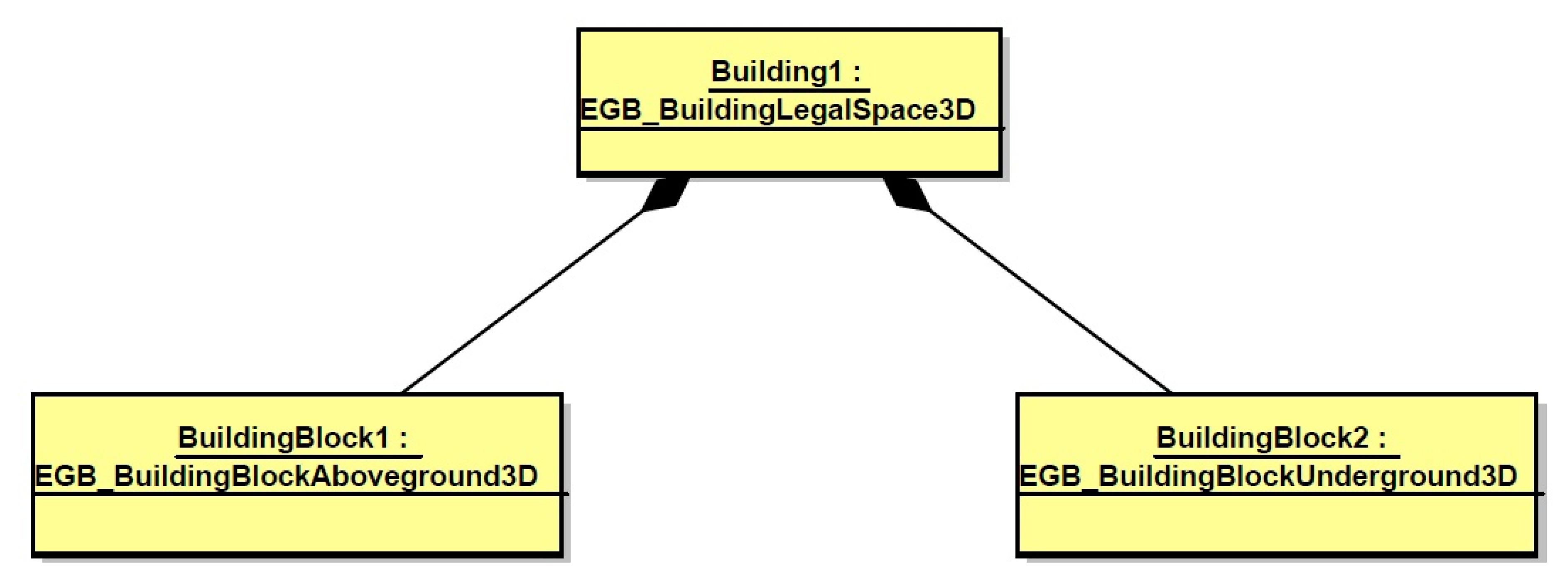
Figure 13.
Possible cases of access to (an) underground object(s): (a) underground part is the object within one property, (b) underground part is divided between two properties, (c) underground part is divided between two properties having access to it, (d) underground part is divided between properties having access to it (in this case three properties). Source: own study.

Figure 14.
The UML schema of instance where the underground part is a separate object within one property.
Figure 14.
The UML schema of instance where the underground part is a separate object within one property.
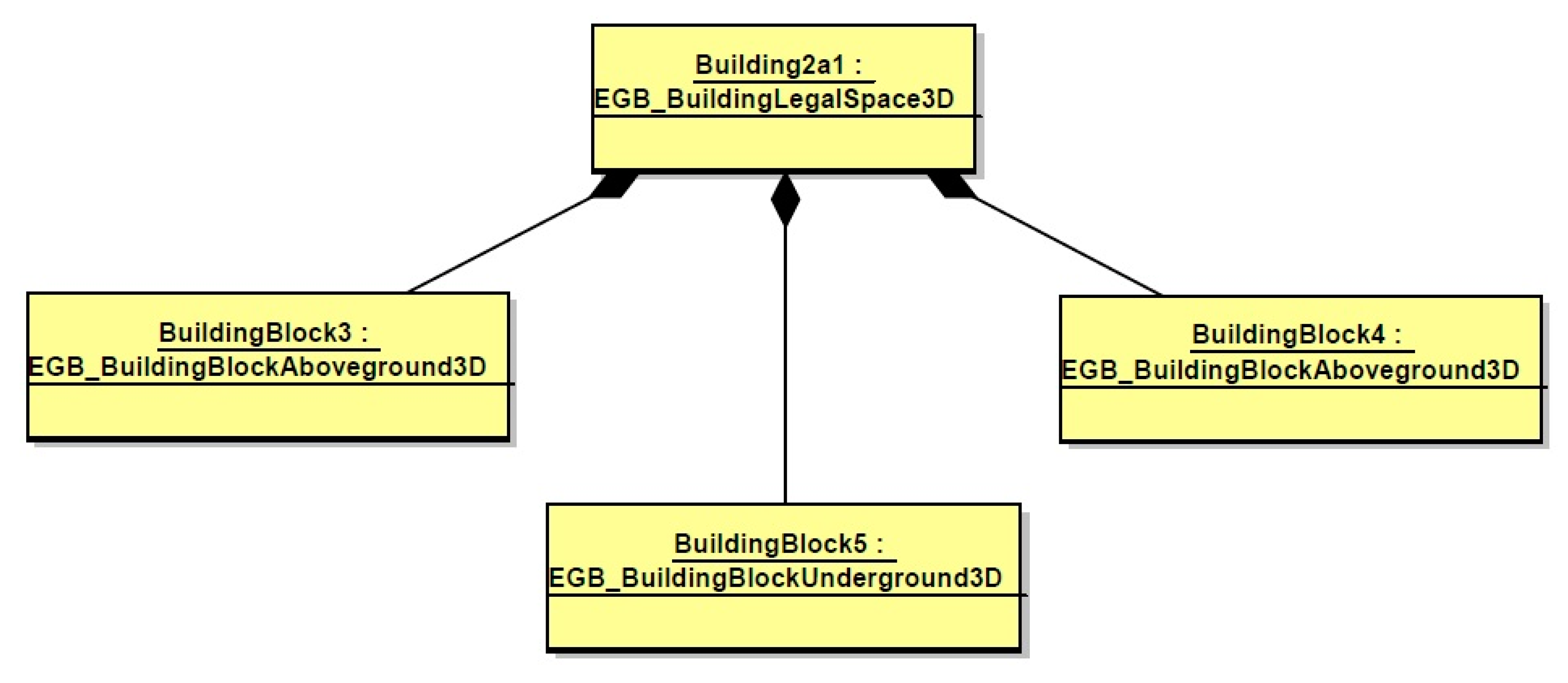
Figure 15.
The UML schema of instance where the underground part is divided, all within one property.
Figure 15.
The UML schema of instance where the underground part is divided, all within one property.

Figure 16.
The UML schema of instance where underground part is divided between two properties.

Figure 17.
The UML schema of instance where the underground part is divided between two properties having access to it.
Figure 17.
The UML schema of instance where the underground part is divided between two properties having access to it.
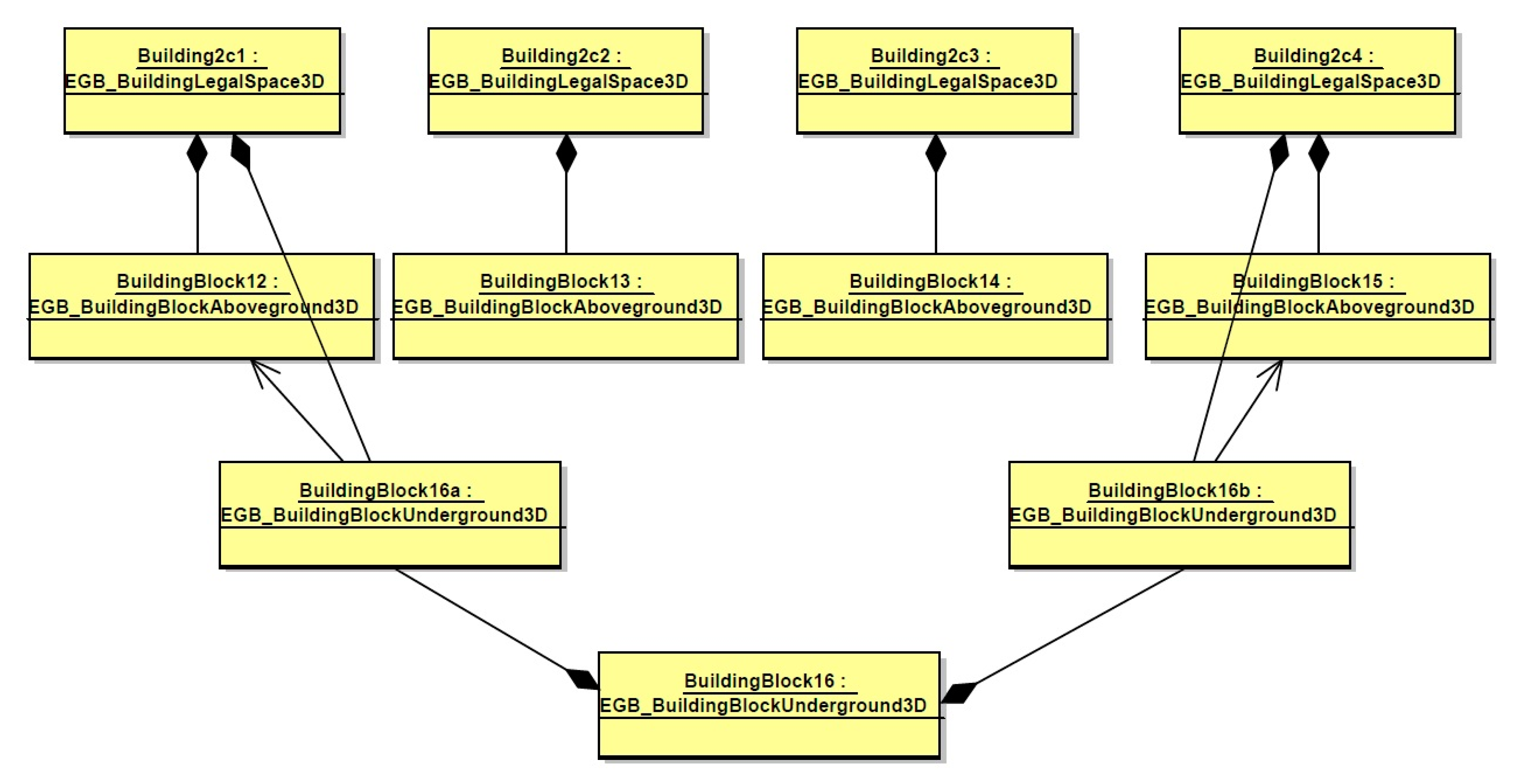
Figure 18.
The UML schema of instance where the underground part is divided between properties having access to it (in this case three properties).
Figure 18.
The UML schema of instance where the underground part is divided between properties having access to it (in this case three properties).

Figure 19.
The point cloud of the Underground Tourist Route and the Main Market Square coloured by RGB values with the surface model.
Figure 19.
The point cloud of the Underground Tourist Route and the Main Market Square coloured by RGB values with the surface model.

Figure 20.
Three-dimensional model of the Underground Tourist Route.

Figure 21.
Three-dimensional model of the Underground Tourist Route with buildings.

Figure 22.
Relationships between classes representing the Underground Tourist Route objects, buildings (and related objects), and cadastral parcels.
Figure 22.
Relationships between classes representing the Underground Tourist Route objects, buildings (and related objects), and cadastral parcels.

Figure 23.
UML schema of objects making the Underground Tourist Route.

Figure 24.
Blocks forming the Underground Tourist Route in Rzeszów: (a) 3D side view; (b) underground objects in 2D view.
Figure 24.
Blocks forming the Underground Tourist Route in Rzeszów: (a) 3D side view; (b) underground objects in 2D view.
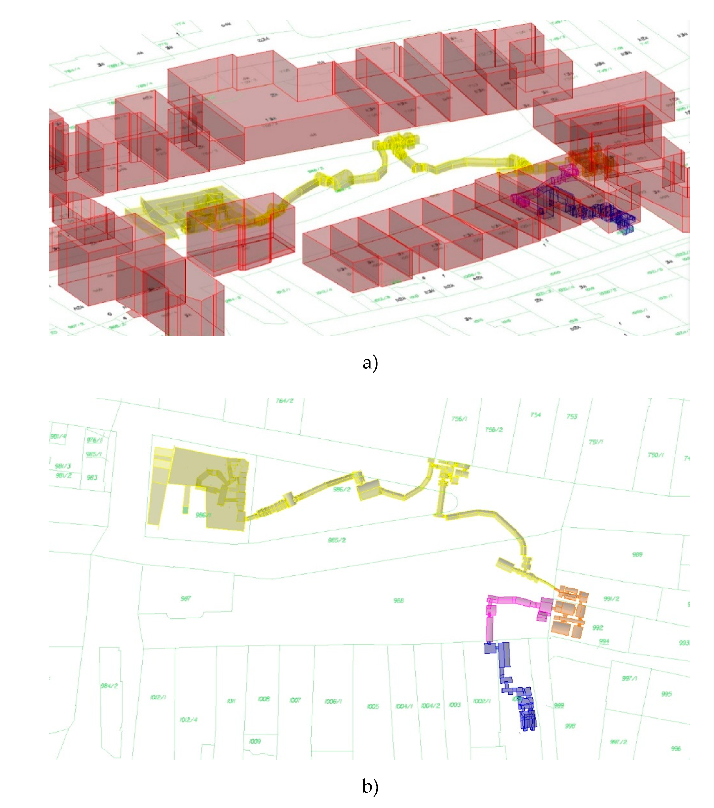

Table 1.
Characteristics of Rzeszów in comparison with the region and the country.
| Territory | Poland | Podkarpackie Province | Rzeszów |
|---|---|---|---|
| Area (km2) | 312,705.25 | 17,845.76 | 126.61 |
| Population | 38,411,148 | 2,129,015 | 191,564 |
| Population density (pers./km2) | 123 | 119 | 1591 |
| Number of parcels | 37,240,562 | 3,133,457 | 89,826 |
| Average parcel area (m2) | 8396.8 | 5695.2 | 1409.5 |
| Number of buildings | 18,359,501 | 1,026,738 | 42,620 |
| Building density (bld/km2) | 58.7 | 57.5 | 336.6 |
| Status on | 1 January 2019 | 1 January 2019 | 12 February 2020 |
Source: own study.
Table 2.
Proposal of additional attributes for underground objects.
| Attribute | Possible Value |
|---|---|
| contour type | External Internal |
| contour measurement source | measurement of external contour measurement of interior and determining the external contour on the basis of documents measurement of interior and wall thickness detection with additional equipment measurement of interior |
| positioning error in relation to the control network | 0–0.10 m 0.11–0.30 m 0.31–0.60 m 0.61–1.50 m 1.51–3.00 m 3.00 m or more |
Source: own study.
Table 3.
Characteristics of the land parcels under which the Underground Tourist Route is located.
| Parcel No. | Owner | Additional Tenure | Building | Description |
|---|---|---|---|---|
| 985/2 | city of Rzeszów municipality | no | no | Main Market Square |
| 986/1 | city of Rzeszów municipality | management | yes | cultural institution building (entrance to underground passageways) |
| 986/2 | city of Rzeszów municipality | no | no | Main Market Square |
| 988 | city of Rzeszów municipality | no | no | Main Market Square |
| 991/2 | private owner | no | yes | residential building |
| 992 | private owner | no | yes | hotel (possible exit from underground passageways) |
| 1001 | city of Rzeszów municipality | no | yes | office building (exit from underground passageways) |
| 1002/1 | city of Rzeszów municipality | no | yes | office building |
Source: own study.
© 2020 by the authors. Licensee MDPI, Basel, Switzerland. This article is an open access article distributed under the terms and conditions of the Creative Commons Attribution (CC BY) license (http://creativecommons.org/licenses/by/4.0/).
Share and Cite
MDPI and ACS Style
Bieda, A.; Bydłosz, J.; Warchoł, A.; Balawejder, M. Historical Underground Structures as 3D Cadastral Objects. Remote Sens. 2020, 12, 1547. https://doi.org/10.3390/rs12101547
AMA Style
Bieda A, Bydłosz J, Warchoł A, Balawejder M. Historical Underground Structures as 3D Cadastral Objects. Remote Sensing. 2020; 12(10):1547. https://doi.org/10.3390/rs12101547
Chicago/Turabian StyleBieda, Agnieszka, Jarosław Bydłosz, Artur Warchoł, and Monika Balawejder. 2020. "Historical Underground Structures as 3D Cadastral Objects" Remote Sensing 12, no. 10: 1547. https://doi.org/10.3390/rs12101547
Note that from the first issue of 2016, this journal uses article numbers instead of page numbers. See further details here.