3D Point Cloud and BIM-Based Reconstruction for Evaluation of Project by As-Planned and As-Built


1
Department of Architecture, Yeungnam University College, 170 Hyeonchung-ro, Nam-gu, Daegu 42415, Korea
2
School of Architecture, Yeungnam University, 280 Daehak-ro, Gyeongsan-si, Gyeongbuk 38541, Korea
3
School of Architecture & Civil Engineering, Kyungpook National University, 80 Daehak-ro, Buk-gu, Daegu 41566, Korea
*
Author to whom correspondence should be addressed.
Remote Sens. 2020, 12(9), 1457; https://doi.org/10.3390/rs12091457
Submission received: 16 March 2020
/
Revised: 27 April 2020
/
Accepted: 1 May 2020
/
Published: 4 May 2020
Abstract
:Progress management of a construction project can detect changes early by visualizing the progress of the project, as it is important to be capable of predicting the success or failure of future project objectives. However, to perform reliable progress management tasks, accurate measurement data is required. In this study, the basic principle of the evaluation of project progress was performed through the 3D point cloud and the 4D attributes of BIM. The evaluation of project progress proposed in this study was based on as-built data to assess the progress of the project site. The specific improvements via the proposed process for this study in the construction project-progress control area were as follows: (1) visualization of construction project progress, (2) calculation of project as-built quantity, and (3) evaluation of a project’s progress. This study improved the efficiency and productivity in the management of a construction project through detection of the progress process. It provided easy monitoring of the overall project status, such as productivity analysis, progress rate and quality verifications, and easy identification of the problems created and foreseeable engineering tasks.
1. Introduction
Effective progress control is essential for successful project progression, which is determined by the level of awareness of the participant of the current progress status [1,2]. Efficient construction project management requires timely and accurate progress measurement; therefore, detailed progress information should be collected and managed to improve the accuracy of progress measurement. However, timely data collection of the progress of a construction project requires a significant amount of effort, and the burden of the indirect costs that accompany this task hinders accurate progress measurement [3]. Therefore, a method to improve the accuracy and timely measurement of progress can be the most crucial aspect of progress management.
In recent construction projects, immediate decision-making, precise situational judgment, and proper managerial action have become increasingly important owing to the complexity of large-scale and high-rise buildings. Therefore, concrete and practical research on project progress management is necessary to realize competitiveness in terms of productivity and efficiency of construction projects. The purpose of this study was to propose a method to improve the efficiency and accuracy of progress data collection, which is essential in the progress management of a construction project. For this, a new management plan for project progress management is proposed that includes elements such as automation of progress data collection, a visualization method, and project progress evaluation.
2. Literature Review
2.1. Problems in Calculation of Progress Rate
Typical progress measurement methods that have been used include an estimated progress measurement method, which estimates according to the subjective judgment of a manager, and a method of measuring the actual workload, which calculates the progress rate based on the actual amount of workload spent [4,5,6]. Although these methods are effective in measuring the progress rate of small projects for a single facility, they are not so in large-scale projects [7]. Measuring the progress of a large-scale project requires the quantitative management of the progress rate, which changes as the project progresses [8,9]. In a construction project, quantifying construction activity and workload is to calculate the amount of completed work and the amount of work that needs to be completed in the future. This is significant because project status can be identified efficiently in short and future schedules or changes can be predicted and modified through the quantification [10]. However, despite efforts in reliable progress measurement activities, many problems still exist in collecting and utilizing this data in a timely manner, and these activities require much effort and cost [11].
More than 53% of construction projects have their scheduled plans delayed, and more than 66% do not meet their budget requirements [12]. To manage the progress of a construction project, it is necessary to collect basic data that integrate the schedule and cost, and to understand the work progress rate at each period by comparing progress with the scheduled plans. However, various problems, such as the degradation of objectivity and credibility, lead to inconsistency between the planned and actual progress rates [13].
A typical problem is the use of the impractical method for calculating the progress rate. Hendrickson et al. [14] defined the following four items for the basic approach of measuring the progress rate: 1) measurement of completed individual work, 2) measurement of completed planned milestones, 3) subjective judgment of the project manager, and 4) ratio of the labor cost to the construction cost. However, because most of the currently used progress management for construction projects is based on statement-based work or the critical path method (CPM) without standard criteria, different calculation standards and methods are used each time [13]. In addition, the limited collection of progress rate data is a major obstacle [15,16]. The most economical way to obtain this type of information is through automation [17,18,19]. However, in most project sites, data are still collected through passive methods, such as paper documents [4]. In other words, many time and space constraints remain, as the manager and client must visit the site and collect photographs and documents to track the progress of the project.
2.2. Acquisition and Tracking of Automation-Based Progress Data
In recent years, several types of methods used to integrate various progress data collection technologies have been researched [20,21,22,23]. One method involves the integration of photogrammetry and light detection and ranging (LIDAR) methods and has been found to be effective in collecting high-quality progress data. Another method integrates mobile IT technology, such as RFID and UWB, to collect more accurate progress data. However, these methods have not been used widely in the construction project space, and they remain in the conceptual stage from the automation perspective.
Studies have been conducted to verify the progress by comparing as-built 3D models collected through LIDAR with those produced during the design phase [24]. Representative studies in this area have examined monitoring methods for the process and interference of mechanical, electrical, and plumbing (MEP) by comparing two 3D models or by utilizing other methods to create 3D models via actual progress data acquired by LIDAR [25]. Studies on the visualization of process rate monitoring through a 4D simulation model were conducted in combination with modeling based on laser scanning. Han and Golparvar-Fard [26] developed a progressive model via laser scanning and studied the construction progress through building information modeling (BIM). Patraucean et al. [27] also conducted research on the modeling method for the progressive status of a project through BIM. Meanwhile, Adan et al. [28] focused on the recognition of objects. After segmenting the point clouds corresponding to the walls of a building, a set of candidate objects was detected independently in the color and geometric spaces, and an original consensus procedure integrated both results to infer recognition. In addition, the recognized object was positioned and inserted in the as-is semantically rich 3D model, or BIM model. Wang et al. [29] developed a technique to automatically estimate the dimensions of precast concrete bridge deck panels and create as-built building information modeling (BIM) models to store the real dimensions of the panels. The experimental results revealed that the proposed technique can accurately and efficiently estimate the dimensions of full-scale precast concrete bridge deck panels with an accuracy of 3 mm, and automatically create as-built BIM models of the panels. This study is particularly appropriate for the construction context, since most building components are comprised of planar surfaces. Hence, corresponding planes from two scans can be identified for the registration of the two scans. Bueno et al. [30] presented a novel automatic coarse registration method that is an adaptation of as-is 3D point clouds with 3D BIM models. The experimental results revealed that the method delivers a non-negligible reduction in computational time (approx. 20%) but at no additional benefit in terms of its effectiveness in finding the correct transformation. Rebolj et al. [31] proposed a methodology including three parameters (minimum local density, minimum local accuracy, and level of scatter) to measure the quality of point cloud data for construction progress tracking. The results indicate that the defined quality criteria can be effectively applied when deciding on the appropriate scanning methodology for successful scan-vs-BIM identification. Although a recent study investigated the relationship between the quality of point cloud data and the successful identification of building elements, research is still lacking that identifies the required point cloud data quality for each specific application.
Recently, the use of BIM in construction projects has been increasing, and studies have been conducted to obtain the data and measurement values that are necessary to calculate quantity through 3D models. A representative study was performed by Hartmann et al. [32] in which the possibility of using BIM to calculate quantity in automated construction projects was demonstrated. Monteiro and Martins [33] presented a detailed modeling approach that allows users to extract quantities based on current specifications. Wijayakumar and Jayasena [34] proposed further improvement of the interoperability and quantity extraction part of BIM for an automated quantity calculation method suitable for integration. BIM can calculate quantity based on the attributes of the 3D model, but additional research on the calculation of the project cost is necessary. Eastman et al. [35] pointed out that BIM-based tools for quantitative computation have been developed; however, BIM software with project cost-estimating capabilities is not available. Therefore, it is reportedly troublesome to export BIM-based quantitative calculation data to cost estimation software when calculating project cost. Because of this problem, Lawrence et al. [36] constructed a mapping that enables the interworking between the BIM object and the cost data to update cost estimates because of design changes from the initial design stage of a construction project. However, the objective of this method is to estimate the total cost of design changes only, and does not consider detailed cost items.
3. Proposed System Process
3.1. Progress Status Visualization Plan
The basic concept of progress management is to manage the progress of the process of actual project execution based on the progress schedule created by the project plan. In this study, the building information modeling (BIM) model was used to visualize the planning progress. The BIM template was created based on the progress chart, and the scope of the planning progress was visualized. Actual progress was measured and compared with the planning progress to understand such metrics as the reduced construction period, construction delays, and timing for the construction cost. However, a review of existing research indicated that the timely collection of as-built data is limited by the inherent characteristics of actual construction sites. In this study, a reverse engineering concept was applied for the timely collection of as-built data. The collection of 3D point cloud data, which is the basis for reverse engineering, was collected via drone and LIDAR.
The progress status was confirmed by comparing the BIM 3D view model with the 3D point cloud matching model. The BIM 3D view model was modeled through the BIM template setting based on the planning process table, and the 3D point cloud matching model was modeled based on the data collected from the drone and LIDAR. Volume comparisons between the two models were conducted because the as-built data collection was based on a three-dimensional shape. By comparing the two types of 3D models, it is possible to visualize the actual progress status of the construction project, which is not possible with the conventional method, which only utilizes documentation.
3.2. 3D Mesh Modeling
Delanay triangulation (DT) and the Voronoi diagram (VD) are essential elements for mesh modeling. DT is a division in which points on a plane are connected in triangles to divide the space such that the minimum value of the cabinet is maximal, and the outer source of any triangle does not include anything other than the three vertices of the triangle [37]. Meanwhile, a VD is a division of a plane into polygons that contain each of these points when there are points on the plane [38]. Figure 1a is an expression of DT, and when there are dots on the plane, there exist various ways to connect these points to form triangles, as displayed in (2) and (3). Of these various triangulations, the division in which each triangle is as close as possible to the regular triangle is presented in (2). Figure 1b is an expression of a VD, and when there are points on the plane, the two adjacent generation points should be connected to the line, and a vertical equal division of this line should be drawn. In this way, a vertical isomeric line is drawn, creating a polygon with a vertical isomeric line that divides the sides into polygons. DT and VD are in a dual relationship, and if one is known, the other can immediately be obtained. Figure 1c displays VD (1) and the DT (2) of the same set of points. The VD is created by sequentially linking the center of the circumcircle of DTs with generating points as a common vertex, and by linking points between adjacent VD areas, DT can be generated for these points [39]. For 3D stereoscopic modeling from 3D point clouds, the use of DT allows for polygon mesh to be obtained from a collection of points on the surface. The triangulation in 3D is called tetrahedralization or tetrahedrization [40]. A tetrahedralization is the partitioning of the input domain into a collection of tetrahedra that meet at only shared faces (vertices, edges, or triangles). Polygons are typically ideal for accurately representing the results of measurements, providing an optimal surface description. However, the results of tetrahedralization are much more complicated than those of a 2D triangulation. Therefore, this study was performed by utilizing the Commercial Modeling Software Package. The Leica Cyclone platform was used for 3D point cloud data visualization and processing, and the Leica 3D Reshaper platform was used for polygon mesh model generation.
3.3. Comparison of the BIM Model and the Mesh Model
The BIM modeling tool used in this study was Autodesk Revit software, which used the platform to compare the progress of as-planned and as-built data. Clear planning criteria are needed to compare the performance against the plan through the collection of as-built data. In this study, the period-specific BIM model generated based on the start and end dates of construction elements was used as the as-planned data of the project, and the 3D model generated based on the 3D point cloud was used as the as-built data. For this comparison, the 3D mesh model created based on the 3D point cloud should be imported into the BIM model. However, the two types of 3D models have different operating software bases and therefore must be imported through file conversion. The process for performing this task is presented in Figure 2.
- (1)
- Select the as-built 3D mesh model based on a 3D point cloud that requires export, and convert it to DXF format.
- (2)
- Activate the BIM model (gray color) that becomes the as-planned model, and import the as-built 3D mesh model (yellow color) that has been converted to the DXF file.
- (3)
- Overlap the two 3D models to compare the differences. The area where the difference has been confirmed means that the work part needs to be carried out in a planned manner or that the work has not actually been done, and the difference in progress can be easily confirmed through color comparison.
3.4. Identification of Recognition Rate and Determining Error of Aligned Data
This study acquired point cloud data and verified the accuracy of data obtained using LIDAR, which can scan both the exterior and interior of buildings using a drone that can capture an area inaccessible to managers. This study also examined a method of acquiring available data using post-processing, and finally determined the accuracy and error of the data acquisition according to building shapes. In this study, two buildings were selected to acquire point cloud data, which were obtained from the framework of those buildings, that is, from columns, girders, beams, and slabs. Table 1 presents details of Buildings A and B, where point cloud data were collected for accuracy verification. The scanning interval was set with an overlap of at least 50%–60%. Thus, the recognition rate of the members was 100%, and the cloud data could be reliably acquired using LIDAR.
Building A was selected to verify the accuracy of object recognition. However, this building had a rooftop that could not be scanned using terrestrial LIDAR. Therefore, a drone was needed to obtain aerial photos, from which data of the overall external building shape could be aligned. For Building A, 209 photos were obtained by operating the drone. Then, point cloud alignment was carried out using those photos.
The error of the point cloud data was determined by comparing the measurement data of Buildings A and B and the LIDAR-based alignment models of the scanned data. For the measurement data, the real distances between each building were measured using a measuring device. For alignment model data, the distance between point clouds was measured by implementing a software program. Table 2 presents the errors obtained by comparing measurements and LIDAR scanning results for Buildings A and B. It shows that in the case of Building A, the average error values were 0.011 m, 0.012 m, and 0.019 m in the external width, the distance between columns, and the column height, respectively. Meanwhile, in the case of Building B, the average error values were 0.012 m, 0.011 m, and 0.012 m in the external width, the distance between columns, and the column height, respectively. According to the BIM guide for 3D imaging, which is published by the General Service Administration (GSA) of the USA, the error range needs to be a maximum of 51 mm for urban design projects and a maximum of 13 mm for architectural designs. Otherwise, the practical accuracy cannot be maintained. In this study, the errors for each item, which were identified by performing comparative measurements, were between 11 mm and 19 mm, respectively. This result is remarkably close to 13 mm, which is recommended by the GSA for the application of point cloud data to architectural designs. The distance between the two end points of a target member in the scanned data was measured by mouse picking. As this method implies an unavoidable error, the above errors indicate that very accurate data were acquired by this study.
Errors that were present in the point cloud data obtained using a drone were compared in the same way as the LIDAR-based error verification. It showed that the average errors for the width, length, and height of the building were 0.378 m, 0.358 m (distance between columns), and 0.072 m (column height), respectively. These values were far below 13 mm, which is recommended by the GSA for the application of point cloud data to architectural designs. Accordingly, this study used the drone-based point cloud data only for the parts for which data could not be acquired using LIDAR.
3.5. Evaluation of Progress Status
The Earned Value Management System (EVMS) measures the actual progress of the project and allows project risk assessment by considering time and cost [41]. The proposed process in this study evaluated the integrity of the project based on the EVMS. Integrity evaluation of the project was based on planned EV, project EV, and actual EV items, and a variance and performance index were used for the analysis (Figure 3). Variance analysis is related to schedule and cost, and the performance index can be categorized into the Schedule Performance Index (SPI) and Cost Performance Index (CPI).
Schedule variance (SV) indicates the difference in the schedules and the monetary value to reflect the degree of achievement as compared with the schedule obtained through the given measurement method, Equation (1). The equation used to express the SV subtracts the planned workload from the actual workload, and if the value is 0, then the project is progressing on schedule. If the value is negative, the project is behind schedule, while a positive value indicates that the project is ahead of schedule.
SV = EV − PV (= BCWP − BCWS)
Cost variance (CV) is the difference in the construction cost and is obtained by subtracting the actual input cost from the performance workload, Equation (2). If the value is 0, the project is progressing as planned without any delays. If the value is negative, the budget has been exceeded. Finally, a positive value indicates that the budget is within the range.
CV = EV − AC (= BCWP − ACWP)
The Schedule Performance Index (SPI) is a measure of the project schedule efficiency and is calculated as the ratio of the EV value to the PV value, Equation (3). It is calculated through the ratio of the performance workload to the planned workload. If the value is greater than or equal to 1, the construction is being completed faster than the plan, and if the value is less than 1, the construction is not being completed faster than the plan.
SPI = EV/PV (= BCWP/BCWS)
The Cost Performance Index (CPI) is a measure of the project cost-effectiveness and is calculated as the ratio of the EV value to the AC value, Equation (4). If the value is greater than 1, this indicates that the project cost is effective. If the value is less than 1, the project cost is not efficient. Consequently, the fact that it is larger than 1 indicates that the actual cost that is required for the execution of the construction is less than the estimated cost. Therefore, from the perspective of profit and loss, a positive profit margin is indicated.
CPI = EV/AC (= BCWP/ACWP)
4. Project Evaluation Progress Application Plan
4.1. Case Study Site Review
A general construction site, planned to have a land area of 38,398 m2 and a floor area of 52,260 m2, was used for the case study. The construction period was 690 d, and the main building of the completed project was a 9-story building with one basement. This construction, unlike a typical construction in which a building is constructed, involved plans for the existence of various spaces, such as an integrated lobby, civil affairs office, multipurpose conference center, cultural activity room, childcare facility, and office space. Therefore, simultaneous construction was impossible. Furthermore, the project required that simultaneous construction be conducted starting from the ground excavation, owing to the wide site area, ground condition, and adjacent roads.
The target site was divided into 10 districts and the start time and finish time of each zone were accordingly different. Therefore, careful monitoring of the construction progress was required. In addition, because of the nature of the simultaneous construction, several problems were expected to arise in the timely collection and utilization of data. Therefore, the construction site was remarkably suitable for the present study based on the applicability of the proposed progress management process, and the application of the data collection was also quite relevant.
In this study, the scope of the application of as-built data was limited to the frame construction in the construction project. This is because the main tasks of framing frame construction are steelwork and formwork, which require a large workforce, and these tasks are typically the main types of jobs that delay an entire construction project period. The collection period of as-built data lasted until the 10 divisions of the construction site were matched, and the use of collected as-built data lasted until the concrete deposition was completed. Typical types of framing construction work can be classified into reinforcing bars, formwork, and depositing concrete, and it is determined that frame structures are created if the concrete deposition is completed. However, the formwork and reinforcing bar tasks can be collected in the as-built data, which was acquired during the 3D point cloud data collection. Therefore, in the present study, the data were classified as noise to perform the editing operation. The procedure for the case study is illustrated in Figure 4.
4.2. Determination of As-Built Data Collection Date through Progress Schedule Analysis
For the baseline plan of this study, the collection date of the as-built data was confirmed based on the concrete deposition date, according to the progress schedule, and the collection period was limited to five months, which was the time period from the start date of the actual concrete deposition after the commencement of construction to the time when the divided districts were matched. Figure 5 presents the dates when the as-built data were confirmed and collected based on the progress schedule and the collection plan of the as-built data, in which the data were collected five times at 30-d intervals from the start date of the first deposition.
4.3. Determination of As-Planned Visualization through Generation of the 3D View BIM Template
For the as-planned visualization, a 3D view BIM template was created for each as-built data collection plan date in Figure 5. Figure 6 shows the as-planned template generated at each point when corresponding projects should have been completed according to the project plan, and the quantity of construction that should have been achieved using the BIM template calculation function.
5. Implementation of the Project Evaluation Progress
5.1. Generation of an As-Built Data-Based 3D Mesh Model
Based on the as-built data acquisition schedule, the as-built data of the case study site were collected and the 3D point cloud matching model was created based on the collected data. When the site for the case study was scanned, the scan density was adjusted to “low” because the possibility of matching errors was high owing to the size of the site. In addition, the outside was scanned by a drone, and the internal data were acquired by LIDAR. Data matching was performed using visual alignment, and the 3D model was generated through the automatic-based model generation method. The noise editing of the final matching model was removed by including the reinforcing bars and concrete-form members, but not the concrete members, as mentioned above. Finally, a 3D mesh model based on the 3D point cloud with five matched divisions was created. Figure 7 shows 3D models at the time when the completed as-built data were acquired.
5.2. Visualization of Project Status and Comparison of Work Progress
To visualize the progress state in the present study, 3D models based on as-planned and as-built data must be moved to a single space. Therefore, the final 3D mesh model, generated through the 3D point cloud matching, was transformed such that it could be operated with a BIM-based 3D model in a single space. Figure 8 presents the implemented visualization of the current status of the as-built data collection, compared with the progress schedule. The procedure was conducted through the overlap of the 3D models, and the area where the progress difference occurred could be checked visually.
The volume comparison of the proposed process can be performed by extracting the volume information of the BIM, as the BIM model, constructed in the design stage, which receives the quantity information of each member simultaneously. The information of all objects that are to be calculated can be displayed in a table format. Figure 8 shows the process of calculating the quantity of as-built concrete from the BIM. This is the quantity that excludes the area where the progress difference occurred, and was calculated after the corresponding part in the BIM 3D model was excluded.
Results of the process proposed in this study may be different depending on the modeling ability of the user, the missing data in 3D point cloud data matching, and overlap level with the as-built data. The accuracy of the completed as-built 3D model was verified. The verification method was conducted based on the comparison between the 3D model of the as-built data, which was calculated for each schedule, and the quantity based on the concrete invoices that were collected at the site.
Table 3 lists the details of the concrete quantity at the time of as-planned and as-built data collection for each schedule, displaying the volume comparison of the difference between the actual input quantity and planned input quantity. Because of the comparison, the difference between the quantity of the 3D model based on as-built data, which was collected five times, and the quantity that was calculated based on the ready-mixed concrete invoice was found to be about 49 m3, or about 9 m3 at each time. Considering that the average amount of concrete accumulated at each time was about 2,500 m3, it was confirmed that the error rate was less than 0.5%, which indicates that the accuracy is high. Particularly, in the actual site, it was confirmed that the accuracy can be increased by considering the errors that were caused by the installation of the formwork and the thickness difference between the members that were actually completed and the planned thickness of the members.
5.3. Project Progress Evaluation
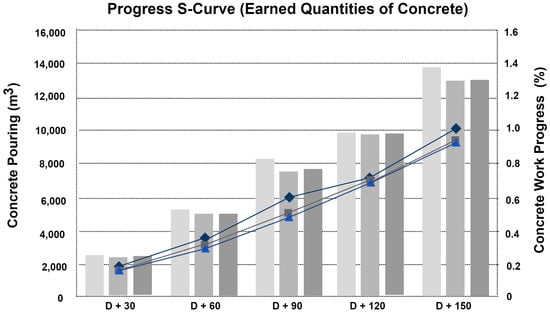
Figure 9 is based on the progress data of the case study site, and the evaluation was conducted based on planned EV, project EV, and actual EV. The planned EV indicates the quantity of as-planned concrete deposition, the project EV indicates the quantity of as-built data-based deposition, and the actual EV indicates the quantity based on the ready-mixed concrete deposition. The case study was conducted based on the analysis of the variance and performance index, and the results are as follows.
- At each time of the as-built data collection, it was found that the project was delayed more than planned. This can be found through the m3 and % value of the planned EV and the project EV.
- Variance analysis was reviewed based on the project SV, revealing that the project progress was delayed more than planned at each time of the as-built data collection. This can be found through the comparison of the project EV and planned EV.
- The Schedule Performance Index values at each time point were found to be less than 1. This indicates that the performance was worse than the planned value, and especially at D + 90, the progress integrity was confirmed to have been degraded significantly.
6. Conclusions
This study was conducted to propose a method to improve the efficiency and accuracy of the as-built data collection method, which is essential to understanding the progress status. Through the related research trends, the cause analysis and related technology trends on the limit of progress management in current construction projects were studied, and the project evaluation process presented in this study was verified through a case study. The existing process of collecting project progress data is inefficient and highly vulnerable to quick decision-making and immediate action by project managers. The as-built data collection method presented in this study would be possible as an efficient means for project managers to determine project progress and to perform comprehensive project management tasks. In particular, rapid decision-making based on the rapid delivery of information could prevent work errors and the need for reconstruction work; therefore, it could limit waste during the construction period and save on cost. In addition, the results of this study demonstrate that it is possible to improve the management of the efficiency and productivity of construction projects. Therefore, various advantages are possible, such as monitoring the overall situation of the project, productivity analysis of the construction project, progress rate verification, and quality verification. Therefore, it would be easy to identify problems and predictable engineering work. The conclusions of this study are as follows.
- The proposed project evaluation process confirmed the difference in the project progress through 3D visualization. This allowed project managers to easily track project progress and identify precise status when progress did not proceed as planned.
- The workload verification of the proposed project evaluation process was conducted through volume comparison, which utilized the BIM volume information extraction function. Because of the verification, the difference between the quantity of actual concrete deposition and the quantity of the 3D model created based on the as-built data was insignificant. In addition, in the actual field, the accuracy was confirmed to be higher when the quantity change of the concrete deposition was considered.
- The project integrity evaluation method was based on the quantity-based EV value, verifying that progress could be evaluated through variance and performance index analyses.
In this study, the quantity of the progress could be calculated through the as-built data collection; however, there was a limit to calculating the cost. Although costs can be calculated by including the unit price for each material in the BIM model and interworking this with the quantity calculation, the indirect costs of the actual project cannot be included. Therefore, further research on project cost calculation is necessary. In addition, this study was conducted to determine construction progress through manual labor. If an automatic quantification method is developed, it would be possible to speedily transmit information in project progress management.
Author Contributions
Conceptualization, S.K. (Seungho Kim), S.K. (Sangyong Kim), and D.-E.L.; data curation, D.-E.L.; formal analysis and investigation, S.K. (Sangyong Kim); methodology, S.K. (Seungho Kim), S.K. (Sangyong Kim), and D.-E.L.; project administration, S.K. (Sangyong Kim); resources, D.-E.L.; software, S.K. (Seungho Kim) and S.K. (Sangyong Kim); supervision, S.K. (Sangyong Kim) and D.-E.L.; validation, S.K. (Seungho Kim), S.K. (Sangyong Kim), and D.-E.L.; visualization, S.K. (Seungho Kim); writing—original draft, S.K. (Seungho Kim) and S.K. (Sangyong Kim); writing—review and editing, S.K. (Sangyong Kim) and D.-E.L. All authors have read and agreed to the published version of the manuscript.
Funding
This work was supported by the National Research Foundation of Korea (NRF) grant funded by the Korean government (MSIT) (No. NRF-2018R1A5A1025137).
Conflicts of Interest
The authors declare no conflict of interest.
References
- Hegazy, T. Construction progress control. In Computer-Based Construction Project Management; Prentice Hall: Upper Saddle River, NJ, USA, 2002; pp. 289–316. [Google Scholar]
- Teizer, J.; Lao, D.; Sofer, M. Rapid automated monitoring of construction site activities using ultra-wideband. In Proceedings of the 24th International Symposium on Automation and Robotics in Construction, Kochi, Kerala, India, 2007; pp. 23–28. [Google Scholar]
- Memarzadeh, M.; Golparvar-Fard, M.; Niebles, J. Automated 2D detection of construction equipment and workers from site video streams using histograms of oriented gradients and colors. Automat. Constr. 2013, 32, 24–37. [Google Scholar] [CrossRef]
- Choi, Y. Construction progress management system by tracking the work-done performance. Korean J. Constr. Eng. Manag. 2003, 4, 137–145. [Google Scholar]
- Eldin, N. Measurement of work progress: Quantitative technique. J. Constr. Eng. Manag. 1989, 115, 462–474. [Google Scholar] [CrossRef]
- Won, D.; Kim, W.; Lee, H. Methods of Establishing the Optimal Performance Measurement Baseline and Evaluating the Progress for Implementing EVMS; Korea Institute of Construction Engineering and Management: Seoul, Korea, 2001; pp. 395–400. [Google Scholar]
- Ko, S.; Chi, S.; Kim, J.; Song, J. Development of Progress Measurement Framework for Mega Construction Project. J. Korean Soc. Civ. Eng. 2017, 37, 419–425. [Google Scholar] [CrossRef] [Green Version]
- Hyun, C.; Kim, J.; Park, I.; Yu, J.; Son, B.; Hong, T.; Kim, C. Development of the Program Management System for Mega Project in Urban Regeneration; Korea Institute of Construction Engineering and Management: Seoul, Korea, 2008; pp. 183–192. [Google Scholar]
- Lee, S.; Seo, Y.; Lee, S. Progress management system model for multiple construction projects. JAIK 2010, 26, 79–86. [Google Scholar]
- Park, J. A Study on the Schedule Process for Forecasting Progress Rate for Construction Project; Gyeonsang National University: Jinju, Korea, 2011. [Google Scholar]
- Bayrak, T. Semi-Automatic Construction Progress Measurement Using a Combination of CAD Modelling, Photogrammetry and Construction Knowledge. Ph.D. Thesis, Heriot-Watt University, Edinburgh, UK, 2008. [Google Scholar]
- Han, K. Model-driven visual data analytics for monitoring work-in-progress on construction sites. Ph.D. Thesis, University of Illinois at Urbana-Champaign, Champaign, IL, USA, 2016. [Google Scholar]
- Chin, S.; Yoon, S.; Choi, C.; Cho, C. RFID+4D CAD for Progress Management of Structural Steel Works in High-Rise Buildings. J. Comput. Civ. Eng. 2008, 22, 74–89. [Google Scholar] [CrossRef]
- Hendrickson, C.; Au, T. Project Management for Construction: Fundamental Concepts for Owners, Engineers, Architects, and Builders; Prentice-Hall: Upper Saddle River, NJ, USA, 1989. [Google Scholar]
- Navon, R.; Sacks, R. Assessing research issues in Automated Project Performance Control (APPC). Automat. Constr. 2006, 16, 471–484. [Google Scholar] [CrossRef]
- Saidi, K.; Lytle, A.; Stone, W. Report of the NIST workshop on data exchange standards at the construction job site. In Proceedings of the 20th International Symposium on Automation and Robotics in Construction, Eindhoven, The Netherlands, 2003; pp. 617–622. [Google Scholar]
- Giretti, A.; Carbonari, A.; Naticchia, B.; DeGrassi, M. Design and first development of an automated real-time safety management system for construction sites. J. Civ. Eng. Manag. 2009, 15, 325–336. [Google Scholar] [CrossRef] [Green Version]
- Cheng, T.; Venugopal, M.; Teizer, J.; Vela, T. Performance evaluation of ultra wideband technology for construction resource location tracking in harsh environments. Automat. Constr. 2011, 20, 1173–1184. [Google Scholar] [CrossRef]
- Woo, S.; Jeong, S.; Mok, E.; Xia, L.; Choi, C.; Pyeon, M.; Heo, J. Application of wifi-based indoor positioning system for labor tracking at construction sites: A case study in Guangzhou mtr. Automat. Constr. 2011, 20, 3–13. [Google Scholar] [CrossRef]
- Guarnieri, A.; Milan, N.; Vettore, A. Monitoring of complex structure for structural control using terrestrial laser scanning (TLS) and photogrammetry. Int. J. Archit. Herit. 2013, 7, 54–67. [Google Scholar] [CrossRef]
- Liu, D.; Cui, B.; Liu, Y.; Zhong, D. Automatic control and real-time monitoring system for earth–rock dam material truck watering. Automat. Constr. 2013, 30, 70–80. [Google Scholar] [CrossRef]
- Maalek, R.; Sadeghpour, F. Accuracy assessment of Ultra-Wide Band technology in tracking static resources in indoor construction scenarios. Automat. Constr. 2013, 30, 170–183. [Google Scholar] [CrossRef]
- Moon, S.; Yang, B. Effective monitoring of the concrete pouring operation in an RFID-based environment. J. Comput. Civ. Eng. 2010, 24, 108–116. [Google Scholar] [CrossRef]
- Bosché, F.; Ahmed, M.; Turkan, Y.; Haas, C.T.; Haas, R. The value of integrating Scan-to-BIM and Scan-vs-BIM techniques for construction monitoring using laser scanning and BIM: The case of cylindrical MEP components. Automat. Constr. 2015, 49, 201–213. [Google Scholar] [CrossRef]
- Turkan, Y.; Bosché, F.; Haas, C.T.; Haas, R. Toward automated earned value tracking using 3D imaging tools. J. Constr. Eng. Manag. 2013, 139, 423–433. [Google Scholar] [CrossRef] [Green Version]
- Han, K.; Golparvar-Fard, M. Appearance-based material classification for monitoring of operation-level construction progress using 4D BIM and site photologs. Automat. Constr. 2015, 53, 44–57. [Google Scholar] [CrossRef]
- Pătrăucean, V.; Armeni, I.; Nahangi, M.; Yeung, J.; Brilakis, I.; Haas, C. State of research in automatic as-built modelling. Adv. Eng. Inform. 2015, 29, 162–171. [Google Scholar] [CrossRef] [Green Version]
- Adan, A.; Quintana, B.; Prieto, S.A.; Bosche, F. Scan-to-BIM for ‘secondary’ building components. Adv. Eng. Inf. 2018, 37, 119–138. [Google Scholar] [CrossRef]
- Wang, Q.; Sohn, H.; Cheng, J.C. Automatic as-built BIM creation of precast concrete bridge deck panels using laser scan data. J. Comput. Civ. Eng. 2018, 32, 04018011. [Google Scholar] [CrossRef]
- Bueno, M.; Bosche, F.; Gonzalez-Jorge, H.; Martinez-Sanchez, J.; Arias, P. 4-Plane congruent sets for automatic registration of as-is 3D point clouds with 3D BIM models. Automat. Constr. 2018, 89, 120–134. [Google Scholar] [CrossRef]
- Rebolj, D.; Pučko, Z.; Babič, N.C.; Bizjak, M.; Mongus, D. Point cloud quality requirements for Scan-vs-BIM based automated construction progress monitoring. Automat. Constr. 2017, 84, 323–334. [Google Scholar] [CrossRef]
- Hartmann, T.; Van Meerveld, H.; Vossebeld, N.; Adriaanse, A. Aligning building information model tools and construction management methods. Automat. Constr. 2012, 22, 605–613. [Google Scholar] [CrossRef]
- Monteiro, A.; Martins, J. A survey on modeling guidelines for quantity takeoff-oriented BIM-based design. Automat. Constr. 2013, 35, 238–253. [Google Scholar] [CrossRef]
- Wijayakumar, M.; Jayasena, H. Automation of BIM quantity take-off to suit QS’s requirements. In Proceedings of the Second World Construction Symposium, Colombo, Sri Lanka, 14–15 June 2013. [Google Scholar]
- Eastman, C.; Teicholz, P.; Sacks, R.; Liston, K. A guide to building information modeling for owners, managers, designers, engineers and contractors. In BIM Handbook; John & Wiley Sons: Hoboken, NJ, USA, 2011. [Google Scholar]
- Lawrence, M.; Pottinger, R.; Staub-French, S.; Nepal, M. Creating flexible mappings between Building Information Models and cost information. Automat. Constr. 2014, 45, 107–118. [Google Scholar] [CrossRef] [Green Version]
- Fortune, S. Voronoi diagrams and Delaunay triangulations. In Computing in Euclidean Geometry; World Scientific: Hackensack, NJ, USA, 1992; pp. 193–233. [Google Scholar]
- Fang, Y.; Friedman, M.; Nair, G.; Rys, M.; Schmid, A.E. Spatial Indexing in Microsoft SQL Server 2008. In Proceedings of the ACM SIGMOD International Conference on Management of Data (SIGMOD 2008), Vancouver, BC, Canada, 10–12 June 2008; pp. 1207–1216. [Google Scholar]
- Ledoux, H. Modelling Three-Dimensional Fields in Geoscience with the Voronoi Diagram and Its Dual. Ph.D. Thesis, University of Glamorgan, Trefforest, UK, 2006. [Google Scholar]
- Remondino, F. From point cloud to surface: The modeling and visualization problem. Int. Arch. Photogramm. Remote Sens. Spat. Inf. Sci. 2003, 34, W10. [Google Scholar]
- Vandevoorde, S.; Vanhoucke, M. A Comparision of Different Project Duration Forecasting Methods Using Earned Value Metrics. Int. J. Proj. Manag. 2006, 24, 289–302. [Google Scholar] [CrossRef]
Figure 1.
Delanay triangulation (DT) and the Voronoi diagram. (a) Delanay triangulation; (b) Voronoi diagram; (c) Same set of points.
Figure 1.
Delanay triangulation (DT) and the Voronoi diagram. (a) Delanay triangulation; (b) Voronoi diagram; (c) Same set of points.
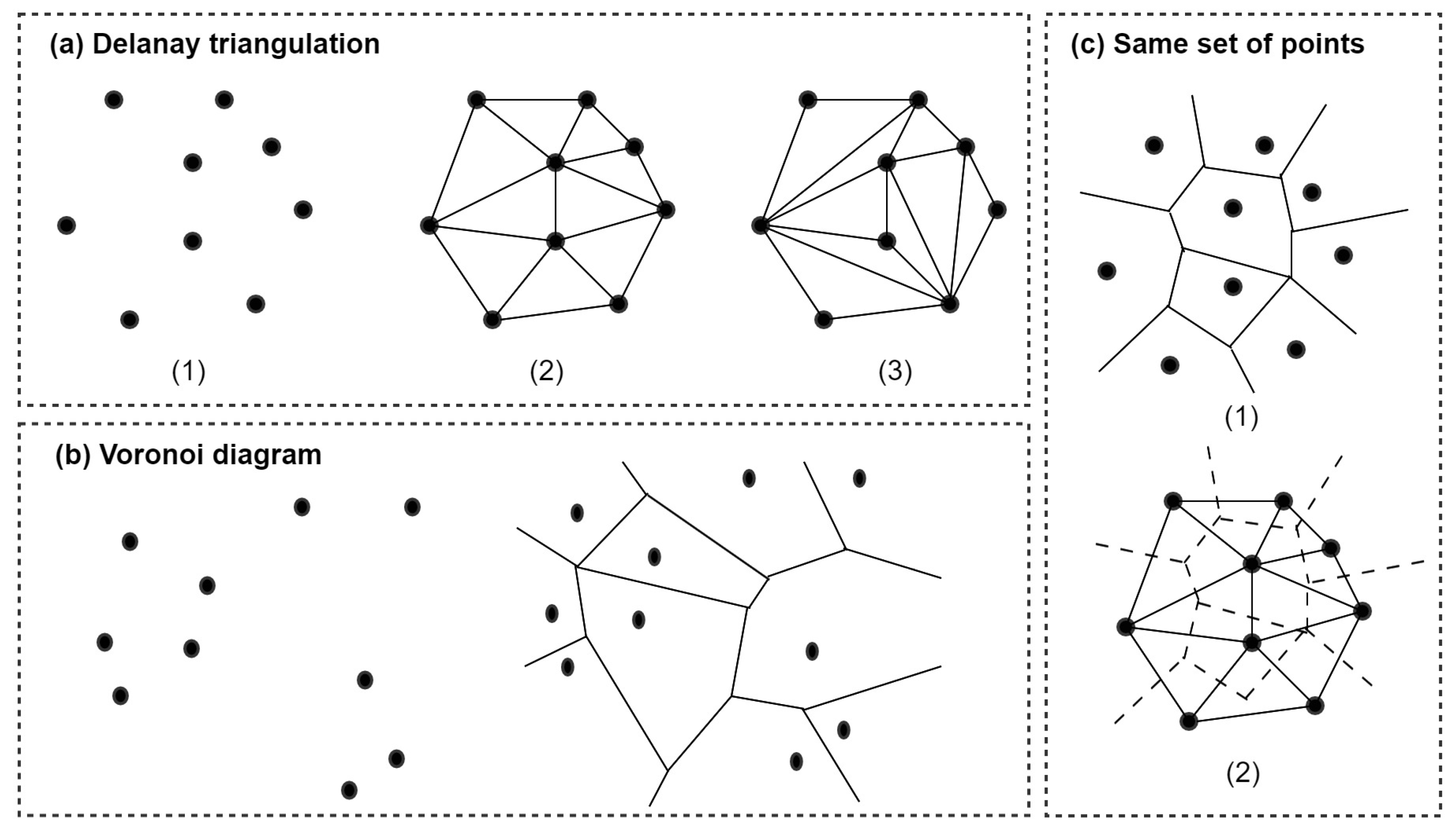
Figure 2.
Comparison of the building information modeling (BIM) model and the point cloud-based model.
Figure 2.
Comparison of the building information modeling (BIM) model and the point cloud-based model.

Figure 3.
Earned Value Management System (EVMS) diagram through the S-Curve.
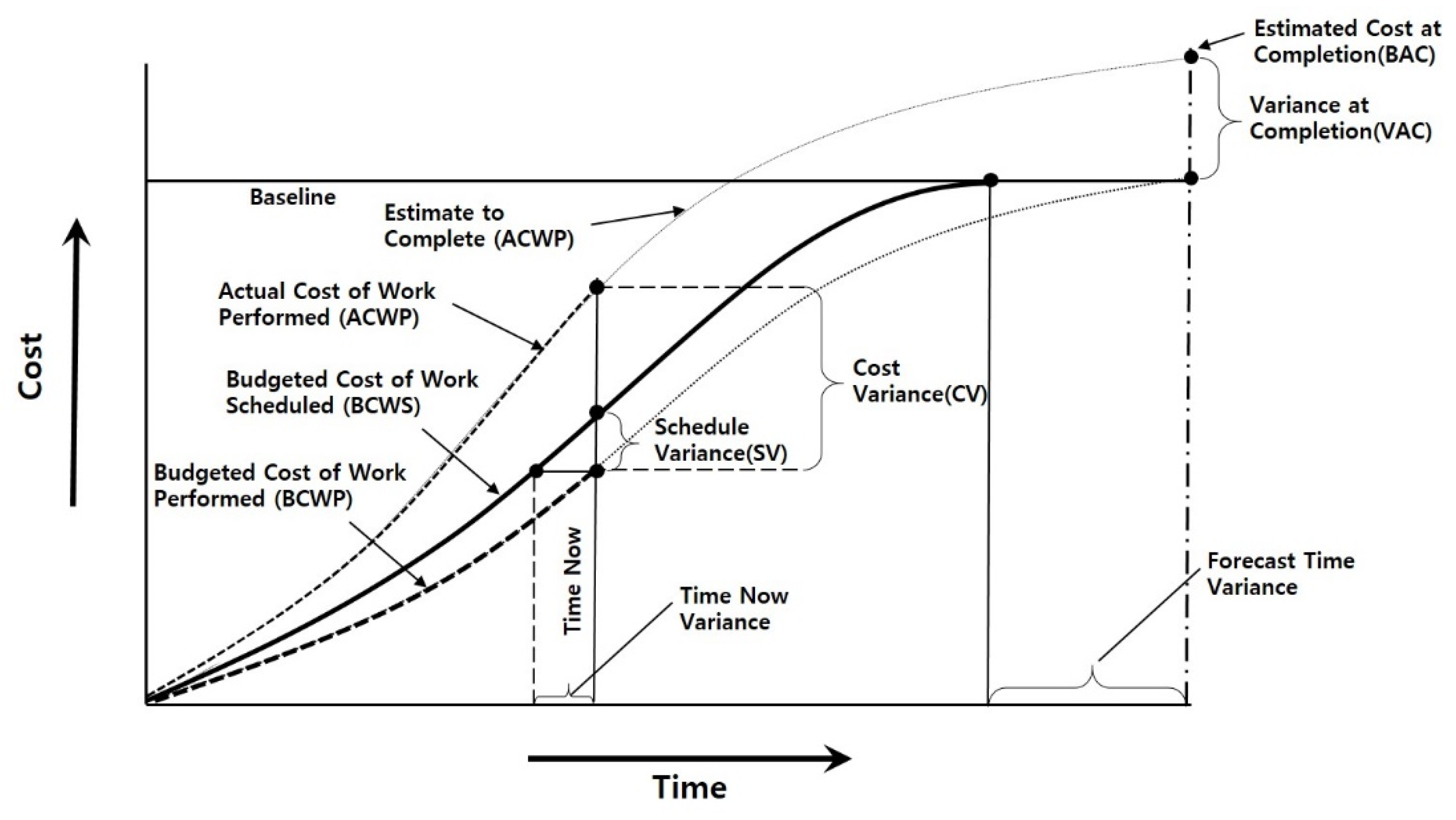
Figure 4.
Procedure for the case study.

Figure 5.
As-built data collection plan based on the progress schedule.
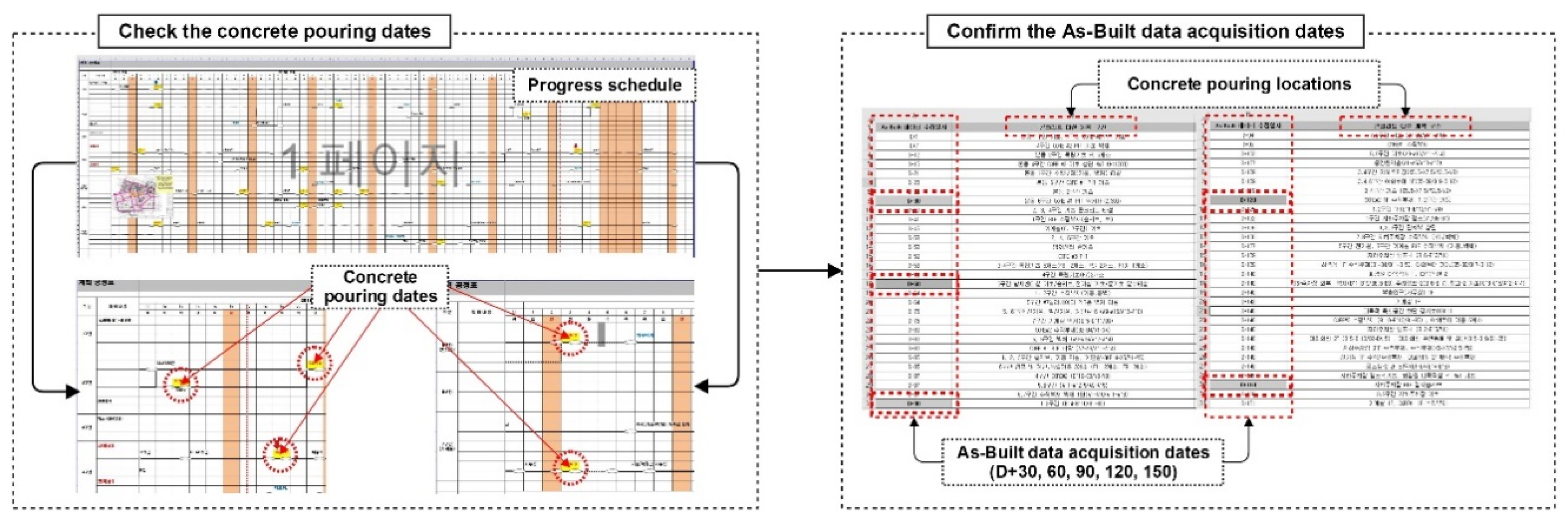
Figure 6.
As-planned 3D view BIM template and the achievement quantity.
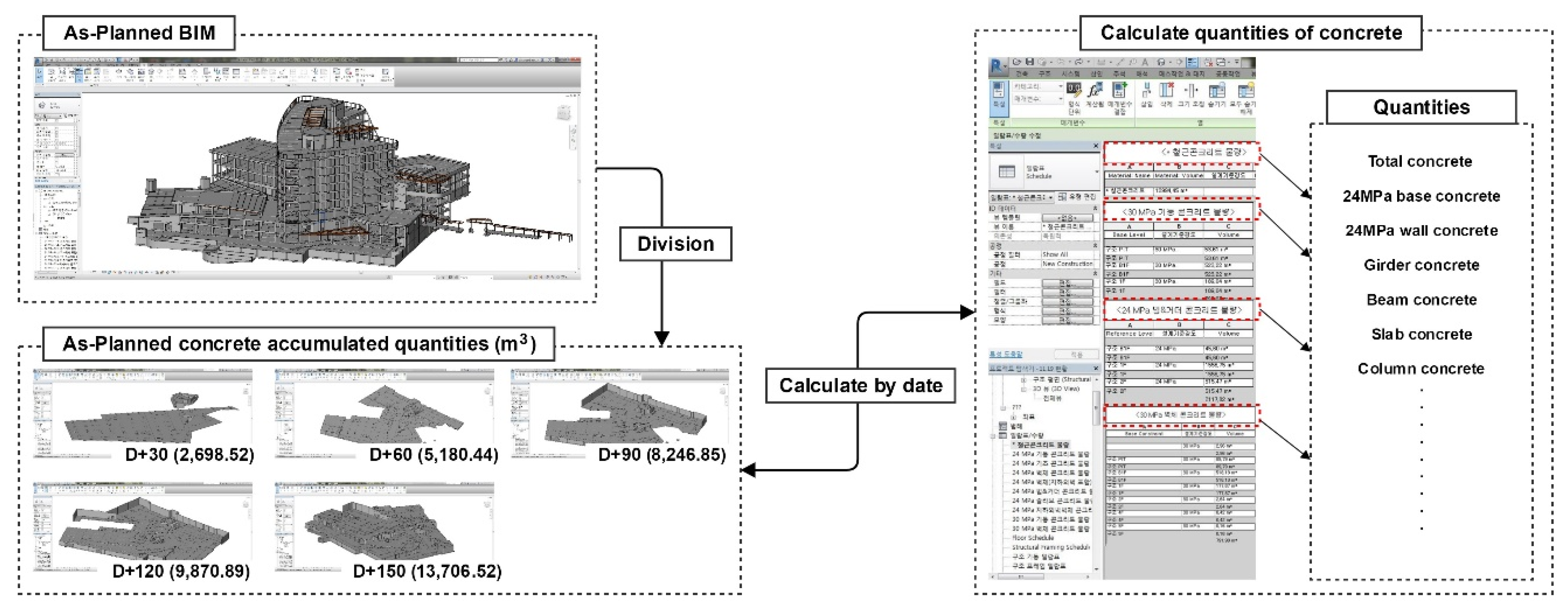
Figure 7.
3D mesh model at each time of the as-built data collection.
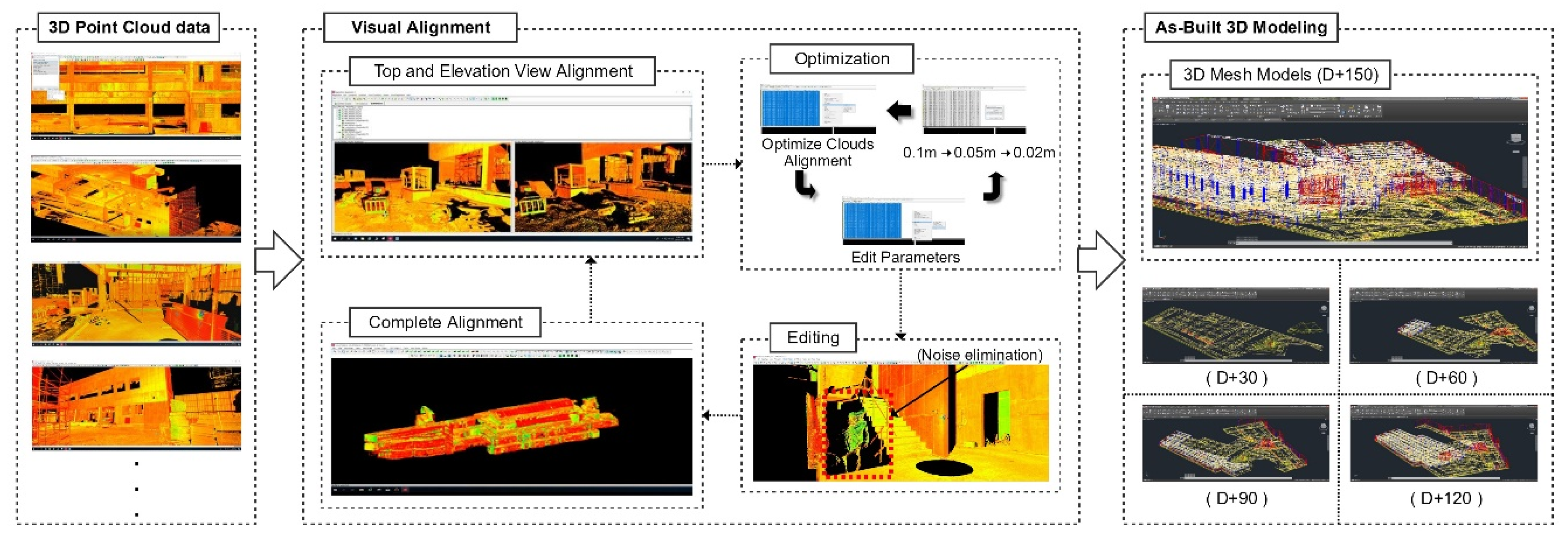
Figure 8.
Example of the quantity calculation of the BIM-based as-built concrete.
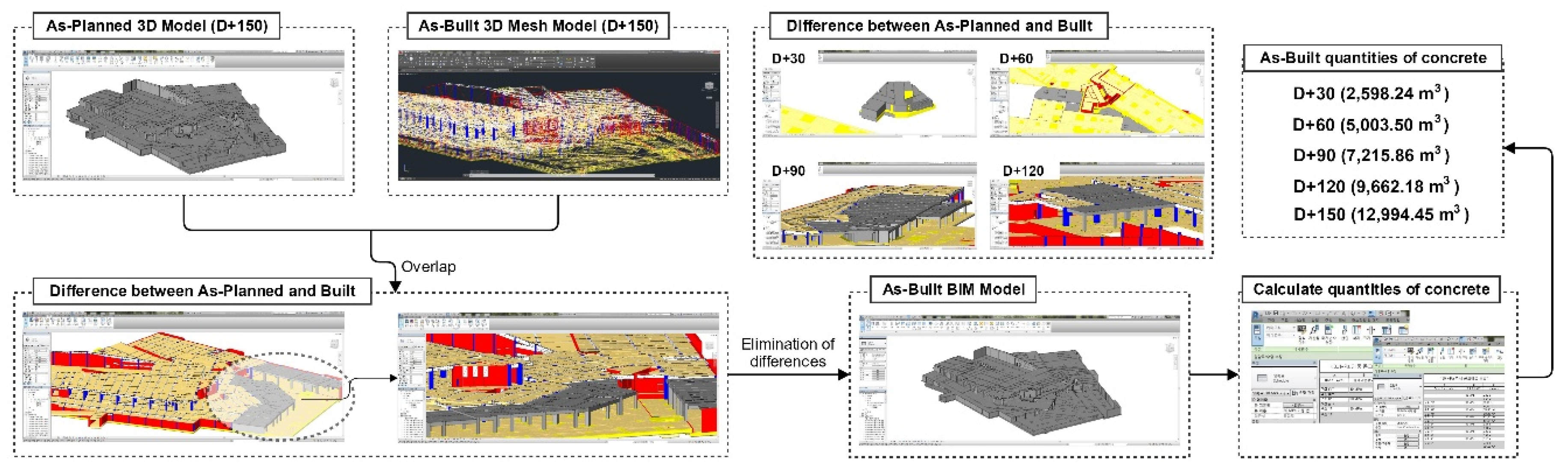
Figure 9.
Project progress evaluation of the case study site.


Table 1.
Target buildings used to acquire point cloud data.
| Scan Type | Scanning Rate | Duration | Acquired Data | |
|---|---|---|---|---|
| Building A | LIDAR/drone | 50 scans/209 images | 6 h/30 min | Column, girder, beam, slab |
| Building B | LIDAR | 30 scans | 3 h | |
| LIDAR (Leica BLK 360): | ||||
| Range: 0.6–60 m, camera system: 15 Mpixel, max resolution: 6 mm @ 10 m, scan speed: 360,000 pts/sec, ranging accuracy: 4 mm @ 10m. | ||||
| Drone and camera (DJI Inspire 2, ZENMUSE X4S): Sensor: CMOS, 1”, effective pixels: 20 MP, lens: F/2.8–11, 8.8 mm, FOV: 84°, Photo resolution: 3:2 (5472 × 3648), 4:3 (4864 × 3648), and 16:9 (5472 × 3078). | ||||
Table 2.
Errors of LIDAR/drone-based point cloud data.
| Measured Distance (m) | Scanning Distance (m) | Average Error (m) | |||
|---|---|---|---|---|---|
| LIDAR | Building A | External width | 29.28, 6.62, 10.45 | 29.289, 6.608, 10.465 | 0.011 |
| Distance between columns | 7.53, 6.67, 1.48 | 7.547, 6.673, 1.495 | 0.012 | ||
| Column height | 2.76 | 2.779 | 0.019 | ||
| Building B | External width | 35.81, 18.49, 8.08 | 35.829, 18.491, 8.098 | 0.012 | |
| Distance between columns | 3.09, 3.09, 3.02 | 3.115, 3.097, 3.021 | 0.011 | ||
| Column height | 6.25, 6.71 | 6.261, 6.724 | 0.012 | ||
| Drone | Building A | External width | 29.28, 6.62, 10.45 | 28.173, 6.638, 10.46 | 0.378 |
| Distance between columns | 7.25, 2.85, 5.46 | 6.651, 2.839, 4.994 | 0.358 | ||
| Column height | 2.76 | 2.688 | 0.072 |
Table 3.
The difference in the input quantity (as-planned, as-built, and actual input quantity).
| Accumulated Quantities of Concrete (m3) | Quantity Difference of Concrete (m3) | ||||
|---|---|---|---|---|---|
| 1. As-Planned | 2. As-Built | 3. Ready-Mixed Concrete Invoice | Difference of Progress (1–2) | Difference of Actual Input Quantity (2–3) | |
| D + 30 | 2698.52 | 2598.24 | 2616 | 100.28 | 17.76 |
| D + 60 | 5180.44 | 5003.50 | 5012 | 176.94 | 8.5 |
| D + 90 | 8246.85 | 7215.86 | 7226 | 1030.99 | 10.14 |
| D + 120 | 9870.89 | 9662.18 | 9659 | 208.71 | 3.18 |
| D + 150 | 13,706.52 | 12,994.45 | 13,003 | 712.07 | 8.55 |
© 2020 by the authors. Licensee MDPI, Basel, Switzerland. This article is an open access article distributed under the terms and conditions of the Creative Commons Attribution (CC BY) license (http://creativecommons.org/licenses/by/4.0/).
Share and Cite
MDPI and ACS Style
Kim, S.; Kim, S.; Lee, D.-E. 3D Point Cloud and BIM-Based Reconstruction for Evaluation of Project by As-Planned and As-Built. Remote Sens. 2020, 12, 1457. https://doi.org/10.3390/rs12091457
AMA Style
Kim S, Kim S, Lee D-E. 3D Point Cloud and BIM-Based Reconstruction for Evaluation of Project by As-Planned and As-Built. Remote Sensing. 2020; 12(9):1457. https://doi.org/10.3390/rs12091457
Chicago/Turabian StyleKim, Seungho, Sangyong Kim, and Dong-Eun Lee. 2020. "3D Point Cloud and BIM-Based Reconstruction for Evaluation of Project by As-Planned and As-Built" Remote Sensing 12, no. 9: 1457. https://doi.org/10.3390/rs12091457
Note that from the first issue of 2016, this journal uses article numbers instead of page numbers. See further details here.