
Phase Centre Corrections of GNSS Antennas and Their Consistency with ATX Catalogues


1
Department of Construction Materials Engineering and Geoengineering, Faculty of Civil Engineering and Architecture, Lublin University of Technology, 20-618 Lublin, Poland
2
Department of Integrated Geodesy and Cartography, AGH University of Science and Technology, 30-059 Krakow, Poland
3
Joint International Tourism College, Hainan University—Arizona State University, Haikou 570228, China
4
UNESCO Department for Ecological Awareness and Sustainable Development, Faculty of Ecology and Environmental Sciences, Technical University in Zvolen, 960 01 Zvolen, Slovakia
*
Author to whom correspondence should be addressed.
Remote Sens. 2022, 14(13), 3226; https://doi.org/10.3390/rs14133226
Submission received: 6 June 2022
/
Revised: 1 July 2022
/
Accepted: 2 July 2022
/
Published: 5 July 2022
(This article belongs to the Special Issue GNSS, Space Weather and TEC Special Features)
Abstract
:Changes of the antenna models on permanent global navigation satellite system (GNSS) stations can lead to jumps and discontinuities in the coordinate time series. In this paper, the results of research on the adequacy of the antenna phase centre corrections (PCC) variations are presented by analysing its component—the antennas’ phase centre offset (PCO). For this purpose, height differences were determined using different and independent methods: EUREF Permanent Network (EPN) combined solutions, Precise Point Positioning (PPP), and the single baseline solution. The results of GNSS processing were referenced to direct geometric levelling outputs. The research was conducted only within the global positioning system (GPS) system due to the compatibility of one of the receivers, and the experiment was based on a comparison of the height differences between four GNSS antennas located on the roof of a building: two permanent station antennas and two auxiliary points. The antennas were located at similar heights; precise height differences were determined by geometric levelling, both at the beginning and the end of the session. Post-processing was conducted with the use of the GPS system, precise ephemeris, the adopted antenna correction model, and a zero-elevation mask. For one of the antennas, a change of the antenna characteristic model from IGS08 to IGS14 leads to an 8-mm difference in height. Older antennas used in the national (or transnational) permanent network need individual PCC.
1. Introduction
The correct calibration of global navigation satellite system (GNSS) antennas is the basis for precise satellite positioning and plays a key role in many aspects of positioning and navigation [1,2]. In general, GNSS antennas have a well-defined antenna phase centre (APC, Figure 1) and should be described by the azimuth (α) and elevation (β) functions [3]. The APC determined by phase centre variation (PCV) is a shift in position depending on the observed elevation angle and azimuth with regards to the satellite [4]. The antenna reference point (ARP) is a physical point where the antenna height above the physical point is measured [5]. The antenna phase centre offset (PCO) is the difference between the ARP and the mean electrical APC defined by the intersection of the vertical antenna axis of symmetry with the bottom of the antenna [6]. The combination of PCO and PCV is called phase centre corrections (PCC).
Depending on the accuracy and quality of solutions needed to be achieved, absolute and relative antenna calibration models are used. For many years, relative phase centre corrections were made based on measurements on a short baseline referred to as a reference antenna (The Dorne Margolin T of Allen Osborne Associates antenna—AOAD/M_T), with the arbitrary assumption that the PCV of the reference antenna is zero [7,8]. Absolute correction for an antenna can be obtained either by measurement in an anechoic chamber [9] or by field measurements on a short baseline using a robot mount [10].
As the research shows, the problem of the antenna calibrations is not new, but it still experiences issues with proper assumptions regarding calibrations and the correctness of calculations. Different antenna calibration models impact, among other things, estimated station positions. Some empirical research tests show a relative vertical offset exists with the same model of antennas of up to 1 mm, while horizontal offsets are negligible [11]. The research conducted by Baire et al. showed agreement to the level of 2 mm in the case of horizontal offsets and 5 mm in the case of the height component based on daily static Precise Point Positioning (PPP) sessions [3]. A variety of studies have been conducted for the establishment of new calibration methods, e.g., [11,12,13,14]. The differences in model calibrations between the robot and anechoic chamber have an impact on the coordinates: up to +/− 2 mm for the horizontal and +/− 10 mm for the height component [15]. Over 10 mm of the height component difference occurs when individual antenna corrections by GEO++ are comparable to igs08.atx [16]. Moreover, in specific conditions, it is worth considering the impact of other environmental phenomena, such as multipath interference [17,18], antenna mounting [19,20], the near-field effect, or seasonal snow cover [21]. Analyses performed for EUREF permanent network (EPN) stations show that the change to the new catalogue of absolute calibration models (from IGS08.ATX to IGS14.ATX) might have an impact on stations’ coordinates. Phase centre corrections (PCC) are an integral part of high accuracy GNSS applications [22]. The research showed on more than 40 PCC models that the magnitudes of the PCO shifts among different versions of the antenna files (Antex) were above 1 mm [23]. The differences between the antenna model (mean) and the individual PCC may cause a discrepancy of 10 mm for the horizontal and vertical components, but this does not usually exceed 2 mm for the horizontal and 4 mm for the vertical ones [24].
Based on this knowledge, an analysis of the selected antenna models, TRM57971.00 NONE and ASH70195C_M SNOW, was performed. These antennas are used on EPN’s KRA1 (TRM57971.00 NONE) and KRAW (ASH70195C_M SNOW) stations (Kraków, Poland). The stations are located close to each other (3.5 m), which is a convenient situation for the verification of their individual characteristics by comparison to the catalogue ones. The study consisted of several analyses. The first was focused on differences of the studied models in the igs08.atx and igs14.atx catalogues. The second was the difference in height between the antenna ARP, as calculated by different satellite methods. Additionally, height differences were referenced to the auxiliary stations (KR01 and KR02) and to precise spirit levelling. The third analysis gathered archival material based on several experiments that have been conducted since 2011.
2. Methods
The paper is focused on the changes of the ellipsoid height, which are measured to the ARP. The height and the horizontal component are revealed in the current international terrestrial reference frame (ITRF2014). Along with the reference frame change, GNSS receiver antenna calibration models are also changed to be consistent with the current realisation of the frame. In the epoch under analysis, the International GNSS Service (IGS) provided data on 316 GNSS permanent stations. After the introduction of the ITRF2014, 113 of these changed their reported heights due to the antenna calibration parameter changes. The values of the estimated height offset are shown in Figure 2, which are based on IGS data.
As an example, the difference between the I08.ATX and I14.ATX calibration models for the TRM57971.00 NONE antenna is shown in Figure 3. The −1.8-mm PCO difference for the G01 (GPS L1) frequency and high PCV elevation dependent differences for the R01 (GLONASS L1) frequency are clearly seen.
Figure 4 shows PCV variations of the TRM57971.00 NONE antenna between the ATX08 and ATX14 antenna models for two (G01 and G02) GPS signal frequencies. Azimuth elevation differences vary from −1.5 mm to 1.5 mm. The largest differences are in the northwest vs. southeast directions, which are up to 1.5 mm, while, in the perpendicular direction (northeast vs. southwest), the situation is the opposite, with a difference of up to −1.5 mm. Such maximum differences appear only for the nearest-to-horizon satellites, which have the smallest impact on the GNSS processing due to weighting. Differences for satellites with the highest elevation (located in the centre of the circles) are close to 0.
In general, changes in the station heights mean that the antenna model changes or suggests an inaccurate calibration model of the antenna’s PCO or/and PCV. Detailed research has been performed for the ASH701945_C antenna. This type of the antenna, with various domes, is still used at stations including IENG, KELY (NONE), BOGI, KRAW (SNOW), and SKEO (OSOD). The ASH701945C_M SNOW antenna was calibrated by Geo++ GmbH on 25 March 2011 with the use of a single antenna [4]. Six others had individual calibrations, not KRAW or BOGI. It is possible that the antenna used at the KRAW station has distinctive characteristics other than those determined by Geo++. To check on this, an experiment on the KRAW antenna was conducted. In contrast to robot or anechoic chamber experiments, the authors used an analysis of the short baselines between the different permanent (KRAW and KRA1) and auxiliary stations (KR01 and KR02).
3. KRAW and KRA1 Stations
The pair of antennas KRAW and KRA1 are located on a five-storey university building about 3.5 m away from each other. This is an unusual circumstance, which is beneficial for GNSS networks [25], but very few permanent reference stations are located in this way. The oldest station KRAW has continuously collected data since the end of 2002, while the younger KRA1 has been collecting data since 2010 [26]. In 2005, the characteristics of the gravity field (acceleration and gradient) were measured for the KRAW station, and a station normal height was determined [27]. Up to 2018 to 2019, the station’s equipment did not change (brand and model). The KRAW used an Ashtech UZ-12 receiver with an ASH70195C_M SNOW antenna. In 2019, a new receiver was introduced, a LEICA RX1200 GGPRO (without changing the antenna). The KRA1 uses a Trimble NETR5 receiver with a TRM57971.00 NONE antenna. In 2018, the KRA1 antenna was replaced by another TRM57971.00 NONE model with individual PCC. For the KRAW station, the ASH70195C_M SNOW antenna was not calibrated individually.
During the experiments on quasi-geoid modelling, it was found that the antenna’s calibrations might be inaccurate [28]. It was suspected that the ellipsoidal height difference between the stations is of the opposite sign to their coordinates in the EPN network [29]. To verify this situation, a test survey was organised. It was based on a comparison of the height differences between the stations (KRAW and KRA1) and temporary stations KR01 and KR02 (with TRM57971.00 NONE antennas), as well as an analysis of the archival data. The Trimble antennas at KR01 and KR02 are commonly used in GNSS permanent networks. Exactly the same type was tested at Wuhan University by the absolute method (the field robot); the test showed the high repeatability of the obtained calibrations: σN = 0.17 mm, σE = 0.12 mm, and σU = 0.30 mm [12]. The same model of antennas on KRA1, KR01, and KR02 guaranteed that the impact of the differences between the antennas would not be significant. The only difference was the power supply system (different model). The antennas were located at similar height levels, with a distance of about 3.5 m from each other (Figure 5).
The observation sessions took place over 12 days in December 2016. The precise differences in height were defined by GPS post-processing. As the height difference reference value, the results of geometric levelling (Zeiss KoNi 007) were used. The levelling was conducted both at the beginning and the end of the GPS session.
4. Results
The difference in heights between KRAW, KRA1, KR01, and KR02 was calculated by post-processing of the observations. Due to the KRAW Ashtech UZ-12 receiver capability, only the GPS system was used. Post-processing was based on the final IGS orbits, the igs08.atx antenna corrections model, and a zero-elevation mask. Height differences obtained from precise levelling were compared with those derived from EPN-combined solutions, PPP calculated with Bernese GNSS Software (BGS) [30], Nevada Geodetic Laboratory (NGL, [31]), a network solution, a single baseline solution (GNSS Solutions 3.80.8, Trimble Business Centre 3.50), and other archive materials. In GNSS Solutions, only the elevation-dependent PCV version of the antenna characteristics was used.
Height differences obtained from precise levelling and GNSS solutions showed several discrepancies. Height differences between the KRA1 antenna reference point and the three other measured stations (KRAW, KR01, and KR02) from GNSS post-processing are affected by the inaccuracy of the antenna PCO and PCV. The analysis shows that the height of the KRAW station antenna (ASH70195C_M SNOW) from GNSS processing (EPN combined and PPP solutions) is 16 mm too high in comparison to the levelling results (Figure 6). This may indicate the inadequacy of the ASH70195C_M SNOW calibration data. A lower disagreement was obtained in the case of the TRM57971.00 NONE antenna (KR01 and KR02 stations). This discrepancy was about 5 mm for PPP solutions and 2 mm for network solutions. The differences obtained by single baseline solutions using the Trimble Business Centre (TBC) and GNSS Solution engineering software show far fewer discrepancies, not exceeding 0.4 mm. This is due to the very short baseline between the measured points.
The height difference of KRAW–KRA1 was calculated based on the EPN weekly combined SINEX (Software INdependent Exchange format) solutions from 2010 to 2016 (1564 to 1877 GPS weeks, Figure 7). During weeks when igs08 and igb08 were in use, there were some inaccurate solutions, which may be treated as gross errors. Despite that, clearly visible is the change in ellipsoidal height difference after the introduction of the IGS14 system (after GPS week 1933 [33]). The offset is up to about 8 mm (Figure 7). It is surprising that, during the short time between the introduction of the IGS14 system and individual phase corrections for the KRA1 antenna (week 1986), the height difference was closest to levelling (−0.5 mm) from any network calculation.
Alternatively, an independent PPP calculation was used—the Nevada Geodetic Laboratory (NGL). The facility provides permanent, fully, and freely available PPP results based on globally distributed permanent GNSS station data. Based on these data, the ellipsoidal height differences between station KRAW and KRA1 for the period 2009.7–2022.0 GPS weeks 1569–2190) were analysed (Figure 8). The results showed a mean difference +1.83 mm (green line) and were compared to precise geometric levelling −6.2 mm (red line). Both data provided inaccurate results, which was not a surprise, as they were based on the different antenna characteristics (IGS Antex files) of the KRAW antenna.
The archival materials regarding the height differences between the KRAW–KRA1 stations consist of: two independent sets of post-processing results from 2008 to 2011 calculated during the Polish integration of the base geodetic network with reference permanent stations ASG-EUPOS (BGS), EPN combined solutions 2013–2014, PPP (BGS) 2012–2014, and the post-processing of various short GPS observations (Trimble Business Centre 3.50—TBC) 2011–2016 (Table 1). The short GPS observations consist of various 4-h, 8-h, and 12-h sessions, the calculations of which were also checked in GNSS Solutions 3.80.3 and Geonet 2006 software [29]. The differences between them are negligible, which allows us to show a single (mean) value achieved by the most often-used software. The compatibility of the short observation post-processing (TBC, GNSS Solutions, or Geonet 2006) and spirit levelling (−6.2 mm) results is noticeable when the more sophisticated solutions (e.g., PPP network solutions) give opposite values. The most contrary are values from PPP (BGS) 2012–14; the differences in the levelling result were as much as 20 mm. All of them used IGS08 antenna characteristics or only the elevation-dependent PCV model (GNSS Solutions). Surprisingly, such popular “engineering” software (e.g., TBC) achieved better results, comparable to spirit levelling, than the BGS (both short baseline calculations and PPP). The origin of the advantage of this type of software is not clear. It is probably that, for very close stations, the single baseline solutions, based only on the L1 frequency, give better results.
5. Discussion
Modern manufactured antennas are of better repeatability than older models, i.e., exhibiting less deviation from the pattern (average) in antex files. This is the case for, e.g., the Trimble Zephyr Geodetic 2 (TRM57971.00 NONE) antenna used in the experiment. In selected stations (e.g., KRAW and BOGI), antennas are still being used that date back to the 1990s. Their characteristics may differ from the accepted standards. Therefore, it can be postulated that individual characteristics should be developed for them, so that they do not introduce errors to the network in which they work (IGS, EPN, etc.). However, their individual calibrations are a matter of debate due to costs.
We checked the KRAW station based on a KRA1–KRAW overpass survey and the additional temporary stations KR01 and KR02. Archival materials from various authors were also collected. As a result of the analysis of these materials, it can be stated that the antenna (Ashtech ASH70195C_M SNOW) of the KRAW station has different characteristics from those revealed in the IGS files of the subsequent versions. Azimuth elevation is mostly dependent on the lowest-over-horizon satellites [4,37], which have the smallest weights in processing. Thus, this aspect has the smallest impact. PPP processing shows a systematic shift in the KRAW–KRA1 height difference at the level of +1.8 mm, while measurements directly from levelling show a −6.2-mm difference. This may result in incorrect altitude results and have an adverse effect on, e.g., fitting the global geopotential model into the national height frame. Therefore, old stations that are included in the national (or transnational) permanent network need individual PCC. The tested network solutions, both PPP and baseline solutions [34,35], were not resistant to the impact of real KRAW antenna characteristics, different from any analysed ATX catalogue. As a result, the permanent stations’ ellipsoid heights in network solutions may be subject to systematic errors. Even using advanced and renowned software (Bernese GNSS Solutions), such errors cannot be detected. The analysis showed that a calculation strategy based on a short baseline L1-only solution may detect the error, even if the popular “engineering” software is used (Trimble Business Centres, GNSS Solutions, Geonet).
The question arises as to what the optimal solution for old antennas is—the determination of individual characteristics (PCC) or replacement with a new antenna (also with individual PCC). In other words, should the old stations be partially or fully modernized? For the analysed station KRAW (antenna ASH70195C_M SNOW), a full upgrade had the advantage of introducing four GNSS systems compared to the existing GPS-only. Especially, introduction of the Galileo system may benefit the station solution [38,39], e.g., decreasing the positioning error statistics for GPS + Galileo combinations [40] despite Galileo still not providing the same satellite availability as GPS [41]. Concluding the results and achievements in the investigation of PCC by other authors [16,19,21,24], we are inclined to say that the time of antennas from the 1990s should be completed and full modernization carried out, despite the higher costs.
Author Contributions
Conceptualization, L.B.; methodology, L.B. and J.K.; software, L.B. and J.K.; validation, L.B., J.K. and K.M.; formal analysis, L.B., J.K. and K.M.; investigation, L.B., J.K. and K.M.; resources, L.B. and J.K.; data curation, L.B. and J.K.; writing—original draft preparation, L.B., J.K. and K.M.; writing—review and editing, L.B., J.K., K.M., M.S. and B.K.; visualization, L.B., J.K., B.K. and K.M.; supervision, L.B., J.K., K.M. and M.S.; project administration, L.B.; and funding acquisition, L.B., J.K., M.S., B.K. and K.M. Percentage contributions: L.B., 60%; J.K., 15%; B.K., 5%; M.S., 5%; and K.M., 15%. All authors have read and agreed to the published version of the manuscript.
Funding
This work was funded by the Initiative for Excellence Research University grant from the AGH University of Science and Technology, by research subvention no. 16.16.150.545, and by the National Science Centre as part of MINIATURA 5, application no. 2021/05/X/ST10/00058. This work was supported by the grant VEGA 1/0736/21 of the Scientific Grant Agency of the Ministry of Education Science Research and Sport of the Slovak Republic and the Slovak Academy of Sciences.
Data Availability Statement
Not applicable.
Conflicts of Interest
The authors declare no conflict of interest.
References
- Specht, M.; Specht, C.; Dąbrowski, P.; Czaplewski, K.; Smolarek, L.; Lewicka, O. Road tests of the positioning accuracy of INS/GNSS systems based on MEMS technology for navigating railway vehicles. Energies 2020, 13, 4463. [Google Scholar] [CrossRef]
- Specht, C.; Specht, M.; Dąbrowski, P. Comparative analysis of active geodetic networks in poland. In Proceedings of the 17th International Multidisciplinary Scientific GeoConference SGEM 2017, Vienna, Austria, 27–29 November 2017. [Google Scholar]
- Baire, Q.; Bruyninx, C.; Legrand, J.; Pottiaux, E.; Aerts, W.; Defraigne, P.; Bergeot, N.; Chevalier, J.M. Influence of different GPS receiver antenna calibration models on geodetic positioning. GPS Solut. 2014, 18, 529–539. [Google Scholar] [CrossRef]
- Dawidowicz, K. Comparison of Using Relative and Absolute PCV Corrections in Short Baseline GNSS Observation Processing. Artif. Satell. 2011, 46, 19–31. [Google Scholar] [CrossRef] [Green Version]
- Hofmann-Wellenhof, B.; Lichtenegger, H.; Wasle, E. GNSS—Global Navigation Satellite Systems; Springer: Vienna, Austria, 2008; ISBN 978-3-211-73012-6. [Google Scholar]
- Luo, X. Mathematical Models for GPS Positioning. In GPS Stochastic Modelling; Springer Theses; Springer: Berlin/Heidelberg, Germany, 2013; pp. 55–116. ISBN 978-3-642-34835-8. [Google Scholar]
- Breuer, B.; Campbell, J.; Görres, B.; Hawig, R.; Wohlleben, R. Kalibrierung von GPS-Antennen für hochgenaue geodätische Anwendungen. Z. Satell. Position. Navig. Kommun. 1995, 2, 49–59. [Google Scholar]
- Schmid, R.; Dach, R.; Collilieux, X.; Jäggi, A.; Schmitz, M.; Dilssner, F. Absolute IGS antenna phase center model igs08.atx: Status and potential improvements. J. Geod. 2016, 90, 343–364. [Google Scholar] [CrossRef] [Green Version]
- Schupler, B.R.; Clark, T.A. How different antennas affect the GPS observable. GPS World 1991, 2, 32–36. [Google Scholar]
- Görres, B.; Campbell, J.; Becker, M.; Siemes, M. Absolute calibration of GPS antennas: Laboratory results and comparison with field and robot techniques. GPS Solut. 2006, 10, 136–145. [Google Scholar] [CrossRef]
- Daneshmand, S.; Sokhandan, N.; Zaeri-Amirani, M.; Lachapelle, G. Precise calibration of a GNSS antenna array for adaptive beamforming applications. Sensors 2014, 14, 9669–9691. [Google Scholar] [CrossRef] [Green Version]
- Hu, Z.; Zhao, Q.; Chen, G.; Wang, G.; Dai, Z.; Li, T. First Results of Field Absolute Calibration of the GPS Receiver Antenna at Wuhan University. Sensors 2015, 15, 28717–28731. [Google Scholar] [CrossRef] [Green Version]
- Filler, V.; Kostelecký, J. GPS antenna calibration at the Geodetic Observatory Pecny, Czech Republic. Rep. Geod. Geoinform. 2001, 1, 233–244. [Google Scholar]
- Bergstrand, S.; Jarlemark, P.; Herbertsson, M. Quantifying errors in GNSS antenna calibrations: Towards in situ phase center corrections. J. Geod. 2020, 94, 1–15. [Google Scholar] [CrossRef]
- Krzan, G.; Dawidowicz, K.; Wielgosz, P. Antenna phase center correction differences from robot and chamber calibrations: The case study LEIAR25. GPS Solut. 2020, 24, 44. [Google Scholar] [CrossRef] [Green Version]
- Araszkiewicz, A.; Kiliszek, D.; Podkowa, A. Height variation depending on the source of antenna phase centre corrections: LEIAR25.R3 case study. Sensors 2019, 19, 4010. [Google Scholar] [CrossRef] [PubMed] [Green Version]
- Li, L.; Li, B.; Chen, H.; Wang, F. Multipath Effect on Phase Center Calibration of GNSS Antenna. In China Satellite Navigation Conference (CSNC) 2015 Proceedings: Volume III; Sun, J., Liu, J., Fan, S., Lu, X., Eds.; Springer: Berlin/Heidelberg, Germany, 2015; pp. 259–268. [Google Scholar]
- Rovera, G.D.; Abgrall, M.; Uhrich, P.; Defraigne, P.; Bertrand, B. GNSS antenna multipath effects. In Proceedings of the 2018 European Frequency and Time Forum (EFTF), Turin, Italy, 10–12 April 2018; pp. 208–212. [Google Scholar]
- Dawidowicz, K.; Krzan, G.; Baryła, R.; Swiatek, K. The Impact of GNSS Antenna Mounting during Absolute Field Calibration on Phase Center Correction—JAV_GRANT-G3T Antenna Case Study. In Proceedings of the 10th International Conference “Environmental Engineering, Vilnius, Lithuania, 27–28 April 2017; pp. 27–28. [Google Scholar]
- Echeverri, J.M.Q.; Pareja, T.F.; De Vicente y Oliva, J. Effectiveness of centering devices of geomatics instruments. Procedia Manuf. 2019, 41, 437–444. [Google Scholar] [CrossRef]
- Kostelecký, J. On determination of GPS antenna phase centres at the geodetic observatory Pecny. Reports Geod. 2002, 1, 145–152. [Google Scholar]
- Breva, J.; Kröger, J.; Kersten, T.; Schön, S. Validation of phase center corrections for new GNSS signals obtained with absolute antenna calibration in the field. In Proceedings of the EGU General Assembly 2019, Vienna, Austria, 7–12 April 2019; p. 14143. [Google Scholar]
- Zhou, R.; Hu, Z.; Zhao, Q.; Cai, H.; Liu, X.; Liu, C.; Wang, G.; Kan, H.; Chen, L. Consistency Analysis of the GNSS Antenna Phase Center Correction Models. Remote Sens. 2022, 14, 540. [Google Scholar] [CrossRef]
- Araszkiewicz, A.; Völksen, C. The impact of the antenna phase center models on the coordinates in the EUREF Permanent Network. GPS Solut. 2017, 21, 747–757. [Google Scholar] [CrossRef]
- Brockmann, E.; Ineichen, D.; Schaer, S. Benefits of double stations in permanent GNSS networks. In Proceedings of the EGU General Assembly Conference Abstracts, Vienna, Austria, 7–12 April 2013; EUREF: Budapest, Hungary, 2013. [Google Scholar]
- Kudrys, J. Permanent GNSS Observations at AGH-UST Satellite Observatory. Rep. Geod. Geoinform. 2016, 100, 101–107. [Google Scholar] [CrossRef] [Green Version]
- Banasik, P. Wyznaczenie wysokości normalnej i charakterystyk pola cieżkościowego dla stacji permanentnej KRAW. Geomat. Environ. Eng. 2007, 1, 53–60. [Google Scholar]
- Borowski, Ł. Determination of normal heights of ASG-EUPOS stations illustrated with an example od KRAW station. In 4th Doctoral Seminar on Geodesy and Cartography; Biryło, M., Ed.; Wydawnictwo UWM: Olsztyn, Poland, 2012; pp. 19–25. ISBN 978-83-7299-766-1. [Google Scholar]
- Borowski, Ł. Zastosowanie Sieci ASG-EUPOS Do Modelowania Lokalnej Quasi-Geoidy. Ph.D. Thesis, AGH University of Science and Technology, Krakow, Poland, 2015. [Google Scholar]
- Dach, R.; Lutz, S.; Walser, P.; Fridez, P. Bernese GNSS Software Version 5.2; University of Bern, Bern Open Publishing: Berne, Switzerland, 2015; Volume 47, ISBN 1879621142. [Google Scholar]
- Blewitt, G.; Hammond, W.; Kreemer, C. Harnessing the GPS Data Explosion for Interdisciplinary Science. Eos 2018, 99, 485. [Google Scholar] [CrossRef]
- Borowski, Ł.; Kudrys, J. Adequacy of GNSS antenna calibration model—Case study Abstract. In Proceedings of the EUREF 2017 Symposium, Wrocław, Poland, 17–19 May 2017. [Google Scholar]
- Dawidowicz, K. IGS08.ATX to IGS14.ATX change dependent differences in a gnss-derived position time series. Acta Geodyn. Geomater. 2018, 15, 363–378. [Google Scholar] [CrossRef] [Green Version]
- Liwosz, T.; Rogowski, J.; Kruczyk, M.; Rajner, M.; Kurka, W. Wyrównanie Kontrolne Obserwacji Satelitarnych Gnss Wykonanych na Punktach Asg-Eupos, Euref-Pol, Euvn, Polref i Osnowy i Klasy Wraz z Oceną Wyników; Warsaw Univeristy of Technology: Warsaw, Poland, 2011. [Google Scholar]
- Jaworski, L. Sprawozdanie Techniczne IV Etapu Kampani Integracyjnej—Opracowanie i Wyrównanie Obserwacji GNSS; Centrum Badań Kosmicznych PAN: Warszawa, Poland, 2011. [Google Scholar]
- Military University of Technology EPN Analysis Coordination Center. Available online: http://www.gnss.wat.edu.pl/ (accessed on 15 June 2022).
- Bassa, C.G.; Hainaut, O.R.; Galadí-Enríquez, D. Analytical simulations of the effect of satellite constellations on optical and near-infrared observations. Astron. Astrophys. 2022, 657, A75. [Google Scholar] [CrossRef]
- Mikoś, M.; Nowak, A.; Lackowski, M.; Sośnica, K. Wkład systemu satelitarnego Galileo w rozwój geodezji. Przegląd Geod. 2022, 1, 23–26. [Google Scholar] [CrossRef]
- Maciuk, K. Advantages of Combined GNSS Processing Involving a Limited Number of Visible Satellites. Sci. J. Sil. Univ. Technol. Ser. Transp. 2018, 98, 89–99. [Google Scholar] [CrossRef]
- Prochniewicz, D.; Wezka, K.; Kozuchowska, J. Empirical stochastic model of multi-GNSS measurements. Sensors 2021, 21, 4566. [Google Scholar] [CrossRef] [PubMed]
- Prochniewicz, D.; Grzymala, M. Analysis of the impact of multipath on Galileo system measurements. Remote Sens. 2021, 13, 2295. [Google Scholar] [CrossRef]
Figure 1.
A phase shift due to antenna model change.

Figure 2.
Height offset due to antenna model changes; red marks indicate positive height changes, blue marks indicate negative changes, and white indicates that no changes occurred. The ‘whiskers’ show the amount of height offset.
Figure 2.
Height offset due to antenna model changes; red marks indicate positive height changes, blue marks indicate negative changes, and white indicates that no changes occurred. The ‘whiskers’ show the amount of height offset.

Figure 3.
PCO and PCV difference between I08.ATX and I14.ATX calibration data for the TRM57971.00 NONE antenna.
Figure 3.
PCO and PCV difference between I08.ATX and I14.ATX calibration data for the TRM57971.00 NONE antenna.

Figure 4.
PCV variations between ATX08 and ATX14 for two GPS signal frequencies for the TRM57971.00 NONE antenna.
Figure 4.
PCV variations between ATX08 and ATX14 for two GPS signal frequencies for the TRM57971.00 NONE antenna.

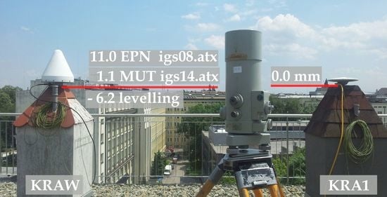
Figure 5.
Location of the KRAW and KRA1 permanent stations on the roof of the AGH-UST buildings with the temporary KR01 and KR02 stations.
Figure 5.
Location of the KRAW and KRA1 permanent stations on the roof of the AGH-UST buildings with the temporary KR01 and KR02 stations.

Figure 6.
Differences between the heights obtained with PPP and a network solution (left) and single baseline solutions (right) [32].
Figure 6.
Differences between the heights obtained with PPP and a network solution (left) and single baseline solutions (right) [32].

Figure 7.
The time series for the height difference between KRAW–KRA1 calculated by EPN on the basis of several antenna correction catalogues (IGS ATX files) [32].
Figure 7.
The time series for the height difference between KRAW–KRA1 calculated by EPN on the basis of several antenna correction catalogues (IGS ATX files) [32].

Figure 8.
Height difference between KRA1–KRAW from NGL–PPP (navy dots), systematic difference from levelling −6.2 mm (red line), and mean difference 1.83 mm (green line) [31].
Figure 8.
Height difference between KRA1–KRAW from NGL–PPP (navy dots), systematic difference from levelling −6.2 mm (red line), and mean difference 1.83 mm (green line) [31].

Figure 9.
Height difference between KRA1 and KRAW from the levelling from 2011 to 2022.

Figure 10.
Height difference (m) between the KRAW and KRA1 antenna reference points from precise levelling.
Figure 10.
Height difference (m) between the KRAW and KRA1 antenna reference points from precise levelling.


Table 1.
Archive values of differences between the KRA1–KRAW stations.
| Archive Data | Δh (mm) | σ (mm) |
|---|---|---|
| Warsaw University of Technology 2008–2011 (BGS) [34] | 5.5 | - |
| PAN Space Research Centre 2008–2011 (BGS) [35] | 7.3 | - |
| EPN Combined Solution 2013–2014 [29] | 11.0 | 1.5 |
| PPP (BGS) 2012–2014 [29] | 14.7 | - |
| Trimble Business Centre 2011–2016 [29] | −6.9 | 0.5 |
| MUT Combined Solutions igs14.atx 2017 [36] | −0.5 | 2.2 |
| MUT * Combined Solutions igs14.atx 2018–2022 (KRA1—individual PCC) [36] | 1.1 | 2.7 |
* Military University of Technology Analysis Coordination Centre.
Publisher’s Note: MDPI stays neutral with regard to jurisdictional claims in published maps and institutional affiliations. |
© 2022 by the authors. Licensee MDPI, Basel, Switzerland. This article is an open access article distributed under the terms and conditions of the Creative Commons Attribution (CC BY) license (https://creativecommons.org/licenses/by/4.0/).
Share and Cite
MDPI and ACS Style
Borowski, L.; Kudrys, J.; Kubicki, B.; Slámová, M.; Maciuk, K. Phase Centre Corrections of GNSS Antennas and Their Consistency with ATX Catalogues. Remote Sens. 2022, 14, 3226. https://doi.org/10.3390/rs14133226
AMA Style
Borowski L, Kudrys J, Kubicki B, Slámová M, Maciuk K. Phase Centre Corrections of GNSS Antennas and Their Consistency with ATX Catalogues. Remote Sensing. 2022; 14(13):3226. https://doi.org/10.3390/rs14133226
Chicago/Turabian StyleBorowski, Lukasz, Jacek Kudrys, Bartosz Kubicki, Martina Slámová, and Kamil Maciuk. 2022. "Phase Centre Corrections of GNSS Antennas and Their Consistency with ATX Catalogues" Remote Sensing 14, no. 13: 3226. https://doi.org/10.3390/rs14133226
Note that from the first issue of 2016, this journal uses article numbers instead of page numbers. See further details here.