
An Image Planar Positioning Method Base on Fusion of Dual-View Airborne SAR Data


College of Electronic Science, National University of Defense Technology (NUDT), Changsha 410073, China
*
Author to whom correspondence should be addressed.
Remote Sens. 2023, 15(10), 2499; https://doi.org/10.3390/rs15102499
Submission received: 9 March 2023
/
Revised: 28 April 2023
/
Accepted: 4 May 2023
/
Published: 9 May 2023
Abstract
:Effective utilization of airborne synthetic-aperture (Airborne SAR) imagery often requires precise location of each image pixel. Historically, the positioning of airborne SAR imagery either relies on the use of reliable reference points to determine the relative position of the image, or requires the precise motion information of the aircraft and the characteristics of the SAR data collection system as input to determine the absolute position of the image. However, for many applications, the accuracy of traditional positioning methods is not high due to the challenge in obtaining the accurate geographic positions of reliable reference points and the inaccuracy of the recorded aircraft motion information. This study introduces an airborne SAR image planar positioning approach based on the premise that the systematic positioning error of the dual-view airborne SAR images are relatively consistent. The suggested planar positioning method applies the positioning auxiliary parameters of the initial ground-range airborne SAR image to ascertain the transformation relationship between the target’s initial geographic position and pixel position, and it then uses the equivalent equation for the position of the homologue point to assess the systematic positioning error of the SAR image and determine the geographic position of a pixel in a digital SAR image. This approach has advantages over previous techniques in that it requires no precise geographic position information of the ground reference points, and on the basis of using the RD model to accomplish coarse positioning of four corners of SAR image, it no longer needs aircraft trajectory data. Tests were conducted using two airborne SAR images actually captured, and the experimental results indicate that the proposed method can achieve high precision planar positioning of dual-view airborne SAR images. Error sources are analyzed and recommendations are given to improve image positioning accuracy in future airborne SARs.
1. Introduction
Synthetic aperture radar [1,2] is a high-resolution imaging system. It can not only image the target area in all day, all weather, and high resolution [3] but can also achieve high-precision positioning of the target in the scene [4], which plays an important role in the effective monitoring of key targets and areas [5,6,7,8]. Airborne SAR [9], an important branch of the SAR system, has high military and industrial value due to the flexibility of the carrier. Moreover, with the maturity of the high-resolution airborne SAR technology, higher target positioning accuracy is required. Therefore, the research on the airborne SAR high-precision positioning technology is of great significance and practical value [10].
Depending on the necessity of ground reference points with precise geographic position information in the positioning process, we can classify the existing SAR positioning technologies into the relative positioning technology and absolute positioning technology [11]. Relative positioning technology chooses a suitable model, such as the polynomial model [12,13] and the collinearity equation model [14,15], and utilizes prior geographic position information of ground reference points to invert the location information of the imaging region. This method does not require consideration of the imaging mechanism of the sensor, and it is applicable for all digital image positioning. However, in the practical application of airborne SAR, the accurate geographic position information of ground reference points cannot be easily obtained [4] in some target areas, such as the ocean, desert, military zone, etc., and the positioning effect of this kind of positioning method is poor in the area with large terrain fluctuation [16], so the relative positioning technology based on the precise geographic position information of ground reference points has significant limitations.
Absolute positioning technology obviates the need for ground reference points with precise geographic position information. It determines the position of the target relative to the sensor according to the imaging mechanism of the sensor [17]. In 1982, Curlander proposed the Range–Doppler (RD) equation, which is based on the geolocation principle of SAR imaging and uses the imaging parameters to achieve the absolute positioning of SAR image [18]. This method has become a classic technique for SAR image positioning because it can swiftly ascertain the location of the ground target in a single SAR image and has low requirements for ground control information [19].
The RD equation in [18] consists of only two equations, but the location of the target requires three unknowns, and the target location cannot be determined analytically. There are various methods for airborne SAR imagery positioning to address this issue. We can presume that the ground point corresponding to the aircraft’s location and the target lie on the same planar under close slant range condition [20], and that they only compute the planar components in the local Cartesian coordinate system. However, this method neglects the Earth’s curvature, which will usually result in accuracy loss. We can also incorporate the Earth surface equation as supplementary information to solve the RD model [19]. This method utilizes the trajectory data of the platform combining RD equation with the Earth surface equation to achieve target positioning. Many methods improve based on the RD model [21,22,23].
Solving the model, which comprises the Range equation, Doppler equation, and Earth surface equation, is a nonlinear problem, and it cannot be solved analytically. We often employ some optimization methods such as Gauss–Newton method, Gauss–Newton–genetic hybrid algorithm [24], and the Levenberg–Marquardt (L–M) [25] method to solve it. Another problem faced by the classical RD model is the inability to achieve stable SAR positioning. To address this problem, Luo et al. [26] proposed a normalized RD equation to obtain a more stable positioning outcome of a single image and a weighting strategy to improve the multi-view stereo positioning accuracy when using images of different satellites with orbital data of different accuracies. This method can make the positioning results more precise and stable by diminishing the model errors caused by the different scales of the range equation and the Doppler equation. However, Luo’s method still employs the Earth surface equation for positioning, and its nonlinearity cannot provide more precise constraints for the target positioning. Liu et al. [10] used a local linear approximation of the Earth surface equation instead of the Earth surface equation to markedly improve the positioning accuracy of the airborne SAR image compared to other methods, including Luo’s method. This method established a linear constraint of the local elevation to make the iterative algorithm converge swiftly, and it designed an iteration framework based on the digital elevation model (DEM) correction to further augment positioning accuracy.
Accurate trajectory data of aircraft is essential for high-precision positioning of the airborne SAR image using the positioning methods combining the range equation and the Doppler equation. Nevertheless, the aircraft motion errors induced by airflow and other factors and the deviations of the aircraft motion parameters recorded by the inertial navigation system can render the aircraft trajectory data imprecise [4], which results in the absolute positioning method based on the RD model and the inaccurate aircraft trajectory data being able to only achieve crude positioning of the airborne SAR image.
To attain high precision planar positioning of airborne SAR image in the absence of precise geographic position information of the ground reference points and the accuracy of the trajectory data of the aircraft, this paper presents a new idea to derive the absolute geographic position of an arbitrary pixel. The idea requires only the dual-view airborne SAR images (which are taken with a stereoscopic perspective) [27,28] in the same observation area and at least a homologue point (Hp) in two SAR images as input. The accuracy of the positioning result relies mainly on the consistency of the measured errors of the aircraft position on two different courses and the precise acquisition of the Hp’s pixel position.
The remainder of this paper is structured as follows. The fundamental equations employed to derive the absolute geographic position of an arbitrary pixel from the dual-view airborne SAR images are described in Section 2. In Section 3, test results and comparison results with the existing positioning methods are presented, and in Section 4, a discussion of an analysis of the factors contributing to the positioning error is provided. The conclusions of this study are drawn in Section 5.
2. Fusion Positioning Algorithm of Dual-View Airborne SAR Images
2.1. Transformation of Geospatial Position and Pixel Position Based on Affine
For the preliminary positioning product of the airborne SAR imagery, a rudimentary affine transform can be used to approximately describe the conversion relationship between the target’s pixel position and the initial geospatial position in the initial ground-range airborne SAR image. The initial ground-range airborne SAR image denotes the ground-range SAR image, which is directly transmitted to the ground station after the airborne radar imaging and required no further correction. Presuming that the initial geospatial position of the target acquired from the initial ground-range airborne SAR image is (B, L) and the pixel position of the target is (i, j), the conversion relationship between the pixel position and the initial geospatial position of the target can be articulated as:
where a, b, c, d, e, f are affine transformation coefficients, and C and D are coefficient matrices of linear terms and constant terms, respectively. In general, the aircraft will employ the classical RD model to estimate the initial geospatial positions of the four corners of the initial ground-range airborne SAR image and store them in the positioning auxiliary parameters of the initial SAR image. Thus, from the positioning auxiliary parameters of the initial ground-range airborne SAR image, we can directly acquire the initial geospatial positions (B1, L1), (B2, L2), (B3, L3), (B4, L4) and pixel positions (1, 1), (1, Height), (Width, Height), (Width, 1) of the four corners of the initial ground-range airborne SAR image, wherein Height and Width denote the height and width of the initial ground-range airborne SAR imagery, respectively. The affine transformation coefficients in Equation (1) can be determined by using the pixel positions and initial geospatial positions of the four corners, and we can then express C and D as follows:
The derivation for H can be found in Appendix A. Based on C and D, we can conveniently solve the initial geospatial position corresponding to an arbitrary pixel according to Equation (1).
2.2. Systematic Positioning Error Estimation of the Initial Ground-Range Airborne SAR Imagery
The aircraft has position measurement error Δr in the range direction, which causes a positioning error Δr in the range direction of the initial ground-range airborne SAR imagery; meanwhile, the aircraft has position measurement error Δa in the azimuth direction, which results in a positioning error Δa in the azimuth direction of the initial ground-range airborne SAR imagery [29,30,31]. If the positioning error Δr in the range direction and the positioning error Δa in the azimuth direction of the initial ground-range airborne SAR image can be assessed, the positioning error can be corrected to improve the positioning accuracy of the SAR image.
Assuming that SAR images with a different viewing angle of the same target area have systematic positioning errors that are relatively consistent in both range and azimuth directions, each of which is denoted as Δr for the range direction positioning error and Δa for the azimuth direction positioning error, respectively, different perspectives of airborne SAR images acquired will contain a large amount of Hp. Based on the consensus that the actual geospatial position of Hp is identical, we establish the following equivalent equation for the actual geospatial position of Hp according to Equation (1):
where [i1 j1] and [i2 j2] denote the pixel position of the Hp in the two initial ground-range airborne SAR images, respectively. (C1, D1) and (C2, D2) represent the transformation matrices between pixel position and initial geospatial position of target in the two initial ground-range airborne SAR images computed based on Equation (2). ρr1 and ρr2 denote the sampling intervals in the range direction for two initial ground-range airborne SAR images, respectively. ρa1 and ρa2 represent the sampling intervals in the azimuth direction for two initial ground-range airborne SAR images, respectively. Δr and Δa are the systematic positioning errors in the range and azimuth directions shared by two initial ground-range airborne SAR images, respectively.
Selecting a Hp in the two initial ground-range airborne SAR images and the estimated positioning errors (Δre, Δae) of the initial ground-range airborne SAR image in the range direction and azimuth direction based on Equation (3) are:
The detailed derivation of Equation (4) and the definitions of E, F, G, H, ΔB and ΔL are presented in Appendix B.
By estimating the systematic positioning errors (Δr, Δa) of the initial ground-range airborne SAR image, we can apply the left and right sides of Equation (3) to achieve precise planar positioning of each pixel in both initial ground-range airborne SAR images.
2.3. The Flow of Fusion Positioning Algorithm
Figure 1 illustrates the process of achieving high-precision planar positioning of the target with dual-view airborne SAR images, and the main steps are as follows:
- (1)
- For two initial ground-range airborne SAR images that have good intersection effect and relatively consistent systematic positioning errors in both range and azimuth directions, according to the positioning auxiliary parameters of each SAR image, the transformation matrices (C1, D1) and (C2, D2) between the target pixel positions and the target initial geographic positions in each SAR image are, respectively, solved.
- (2)
- Select the same road intersection, building corner, or prominent natural landmark that could be readily identified, which is contained in two initial ground-range airborne SAR images as a Hp, and then use Equation (3) to set up the equivalent equation of Hp’s actual geographic position.
- (3)
- Assess the systematic positioning errors (Δr, Δa) of the initial ground-range airborne SAR imagery according to Equation (4) and accomplish the high-precision plan positioning of each image pixel. To enhance the stability of the proposed positioning method, we can select multiple homologue points in the initial SAR images and use each homologue point to assess the systematic positioning errors of the initial SAR imagery individually, and, finally, take the average value of the assessed systematic positioning errors as the actual systematic positioning errors of the initial SAR imagery.
3. Experiment Results and Analysis
In real flight, the measured errors of the aircraft position cannot be anticipated in advance, but in the simulated flight, we can design the measured errors of the aircraft position. Hence, we first use the simulated flight positioning experiment and divide the acquired initial ground-range airborne SAR image into four parts, and select one point target in each part as a Hp to verify the validity and feasibility of the proposed positioning method in principle. Next, we take the dual-view airborne SAR images acquired in a real flight as the input of positioning processing, and we use the methods in this paper, the polynomial model [32], Luo’s method in [26], and Liu’s method in [10], respectively, to accomplish the positioning of the same airborne SAR image. The positioning accuracy of the four methods are compared, and the positioning accuracy of Luo’s method and Liu’s method, which are improved based on the proposed method, are discussed to illustrate the advantages of the proposed method in achieving high-precision planar positioning of the airborne SAR image.
3.1. Algorithm Validation Based on Simulation Data
As illustrated in Figure 2, the airborne SAR illuminates the same target area along two distinct routes during a flight mission, where the O1 − x1y1z1 and the O2 − x2y2z2 are the imaging coordinate systems where the aircraft is located in the two routes, respectively.
The aircraft on the two routes fly at heading angles of 0° and 90° respectively. The airborne radar has system parameters shown in Table 1. Figure 3 shows the initial ground-range airborne SAR images acquired by the airborne radar when imaging the same target area along two different routes, respectively, where the Hpi (i = 1, 2, 3, 4) are four homologue points in the two SAR images. From Figure 3, we can see that the pixel locations of the set homologue point in the two initial ground-range airborne SAR images are clearly inconsistent. The starting position of the airborne radar to imaging and the real positions of Hpi (i = 1, 2, 3, 4) are shown in Table 2.
When the measured errors of aircraft position are Δr and Δa in range direction and azimuth direction, respectively, the estimated positioning errors Δre and Δae of the initial ground-range airborne SAR image in range direction and azimuth direction can be obtained according to the positioning processing shown in Figure 1. The estimation errors Er and Ea of the proposed algorithm for the systematic positioning errors of the initial ground-range airborne SAR image are, respectively:
If the estimation errors Er and Ea are relatively negligible, we can assert that the proposed method can precisely estimate the systematic positioning errors of the initial ground-range airborne SAR image induced by the measured errors of the aircraft’s position.
In the simulated experiment, the measured errors Δr and Δa of the aircraft’s position in the range direction and the azimuth direction are set to be consistent, and their variation ranges are [0, 5] m. The estimation errors Er and Ea of the suggested method for the systematic positioning errors of the initial ground-range airborne SAR image at the four homologue points are illustrated in Figure 4.
Figure 4 shows that the estimation errors Er and Ea of the suggested method for the systematic positioning errors of the initial ground-range airborne SAR image at the four homologue points are negligible, which confirms the efficacy and viability of the suggested method in estimating the systematic positioning errors of the initial ground-range airborne SAR image. The cause for the minor variation of the estimation error curve is that the dispersed energy of the point target covers several pixels, resulting in a minor error in acquiring the actual pixel position of the point target.
3.2. Experiment on the Real Recorded Data
The positioning experiment employs the dual-view airborne SAR images of the same target area (Weinan, Shaanxi, China) obtained by the aircraft equipped with an experimental airborne SAR system during a single flight mission. Figure 5 displays the high-resolution optical image of the imaging region.
In Figure 5, the Hpi (i = 1, …, 10) indicate the locations of 10 homologue points chosen from two initial ground-range airborne SAR images in the optical image, and the Tpi (i = 1, …, 15) denote the locations of the 15 test points widely dispersed in the SAR image 1 in the optical image. The terrain where the Tpi (i = 1, 2, 3, 9, 10) lay has an altitude of approximately 358 m, while the rest of the test points have an elevation of around 354 m. The exact coordinates of the homologue points and test points are derived from the high-precision GPS beforehand.
In the experiment, the airborne radar scanned the same target area along the two trajectories depicted in the upper right corner of Figure 5. The system parameter configurations for the two imaging sessions of the airborne radar are presented in Table 3. Local SAR images of the two imaging outcomes and the arrangement of the chosen homologue points and test points (Tp) in the initial ground-range SAR image are illustrated in Figure 6.
Given the actual longitude and latitude of the Hp, we can apply the following equation to derive the true systematic positioning error of the two initial ground-range airborne SAR images, respectively.
where (BH, LH) denote the actual geographic location of the Hp. The true systematic positioning errors of the SAR image 1 and SAR image 2 computed by using 10 Hps are illustrated in Figure 7 and Figure 8, respectively.
It is evident from Figure 7 and Figure 8 that the true systematic positioning errors of the two initial ground-range airborne SAR images used in this paper are essentially identical, which accords with the solution assumption of the proposed method in this paper.
When the actual geographic location of the Hp cannot be obtained, according to the implementation procedure of the dual-view airborne SAR images fusion positioning described in Section 2.3 to determine the affine matrices, choose a suitable Hp and estimate the systematic positioning errors of the initial ground-range airborne SAR image. The positioning errors of the two initial ground-range airborne SAR images in range direction and azimuth direction, respectively, estimated by using the chosen 10 Hps are displayed in Figure 9.
Figure 9 reveals that the systematic positioning errors of the airborne SAR images independently estimated by using 10 Hps widely distributed in the two initial ground-range SAR images have good consistency. The estimated positioning errors of the initial ground-range airborne SAR images are both around 14 m in range direction and around 5 m in azimuth direction, which correspond with the actual systematic positioning errors of the two initial ground-range airborne SAR images. Using the mean value of the systematic positioning errors of the initial ground-range airborne SAR images estimated by the above 10 Hps as the actual systematic positioning errors of the entire airborne SAR image, Table 4 displays the planar positioning errors of the proposed method for 15 Tps widely distributed in SAR image 1.
To demonstrate the advantages of the proposed method in achieving the high accuracy planar positioning of the airborne SAR image, Table 4 also shows the positioning results of polynomial model, Luo’s method, and Liu’s method for 15 Tps. Meanwhile, we draw on the RD model optimization method proposed by Zhang et al. [33], and insert the estimated azimuth offset (in time) into the RD model’s azimuth starting time of the first imaging line, while inserting the estimated range offset into the RD model’s range distance to obtain the improved Luo’s method and the improved Liu’s method. The difference is that Zhang et al. used a ground reference point with precise geographic position information to correct the range equation and Doppler equation, while we used the positioning errors of the airborne SAR image estimated by a Hp to correct the range equation and Doppler equation in Luo’s method and Liu’s method, and the precise geographic position information of the Hp is not required. Additionally, when using the polynomial model, 20 fitting parameters in the third-order polynomial [31] were calculated based on the actual position of 10 Hps in the SAR image 1. When applying Luo’s method and its improved version, meanwhile, the position, velocity, and Doppler center frequency of the aircraft are obtained from the trajectory data of the platform corresponding to the SAR image 1, and the normalized RD equation is employed to locate the target point [26], whereas when using Liu’s method and its enhanced version, the local Linear RD method is utilized to achieve the target point positioning [10].
From Table 4, we can derive the planar positioning error curves and mean absolute error (MAE) as well as the root-mean-square error (RMSE) of the positioning outcomes of the six methods for 15 Tps, which are illustrated in Figure 10 and Table 5, respectively. The MAE and RMSE are employed to compare the positioning precision of the different methods.
As shown in Figure 10, the stability of the airborne SAR image positioning method in this paper surpasses that of polynomial model, Luo’s method and Liu’s method, and is equivalent to that of the improved Luo’s method and the improved Liu’s method. Table 5 demonstrates that the proposed method achieves superior positioning accuracy than Luo’s method and Liu’s method, and even in the absence of the ground reference points with precise geographic location information and the global trajectory data of aircraft for the users, the proposed method can attain a comparable positioning accuracy of the polynomial model, the improved Luo’s method, and the improved Liu’s method. For the experimental data in this paper compared with the polynomial model, the proposed method can reduce the positioning MAE by 26.7% and the positioning RMSE by 33.1%. Compared with Luo’s method and Liu’s method, the proposed method can, respectively, also improve the positioning MAE by 62.5% and 59.9%, and improve the positioning RMSE by 62.0% and 61.1%.
The proposed method achieves only marginal improvement in positioning accuracy compared to the improved methods of Luo and Liu. This is because the range equation and the Doppler equation are corrected by using the positioning errors of the airborne SAR image estimated by the proposed method in both of these methods. The proposed method can reduce the positioning MAE by 20.8% and the positioning RMSE by 18.9% compared to the improved Luo’s method, and it can only reduce the positioning MAE by 10.2% and the positioning RMSE by 14.9% compared to the improved Liu’s method. The minor improvement in positioning accuracy from the improved Luo’s method to the improved Liu’s method, and then to our method, may be attributed to the sequential decrease in the nonlinearity of the solution model. The experimental results indicate that our proposed method can effectively and reliably achieve high precision planar positioning of airborne SAR imagery.
For the polynomial model, the number, quality, and distribution of the ground reference points with precise geographic position information are the main factors affecting the positioning effect. In the above experiments, we used only 10 ground reference points (10 Hps) to calculate 20 fitting parameters in the third-order polynomial, which could not secure the redundancies among fitting parameters, and this is the reason for the fluctuation of the positioning error curve of the polynomial model in Figure 10. More ground reference points are required to secure the redundancies, but the acquisition of the ground reference points with precise geographic position information will consume a lot of manpower and finance [4]. For Luo’s method and Liu’s method, besides the position error and slant-range error of the platform, the velocity error of the aircraft and the estimation error of Doppler center frequency are also the factors that affect the positioning effect. On the premise that the velocity error is hard to calibrate, instead of using ground reference points with precise geographic position information to correct the orientation parameters, the trajectory parameters of the platform are directly used to complete the positioning of the target, which will lead to a large positioning error in Luo’s method and in Liu’s method. For the improved Luo’s method and the improved Liu’s method, we employ the positioning errors of the airborne SAR image estimated by the proposed method rather than using ground reference points with precise geographic position information to rectify the orientation parameters and to obtain satisfactory positioning accuracy. This suggests that it is viable to improve the positioning precision of the RD model by correcting the range equation and the Doppler equation in the RD model using the positioning errors of the airborne SAR image estimated by our proposed method.
Using the improved Luo’s method, the improved Liu’s method, and the method suggested in this paper, SAR image 1 underwent global calibration. The calibrated SAR images and the initial calibrated SAR image (obtained by the classical RD model) were contrasted with the matching effect of the optical image, as illustrated in Figure 11.
As illustrated by three road alignment results circled in Figure 11, the SAR image calibrated by the classical RD model has an obvious offset compared with the optical image, whereas the SAR images calibrated by the improved Luo’s method, the improved Liu’s method, and the suggested method achieve excellent alignment effects with the optical image.
To sum up, our proposed method can achieve high-precision planar positioning of the imaging area when the precise geographic position information of the ground reference points is hard to obtain and the global trajectory data of aircraft are unavailable to users, which comes at the cost of using one more SAR image to participate in the positioning computation.
4. Discussion
The accuracy of the pixel positioning algorithm hinges largely on the coherence of the measured errors of the aircraft position twice and how precisely the pixel position of the Hp can be identified. The two aircraft position measurement errors cannot be exactly equal when the aircraft fly along two distinct routes, but, on the other hand, as shown in Figure 12, although after a preliminary examination the tip selected as Hp seems to be a suitable “point target” in the SAR image, there is ambiguity as to which range and azimuth pixel precisely represents the tip. To gain a more thorough insight into the suitability of the suggested positioning method, it is essential to examine the impacts of inconsistencies in the measurement errors of the aircraft position twice and, also, the pixel position acquisition errors of Hp on the positioning precision of the suggested method.
It is assumed that the measured errors of the aircraft position on two distinct courses are (ΔR1, ΔA1) and (ΔR2, ΔA2). The two position measurement errors (ΔR1, ΔR2) of the aircraft in the range direction can always be decomposed into the combination of the common mode (CM) position measurement errors (RC, RC) and the differential mode (DM) position measurement errors (RD, −RD) of the aircraft in the range direction, and the two position measurement errors (ΔA1, ΔA2) of the aircraft in the azimuth direction can also always be decomposed into the combination of the CM position measurement errors (AC, AC) and the DM position measurement errors (AD, −AD) of the aircraft in the azimuth direction, where:
The CM position measurement errors can be considered as the identical error component in the two position measurement errors of the aircraft, and the DM position measurement errors can be considered as the exact opposite error component in the two position measurement errors of the aircraft. We define the aircraft position measurement errors along the range to the right and azimuth to the forward as positive. We take the DM position measurement errors (RD or AD) as the independent variable and using the dual-view airborne SAR simulation flight experiment established in Section 3.1 to examine the impact of inconsistent position measurement errors of the aircraft on two distinct courses on the proposed algorithm, and the outcomes are displayed in Figure 13.
In Figure 13a,b, we assume that the aircraft has position measurement errors only in the range direction on the two courses, and the CM position measurement error RC of the aircraft is 3 m, and the fluctuation range of the DM position measurement error RD of the aircraft is [0, 1] m. Under this assumption, it can be considered that the variation range of the aircraft position measurement error ΔR1 in the range direction when the aircraft is flying along the first course is [3, 4] m, and the transformation range of the aircraft position measurement error ΔR2 in the range direction when the aircraft is flying along the second course is [3, 2] m. It can be seen from Figure 13a,b that the positioning errors of the airborne SAR image estimated by the proposed method in the range direction and azimuth direction are Δre = RC = 3 m and Δae = −RD, respectively.
In Figure 13c,d, we presume that the aircraft has position measurement errors only in the azimuth direction, and the fluctuation ranges of the two position measurement errors ΔA1 and ΔA2 of the aircraft in the azimuth direction are [3, 4] m and [3, 2] m, respectively. Figure 13c,d shows that the positioning errors of the airborne SAR image estimated by the proposed method in the range direction and azimuth direction are Δre = AD and Δae = AC = 3 m, respectively.
In Figure 13e,f, we assign the variation ranges of the aircraft position measurement errors ΔR1 and ΔA1 when the aircraft follows the first course to be both [3, 4] m, and the variation ranges of the aircraft position measurement errors ΔR2 and ΔA2 when the aircraft pursues the second course to be both [3, 2] m. In this scenario, we can derive Δre = RC + AD and Δae = AC − RD from Figure 13e,f. It is evident that the estimated Δre and Δae in Figure 13a,b correspond to the estimated Δre and Δae in Figure 13e,f when AC = AD = 0, and the estimated Δre and Δae in Figure 13c,d correspond to the estimated Δre and Δae in Figure 13e,f when RC = RD = 0.
In summary, when the aircraft’s two position measurement errors are inconsistent, that is, when the systematic positioning errors of the two airborne SAR images acquired by the airborne radar differ, the positioning error of the airborne SAR image in the range direction estimated by the proposed method is actually the sum of the aircraft’s CM position measurement error in the range direction and its DM position measurement error in the azimuth direction. Following on, the positioning error of the airborne SAR image in the azimuth direction estimated by the proposed method is actually the difference between the aircraft’s CM position measurement error in the azimuth direction and its DM position measurement error of the aircraft in the range direction. When the aircraft’s position measurement errors on the two distinct courses are only rough, CM position measurement errors decomposed by the aircraft’s two position measurement errors will constitute the major component, and the DM position measurement errors decomposed by the aircraft’s two position measurement errors will constitute the minor component. At this juncture, the airborne SAR imagery’s positioning errors in the range direction and azimuth direction estimated by the proposed method are relatively congruent with the actual position measurement errors of the aircraft in the range direction and the azimuth direction.
In accordance with Equation (3), the impact of the pixel position acquisition errors (Δi1, Δj1) and (Δi2, Δj2) of the Hp on the estimated positioning errors of the airborne SAR imagery is as follows:
where (Δre1, Δae1) are the positioning errors of the airborne SAR imagery estimated by the method in this paper when the pixel position of the Hp is precise, and (Δre2, Δae2) are the positioning errors of the airborne SAR imagery estimated by the proposed method when the pixel position of the Hp is acquired with error. The elaborate derivation of Equation (8) and the meanings of P and Q are illustrated in Appendix C.
Considering the operating parameters of the airborne radar from Section 3.2, we examine how the pixel position acquisition errors of the Hp affect the estimated positioning error of the airborne SAR imagery. Table 6 displays the results.
It can be seen from Table 6 that the variation of the estimated positioning error of the airborne SAR imagery due to one pixel’s position error of the Hp in either range or azimuth direction is roughly the same order of magnitude as the sampling interval of both SAR images. To minimize the impact of the Hp’s pixel position acquisition errors on the estimated positioning error of the SAR imagery, we can either reduce the sampling interval of the SAR imagery further or use more accurate target matching and detection algorithms to complete the matching and accurate position picking of the Hp in two airborne SAR images.
5. Conclusions
A method to augment target information using the dual-view airborne SAR images to attain high-precision planar positioning of target is proposed in this paper. Experiments performed with two real airborne SAR images and the planar positioning precision of the proposed method are contrasted with the existing method. This approach has a benefit over prior image positioning techniques in that it does not necessitate ground control points with precise geographic position information for reference, nor does it demand the global trajectory data of the aircraft.
The precision of this technique could be enhanced in future airborne SARs by maintaining the consistency of the aircraft position measurement errors and employing a high-precision target matching algorithm and a target detection algorithm to acquire the precise pixel position of the Hp automatically. Keeping the consistency of the aircraft position measurement errors will make the positioning errors of the airborne SAR imagery estimated by the proposed method nearer to the actual positioning errors of the airborne SAR imagery.
One thing to note is that this article uses affine transformation in Section 2.1 to simply describe the conversion relationship between the pixel position and geographic location of the target point. This description may limit the application of the proposed method in areas with large terrain fluctuations. The further research direction is to increase the imaging perspective of the target area and broaden the notion of “dual-view” to “multi-view”, so that more airborne SAR images can contribute to the fusion positioning of the airborne SAR images in order to achieve a superior target positioning effect.
Author Contributions
All the authors made significant contributions to the work. B.Z. and A.Y. carried out the theoretical framework. B.Z., A.Y., X.C. and F.T. conceived and designed the experiments; B.Z. performed the experiments and wrote the manuscript; B.Z. and A.Y. analyzed the data; Y.Z. gave insightful suggestions for the work and the manuscript. All authors have read and agreed to the published version of the manuscript.
Funding
This research was funded partly by the National Natural Science Foundation of China (NSFC) under Grant NO. 62101568, and partly by the Scientific Research Program of the National University of Defense Technology (NUDT) under Grant ZK21-06.
Data Availability Statement
The data presented in this study are openly available in ResearchGate at http://doi.org/10.13140/RG.2.2.34487.19361.
Acknowledgments
The authors would like to thank all the anonymous reviewers for their valuable comments and helpful suggestions which lead to substantial improvements of this paper.
Conflicts of Interest
The authors declare no conflict of interest.
Appendix A
Here, the expression for H is given. Using the pixel positions and initial geographic positions of the four corners and according to Equation (1), we can get:
Simplifying Equation (A1), we can obtain:
Define H as:
Appendix B
This Appendix is employed to derive the calculation of Δre and Δae. Based on Equation (3), we can obtain:
where (BH1, LH1) and (BH2, LH2) are, respectively, the initial geographic positions of the selected homologue point in the two initial ground-range airborne SAR images. We define that:
where a1, b1, c1, d1 and a2, b2, c2, d2 are coefficients in affine matrices C1 and C2, respectively. According to Equation (A5), we can rewrite Equation (A4) as:
Thus, Equation (4) is obtained.
Appendix C
The detailed derivation of Equation (8) and the meanings of P and Q are shown in this Appendix.
When the pixel position of the Hp is precise, the positioning errors (Δre1, Δae1) of the airborne SAR imagery estimated by the method in this paper comply with the following equation:
The positioning errors (Δre2, Δae2) of the airborne SAR imagery estimated by the proposed method when the pixel position of the Hp is acquired with error satisfy the following equation:
Performing the difference operation of Equations (A7) and (A8), we can then obtain:
According to Equation (A5), we can rewrite Equation (A9) as:
Equation (8) is then obtained.
References
- Tanaka, T.; Parwata, I.N.S.; Yastika, P.E. Synthetic aperture radar interferometry: Utilizing radar principles. IEEE Geosci. Remote Sens. Mag. 2020, 8, 111–116. [Google Scholar] [CrossRef]
- Deng, M.; Zhang, G.; Cai, C.; Xu, K.; Zhao, R.; Guo, F.; Suo, J. Improvement and Assessment of the Absolute Positioning Accuracy of Chinese High-Resolution SAR Satellites. Remote Sens. 2019, 11, 1465. [Google Scholar] [CrossRef]
- Daout, S.; Parsons, B.; Walker, R. Post–earthquake fold growth imaged in the Qaidam basin, China, with interferometric synthetic aperture radar. J. Geophys. Res. Solid Earth 2021, 126, e2020JB021241. [Google Scholar] [CrossRef]
- Jiao, N.; Wang, F.; You, H.; Qiu, X. Geolocation Accuracy Improvement of Multiobserved GF-3 Spaceborne SAR imagery. IEEE Geosci. Remote Sens. Lett. 2020, 17, 1747–1751. [Google Scholar] [CrossRef]
- Song, Y.; Li, J.; Gao, P.; Li, L.; Tian, T.; Tian, J. Two–Stage Cross–Modality Transfer Learning Method for Military–Civilian SAR Ship Recognition. IEEE Geosci. Remote Sens. Lett. 2022, 19, 4506405. [Google Scholar] [CrossRef]
- Chen, X.; Ling, J.; Wang, S.; Yang, Y.; Luo, L.; Yan, Y. Ship detection from coastal surveillance videos via an ensemble Canny–Gaussian–morphology framework. J. Navig. 2021, 74, 1252–1266. [Google Scholar] [CrossRef]
- Liu, C.-A.; Chen, Z.; Wang, D.; Li, D. Assessment of the X– and C–Band Polarimentric SAR Data for Plastic–Mulched Farmland Classification. Remote Sens. 2019, 11, 660. [Google Scholar] [CrossRef]
- He, Z.; Li, Z.; Chen, X.; Yu, A.; Yi, T.; Dong, Z. Detecting Moving Target on Ground Based on Its Shadow by Using VideoSAR. Remote Sens. 2021, 13, 3291. [Google Scholar] [CrossRef]
- Cao, R.; Wang, S.; Sun, S.; Zhang, Y. Three Dimension Airborne SAR Imaging of Rotational Target With Single Antenna and Performance Analysis. IEEE Trans. Geosci. Remote Sens. 2022, 60, 5225417. [Google Scholar] [CrossRef]
- Liu, X.; Teng, X.; Li, Z.; Yu, Q.; Bian, Y. A Fast Algorithm for High Accuracy Airborne SAR Geolocation Based on Local Linear Approximation. IEEE Trans. Instrum. Meas. 2022, 71, 550161. [Google Scholar] [CrossRef]
- Li, M. Research of Airborne High Resolution SAR Imaging and Location Techniques. Master’s Thesis, Xidian University, Xi’an, China, 2018. [Google Scholar]
- Jiang, W.; Yu, A.; Dong, Z. Refined polynomial geometric correction methods for spaceborne SAR image. In Proceedings of the 2016 CIE International Conference on Radar, Guangzhou, China, 10–13 October 2016; pp. 1–4. [Google Scholar] [CrossRef]
- Kim, N.; Choi, Y.; Bae, J.; Sohn, H.G. Estimation and Improvement in the Geolocation Accuracy of Rational Polynomial Coefficients with Minimum Gcps Using KOMPSAT-3A. GISci. Remote Sens. 2020, 57, 719–734. [Google Scholar] [CrossRef]
- Han, J.; Guo, J.; Chou, J. A Direct Determination of the Orientation Parameters in the Collinearity Equations. IEEE Geosci. Remote Sens. Lett. 2011, 8, 313–316. [Google Scholar] [CrossRef]
- Wu, C.; Qin, Q.; Ma, G.; Fu, Z.; Wu, B. Improved Altitude Spatial Resection Algorithm for Oblique Photogrammetry. IEEE Geosci. Remote Sens. Lett. 2018, 15, 1441–1445. [Google Scholar] [CrossRef]
- Liu, J.; Liu, D.; Zhang, Y.; Wang, Q. Research on Geometry Rectification and Accuracy Evaluation for the ZY-3 Remote Sensing Imagery Based on the Sparse Control Points. In Proceedings of the 8th International Conference on Digital Image Processing (ICDIP), Chengdu, China, 20–23 May 2016. [Google Scholar] [CrossRef]
- Leberl, F.W.; Kobrick, M.; Domik, G. Mapping with aircraft and satellite radar images. Photogramm. Rec. 1985, 11, 647–665. [Google Scholar] [CrossRef]
- Curlander, J.C. Location of Spaceborne Sar Imagery. IEEE Trans. Geosci. Remote Sens. 1982, 20, 359–364. [Google Scholar] [CrossRef]
- Curlander, J.C.; McDonough, R.N. Synthetic Aperture Radar: Systems and Signal Processing; Wiley: New York, NY, USA, 1991. [Google Scholar]
- Sun, W.; An, C.; Zhang, C. Range–Doppler Approach for Calibration and Location of Air–borne SAR Image. In Proceedings of the 2006 CIE International Conference on Radar, Shanghai, China, 16–19 October 2006; pp. 1–4. [Google Scholar] [CrossRef]
- Yu, M.; Li, F.; Deng, Y.; Zhang, H.; Yu, W.; Wang, R. Preliminary Analgsis of Geometric Positioning Accuracy Based on Gaofen-3 Data. In Proceedings of the 2019 IEEE International Geoscience and Remote Sensing Symposium, Yokohama, Japan, 28 July–2 August 2019; pp. 2937–2940. [Google Scholar] [CrossRef]
- Wang, D.; Liu, A.; Xia, X. New method for airborne SAR image positioning. J. Eng. 2019, 19, 6021–6023. [Google Scholar] [CrossRef]
- Pan, Z.; Wang, C.; Cao, G. Stereo localization method for air-borne SAR image based on range equation. Zhongguo Kexueyuan Daxue Xuebao 2020, 37, 798–804. [Google Scholar] [CrossRef]
- Liang, Y.; Sun, K.; Dang, Y.F.; Li, Q.Q.; Wu, J.X.; Xing, M.D. SAR platform positioning method based on improved Gauss–Newton–genetic hybrid algorithm. IET Radar Sonar Navig. 2019, 13, 1154–1161. [Google Scholar] [CrossRef]
- Wilamowski, B.M.; Yu, H. Improved computation for Levenberg–Marquardt training. IEEE Trans. Neural Netw. 2010, 21, 930–937. [Google Scholar] [CrossRef] [PubMed]
- Luo, Y.; Qiu, X.; Dong, Q.; Fu, K. A robust stereo positioning solution for multiview spaceborne SAR images based on Range–Doppler model. IEEE Geosci. Remote Sens. Lett. 2022, 19, 4008705. [Google Scholar] [CrossRef]
- Jing, G.; Wang, H.; Xing, M.; Lin, X. A Novel Two-Step Registration Method for Multi-Aspect SAR Images. In Proceedings of the 2018 China International SAR Symposium (CISS), Shanghai, China, 10–12 October 2018; pp. 1–4. [Google Scholar] [CrossRef]
- Walterscheid, I.; Brenner, A.R. Multistatic and multi-aspect SAR data acquisition to improve image interpretation. In Proceedings of the 2013 IEEE International Geoscience and Remote Sensing Symposium, Melbourne, VIC, Australia, 21–26 July 2013; pp. 4194–4197. [Google Scholar] [CrossRef]
- Miao, H.; Wang, Y.; Zhang, B.; Huang, Q. Influence of the motion error to airborne SAR geolocation accuracy. Electron. Meas. Technol. 2007, 1, 63–67. [Google Scholar] [CrossRef]
- Song, W.; Zhu, D.; Li, Y. Airborne Spotlight SAR Geolocation Accuracy. J. Data Acquis. Process. 2014, 29, 555–561. [Google Scholar] [CrossRef]
- Zhang, B.; Yu, A.; Chen, X.; Wang, Z.; Dong, Z. Comparative Analysis of Single-View and Multi-View Airborne SAR Positioning Error and Course Planning for Multi-View Airborne SAR Optimal Positioning. Remote Sens. 2022, 14, 3055. [Google Scholar] [CrossRef]
- Song, J.; Liao, J. A 3-dimensional polynomial model for geometric corrections of airborne SAR images. In Proceedings of the 17th China Conference on Remote Sensing, Hangzhou, China, 15 August 2011. [Google Scholar] [CrossRef]
- Zhang, H.; Jin, G.; Xu, Q.; Li, X. Accurate Positioning with stereo SAR Images and One Ground Control Point. J. Radars. 2014, 3, 85–91. Available online: http://radars.ac.cn/article/doi/10.3724/SP.J.1300.2014.13138 (accessed on 3 May 2023).
Figure 1.
Flow chart of fusion positioning.

Figure 2.
Imaging diagram of the airborne SAR via two routes.
Figure 3.
Initial ground-range airborne SAR images. (a) SAR image 1; (b) SAR image 2.
Figure 4.
The estimation errors of the suggested method for the systematic positioning errors of the initial ground-range airborne SAR image. (a–d) The estimation errors at the four homologue points (Hp1, Hp2, Hp3, Hp4), respectively.
Figure 4.
The estimation errors of the suggested method for the systematic positioning errors of the initial ground-range airborne SAR image. (a–d) The estimation errors at the four homologue points (Hp1, Hp2, Hp3, Hp4), respectively.
Figure 5.
The high-resolution optical image of the imaging region.
Figure 6.
The multi-view airborne SAR imagery. (a) SAR image 1 and the distribution of the homologue points and the teat points; (b) SAR image 2 and the distribution of the homologue points.
Figure 6.
The multi-view airborne SAR imagery. (a) SAR image 1 and the distribution of the homologue points and the teat points; (b) SAR image 2 and the distribution of the homologue points.

Figure 7.
The true systematic positioning error of the SAR image 1.
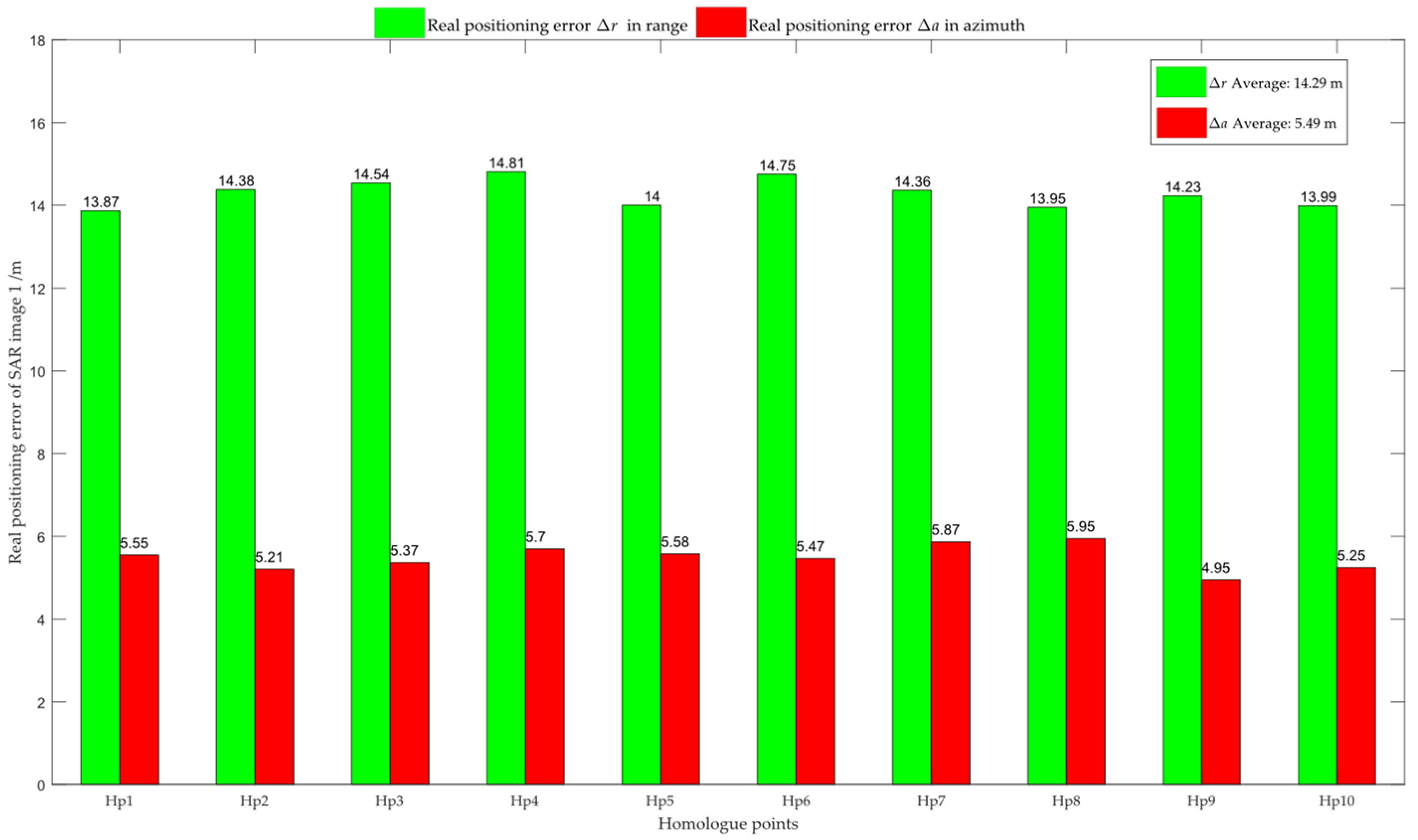
Figure 8.
The true systematic positioning error of the SAR image 2.

Figure 9.
The systematic positioning errors of the initial ground-range airborne SAR images, respectively, estimated by using 10 Hps.
Figure 9.
The systematic positioning errors of the initial ground-range airborne SAR images, respectively, estimated by using 10 Hps.
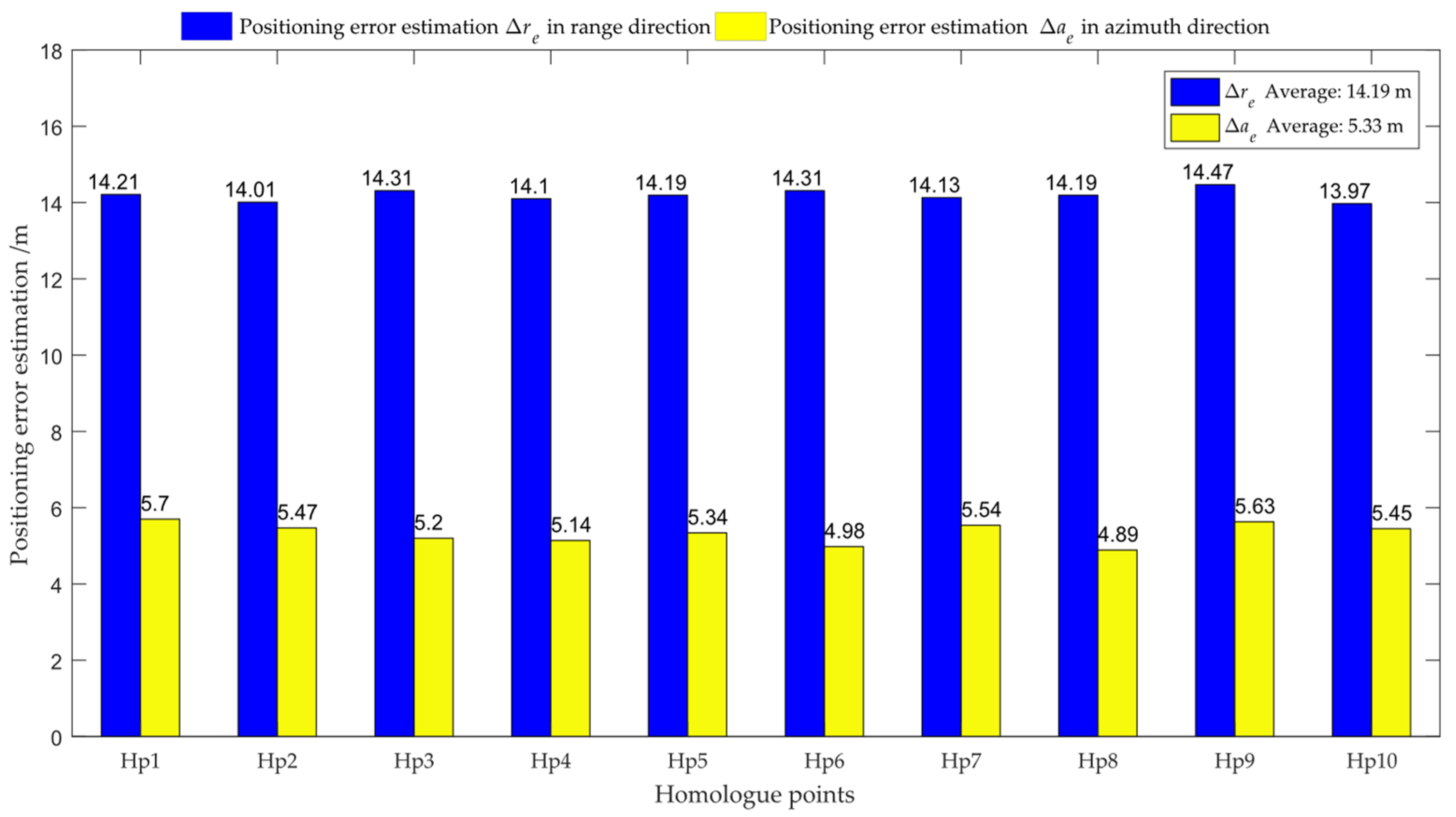
Figure 10.
The planar positioning error curves of six methods.
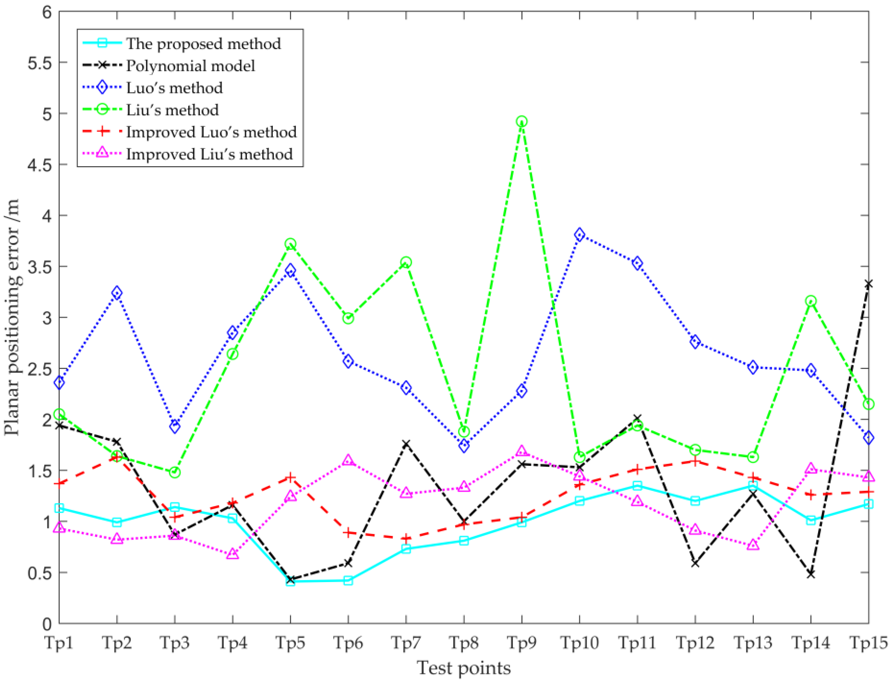
Figure 11.
Comparison of calibration effect. (a–d) Calibration effects of classical RD model, improved Luo’s method, improved Liu’s method, and suggested method on SAR image 1.
Figure 11.
Comparison of calibration effect. (a–d) Calibration effects of classical RD model, improved Luo’s method, improved Liu’s method, and suggested method on SAR image 1.

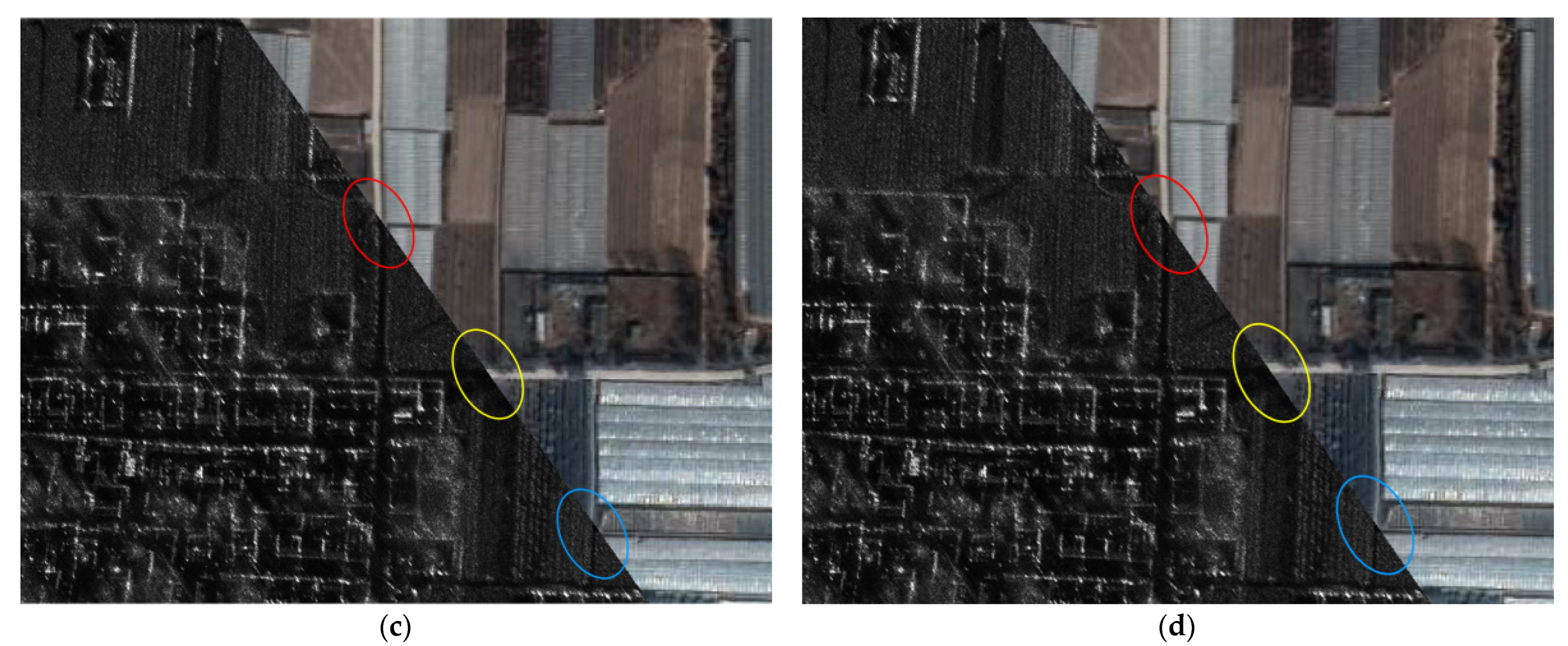
Figure 12.
Partial magnification of Hp1. (a) Magnification of Hp1 in SAR image 1; (b) Magnification of Hp1 in SAR image 2.
Figure 12.
Partial magnification of Hp1. (a) Magnification of Hp1 in SAR image 1; (b) Magnification of Hp1 in SAR image 2.
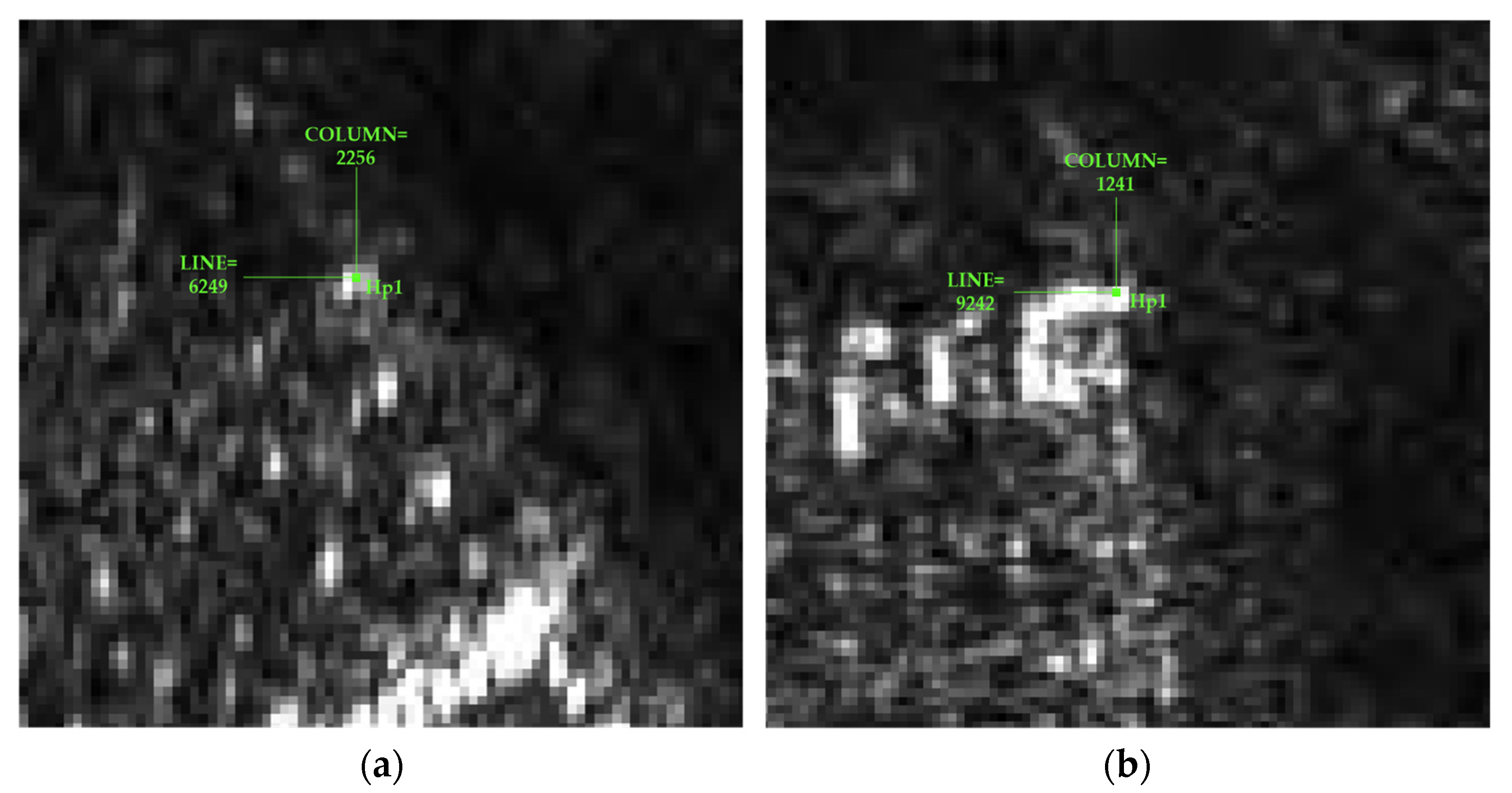
Figure 13.
Estimation curves of the positioning errors of the airborne SAR imagery by the suggested method when the aircraft exhibits inconsistent position measurement errors on two disparate courses. (a,b) The aircraft possesses position measurement error solely in the range direction; (c,d) the aircraft possesses position measurement error solely in the azimuth direction; (e,f) the aircraft has position measurement errors both in the range direction and the azimuth direction.


Table 1.
The system parameters of the airborne radar.
| Parameters | Value |
|---|---|
| Carrier frequency | 17 GHz |
| Bandwidth | 80 MHz |
| Platform height | 4 km |
| Platform velocity | 150 m/s |
| Slant-range of scene center | 10 km |
| Squint angle | 0° |
| Range sampling interval | 1.773 m |
| Azimuth sampling interval | 1.250 m |
Table 2.
The starting position of the radar to imaging and the real position of Hpi (i = 1, 2, 3, 4).
Table 2.
The starting position of the radar to imaging and the real position of Hpi (i = 1, 2, 3, 4).
| Type | Longitude/(°) | Latitude/(°) | Altitude/m |
|---|---|---|---|
| Starting position 1 | −90 | 0 | 4000.00 |
| Starting position 2 | −89.9543176 | 0.1189882 | 4000.00 |
| Hp1 | −89.9446175 | 0.0185621 | 3.31 |
| Hp2 | −89.9446175 | 0.0547369 | 5.87 |
| Hp3 | −89.8907187 | 0.0547368 | 14.49 |
| Hp4 | −89.8907187 | 0.0185621 | 11.93 |
Table 3.
The system parameter configurations for the two imaging sessions of the airborne radar.
| Parameters | First Imaging | Second Imaging |
|---|---|---|
| Frequency band | Ku | Ku |
| Imaging resolution (m × m) | 0.2 × 0.2 | 0.2 × 0.2 |
| Platform height (m) | 4266 | 4260 |
| Platform velocity (m/s) | 149.0450 | 173.2956 |
| Heading angle (°) | 143.89 | 171.78 |
| Longitude of imaging center (°) | 110.0676 | 110.0611 |
| Latitude of imaging center (°) | 34.7892 | 34.7937 |
| Range sampling interval (m) | 0.1259 | 0.1259 |
| Azimuth sampling interval (m) | 0.1380 | 0.0899 |
Table 4.
Airborne SAR target planar positioning error comparison with existing method (m).
| Point Number | Polynomial Model | Luo’s Method | Liu’s Method | Improved Luo’s Method | Improved Liu’s Method | The Proposed Method |
|---|---|---|---|---|---|---|
| Tp1 | 1.94 | 2.36 | 2.05 | 1.37 | 0.93 | 1.13 |
| Tp2 | 1.78 | 3.24 | 1.64 | 1.63 | 0.82 | 0.99 |
| Tp3 | 0.87 | 1.93 | 1.48 | 1.04 | 0.86 | 1.14 |
| Tp4 | 1.16 | 2.85 | 2.64 | 1.18 | 0.67 | 1.03 |
| Tp5 | 0.43 | 3.46 | 3.72 | 1.43 | 1.24 | 0.41 |
| Tp6 | 0.59 | 2.57 | 2.99 | 0.89 | 1.59 | 0.42 |
| Tp7 | 1.76 | 2.31 | 3.54 | 0.83 | 1.27 | 0.73 |
| Tp8 | 0.99 | 1.74 | 1.88 | 0.97 | 1.33 | 0.81 |
| Tp9 | 1.56 | 2.28 | 4.92 | 1.04 | 1.68 | 0.99 |
| Tp10 | 1.53 | 3.81 | 1.63 | 1.36 | 1.44 | 1.20 |
| Tp11 | 2.01 | 3.53 | 1.94 | 1.51 | 1.19 | 1.35 |
| Tp12 | 0.59 | 2.76 | 1.70 | 1.59 | 0.91 | 1.20 |
| Tp13 | 1.27 | 2.51 | 1.63 | 1.43 | 0.76 | 1.35 |
| Tp14 | 0.48 | 2.48 | 3.16 | 1.26 | 1.51 | 1.01 |
| Tp15 | 3.33 | 1.82 | 2.15 | 1.29 | 1.43 | 1.17 |
Table 5.
Planar positioning precision comparison among the six methods (m).
| Category | Polynomial Model | Luo’s Method | Liu’s Method | Improved Luo’s Method | Improved Liu’s Method | The Proposed Method |
|---|---|---|---|---|---|---|
| MAE | 1.35 | 2.64 | 2.47 | 1.25 | 1.17 | 0.99 |
| RMSE | 1.54 | 2.71 | 2.65 | 1.27 | 1.21 | 1.03 |
Table 6.
The influence of the pixel position acquisition errors of the Hp on the estimated positioning error of the SAR imagery (m).
Table 6.
The influence of the pixel position acquisition errors of the Hp on the estimated positioning error of the SAR imagery (m).
| Absolute Difference | Δi1 | Δj1 | Δi2 | Δj2 |
|---|---|---|---|---|
| |Δre2−Δre1| | 0.2252Δi1 | 0.3471Δj1 | 0.3511Δi2 | 0.2260Δj2 |
| |Δae2−Δae1| | 0.2478Δi1 | 0.0477Δj1 | 0.2478Δi2 | 0.0588Δj2 |
Disclaimer/Publisher’s Note: The statements, opinions and data contained in all publications are solely those of the individual author(s) and contributor(s) and not of MDPI and/or the editor(s). MDPI and/or the editor(s) disclaim responsibility for any injury to people or property resulting from any ideas, methods, instructions or products referred to in the content. |
© 2023 by the authors. Licensee MDPI, Basel, Switzerland. This article is an open access article distributed under the terms and conditions of the Creative Commons Attribution (CC BY) license (https://creativecommons.org/licenses/by/4.0/).
Share and Cite
MDPI and ACS Style
Zhang, B.; Yu, A.; Chen, X.; Tang, F.; Zhang, Y. An Image Planar Positioning Method Base on Fusion of Dual-View Airborne SAR Data. Remote Sens. 2023, 15, 2499. https://doi.org/10.3390/rs15102499
AMA Style
Zhang B, Yu A, Chen X, Tang F, Zhang Y. An Image Planar Positioning Method Base on Fusion of Dual-View Airborne SAR Data. Remote Sensing. 2023; 15(10):2499. https://doi.org/10.3390/rs15102499
Chicago/Turabian StyleZhang, Ben, Anxi Yu, Xing Chen, Feixiang Tang, and Yongsheng Zhang. 2023. "An Image Planar Positioning Method Base on Fusion of Dual-View Airborne SAR Data" Remote Sensing 15, no. 10: 2499. https://doi.org/10.3390/rs15102499
Note that from the first issue of 2016, this journal uses article numbers instead of page numbers. See further details here.