Article

Pyroclastic Flow Deposits and InSAR: Analysis of Long-Term Subsidence at Augustine Volcano, Alaska

1
Geophysical Institute, University of Alaska Fairbanks, Fairbanks, AK 99775, USA
2
Alaska Satellite Facility, Fairbanks, AK 99775, USA
3
State Key Laboratory of Earthquake Dynamics, Institute of Geology, China Earthquake Administration, Beijing 100029, China
4
Alaska Volcano Observatory, Fairbanks, AK 99775, USA
*
Author to whom correspondence should be addressed.
Remote Sens. 2017, 9(1), 4; https://doi.org/10.3390/rs9010004
Submission received: 23 September 2016 / Revised: 4 December 2016 / Accepted: 14 December 2016 / Published: 24 December 2016

Abstract

:
Deformation of pyroclastic flow deposits begins almost immediately after emplacement, and continues thereafter for months or years. This study analyzes the extent, volume, thickness, and variability in pyroclastic flow deposits (PFDs) on Augustine Volcano from measuring their deformation rates with interferometric synthetic aperture radar (InSAR). To conduct this analysis, we obtained 48 SAR images of Augustine Volcano acquired between 1992 and 2010, spanning its most recent eruption in 2006. The data were processed using d-InSAR time-series analysis to measure the thickness of the Augustine PFDs, as well as their surface deformation behavior. Because much of the 2006 PFDs overlie those from the previous eruption in 1986, geophysical models were derived to decompose deformation contributions from the 1986 deposits underlying the measured 2006 deposits. To accomplish this, we introduce an inversion approach to estimate geophysical parameters for both 1986 and 2006 PFDs. Our analyses estimate the expanded volume of pyroclastic flow material deposited during the 2006 eruption to be 3.3 × 10⁷ m3 ± 0.11 × 10⁷ m3, and that PFDs in the northeastern part of Augustine Island reached a maximum thickness of ~31 m with a mean of ~5 m. Similarly, we estimate the expanded volume of PFDs from the 1986 eruption at 4.6 × 10⁷ m3 ± 0.62 × 10⁷ m3, with a maximum thickness of ~31 m, and a mean of ~7 m.

Graphical Abstract

1. Introduction

Interferometric synthetic aperture radar (InSAR) is well established as a means for identifying terrain deformation associated with volcanic activity [1,2,3,4,5]. InSAR processing can be used to measure changes in the surface deformation with centimeter to sub-centimeter accuracy at regional scales as terrains inflate and deflate with subsurface magma intrusion and extrusion [6,7], and also at local scales as post-eruptive materials subside through compaction, degassing, and other mechanisms [8,9].
All eruptive materials are subject to localized deformation, with each material having its own particular characteristics Common examples of these characteristics are observed in lavas and pyroclastic flow deposits. Lavas are flows of magma that have erupted at the Earth’s surface effusive volcanic activity [10]. Pyroclastic flows are produced by more violent explosive activity or gravitational dome collapse [11]. They can be described, generally, as hot, gravity controlled, rapidly moving flows of high particle-concentration ash and gas, and, in some instances, may be partly fluidized [10]. They are the high-solids end member of the more broadly defined pyroclastic density currents, which include a mixture of both pyroclastic flows and a more dilute, highly turbulent end member called a pyroclastic surge [12].
Most eruptive products, especially lava, pyroclastic flow deposits, and pyroclastic surge deposits, are not static once emplaced. Vertical displacement continues within each [13,14,15], albeit at different rates based on individual rheology and susceptibility to erosion and compaction. Vertical displacement of this nature can be accurately measured with InSAR, which in turn provides clues to the materials’ thermo-mechanical. This paper is concerned with pyroclastic flow deposits (PFDs). But pyroclastic flow processes are highly complex; consequently, no single description of their deposits satisfies all conditions. As Williams and McBirney observed, “many classifications of pyroclastic flows have been proposed, but none is without its deficiencies” [11], and Schmincke added, “a well-documented general discussion of the many terms and genetic concepts for the origin of pyroclastic flows and their deposits covering the last 100 years would require a long chapter on its own” [16]. Over decades of research, pyroclastic flows have been variously described as nuée ardentes, glowing avalanches, incandescent tuff flows, ash flows, sand flows, and block-and-ash flows, and related deposits as PFDs, ignimbrites, ash-flow tuffs, and welded tuffs, to name a few. Regardless of nomenclature, however, the underlying commonality is that each represents an unconsolidated deposit laid down at high temperature [11].
In this paper, PFDs describe deposits of unconsolidated rock and ash from the high-solids end member of a pyroclastic density current, regardless of its origin, mechanism of transport, or particle concentration [12]. More specifically, we examine the thickness and long-term deformation of PFDs at Augustine Volcano, Alaska, and present methods that can be used to determine those parameters from InSAR measurements acquired between 1992 and 2010, and to model the thickness of the historical 1986 PFD that underlies the observable 2006 deposits.
Augustine Volcano (Figure 1) was selected for this work because its eruption history is both frequent and relatively recent. Moreover, its last two eruptions, in 1986 and 2006, resulted in significant PFDs on its north flank, as shown in Figure 2a,b. This layered deposition requires observation of deformation behavior in two overlying generations of PFDs. Although this is a condition commonly found at active volcanoes, it complicates measurements of surface deformation, because any such measurement will contain the combined effect of a number of superimposed PFDs. Analyzing one individual deposit, therefore, is not possible from direct measurements alone. To solve this issue, we use a combination of long-term InSAR observations and basic geophysical models to decompose contributions from several generations of overlying PFDs and derive specific geophysical information. At Augustine Volcano, SAR data suitable for interferometry are available from June 1992 to October 2005, from March 2006 to April 2007, and from July 2007 to October 2010, spanning its most recent eruption in 2006. By using these data in combination with geophysical models, we were able to project deformation rates back to pre-SAR periods from 1986 to 1992 and estimate original thickness and long-term subsidence rates for PFDs related to Augustine Volcano’s two most recent eruptions in 1986 and 2006.
Consistent with previous observations of PFDs [19,20], we found that PFDs from the 2006 eruption rapidly subsided for an initial post-emplacement period, before slowing to a more persistent and linear long-term rate. For Augustine, we found that the initial post-emplacement period was about six months and the long-term subsidence rate was proportional to the deposits’ thickness, which allows for the assessment of deposit thickness from measured subsidence rates and vice versa.

2. Augustine Volcano

Augustine Volcano is located in Cook Inlet, Alaska, approximately 285 km southwest of Anchorage (Figure 1). It completely occupies its namesake Augustine Island, an 8 km × 11 km, uninhabited island of pyroclastic debris surrounding a central dome complex. It is the youngest and most active of five historically active volcanoes in the Cook Inlet area, which, besides Augustine, include Mt. Spurr, Redoubt Volcano, Iliamna Volcano [21], and most recently Fourpeaked Mountain, which experienced a minor eruption in 2006 [22,23].
Since its discovery by James Cook in 1778 [24], Augustine Volcano has had major eruptions in 1883, 1908, 1935, 1964, 1976, 1986, and 2006 [25]. Its 1883 eruption, the first to be contemporaneously documented, is also considered its most violent [26,27]. It began on 6 October 1883, when an edifice collapse extended the north coastline of the island by 2 km [28], and a resulting debris avalanche, which extended another 2.5 km into Cook Inlet [29], caused a tsunami in the range of 6 m to 9 m at the English Bay settlement, 85 km to the west [30,31], Figure 1 (English Bay was renamed Nanwalek on 12 July 2007 by the USGS Board of Geographic Names [32]; the name English Bay is used here for continuity with previous work). Contemporaneous accounts describe the English Bay tsunamis destroying fishing boats and inundating houses [31], and accompanying ash falls were sufficient to bury Aleut barabaras, the communal houses of the Aleuts and some Inuit bands of native Alaskans (from 1898 field notes of Spurr, J.A. quoted by Kienle et al. [33]).
Over the next 123 years, through 2006, Augustine erupted on least six occasions, with significant pyroclastic flows occurring in 1964, 1976, 1986, and 2006. Each of these eruptions were similar in nature and composition, beginning with an initial explosive phase (VEI ~3), followed by a period of decreasing intensity, and finally, an effusive, dome building phase [34,35,36]. Although Augustine has had four eruptions in the past 50 years, this paper examines the two most recent eruptions in 1986 and 2006. This was a practical limitation, because civilian Earth-Observing radar imaging satellites suitable for interferometry were not available before the launch of ERS-1 [37]. In any case, by the time SAR satellite data were available, much of Augustine’s pre-1986 eruptive products had been overlain by its subsequent eruption.

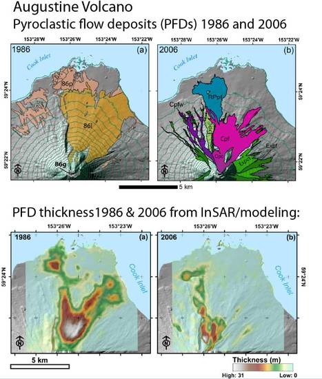
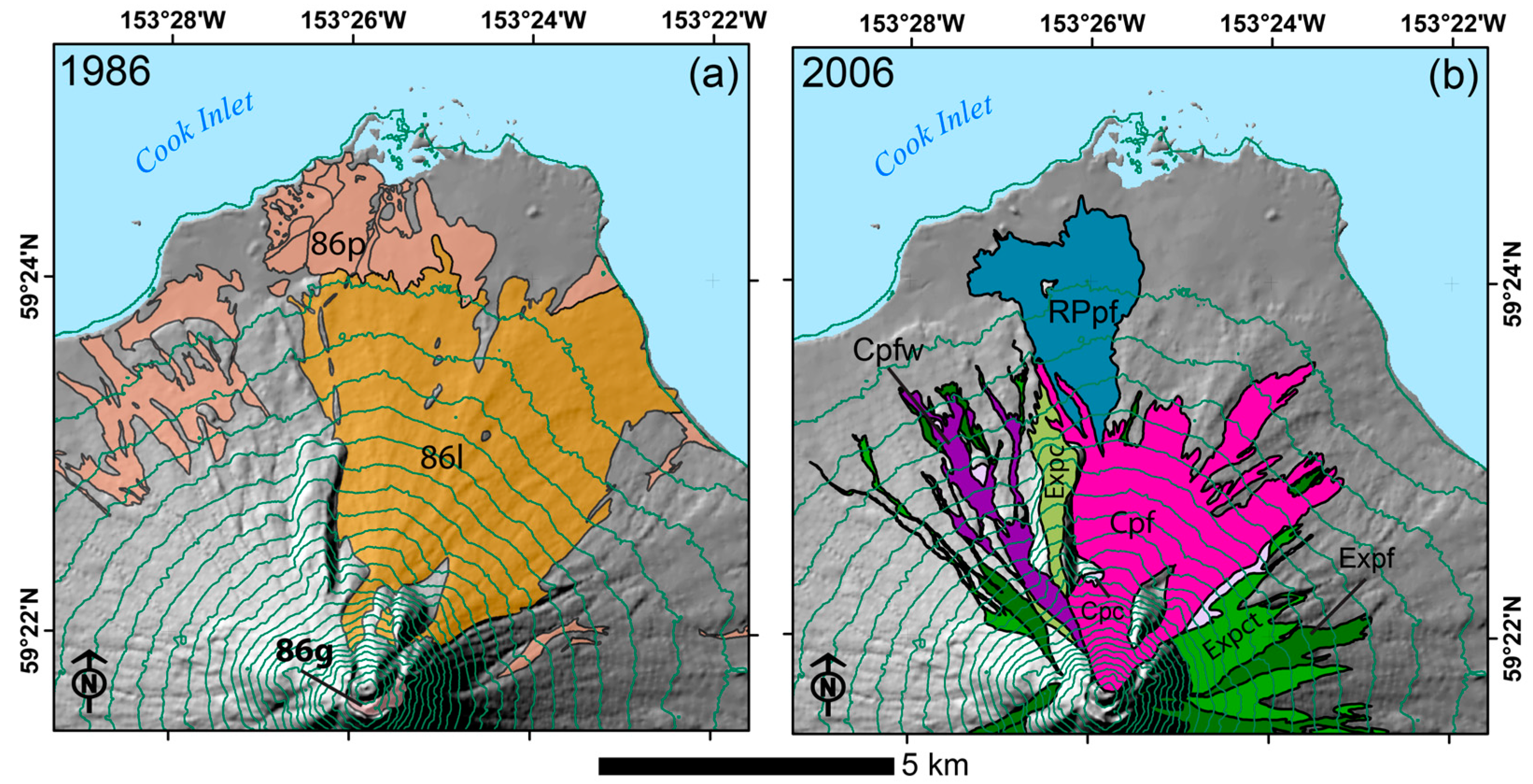
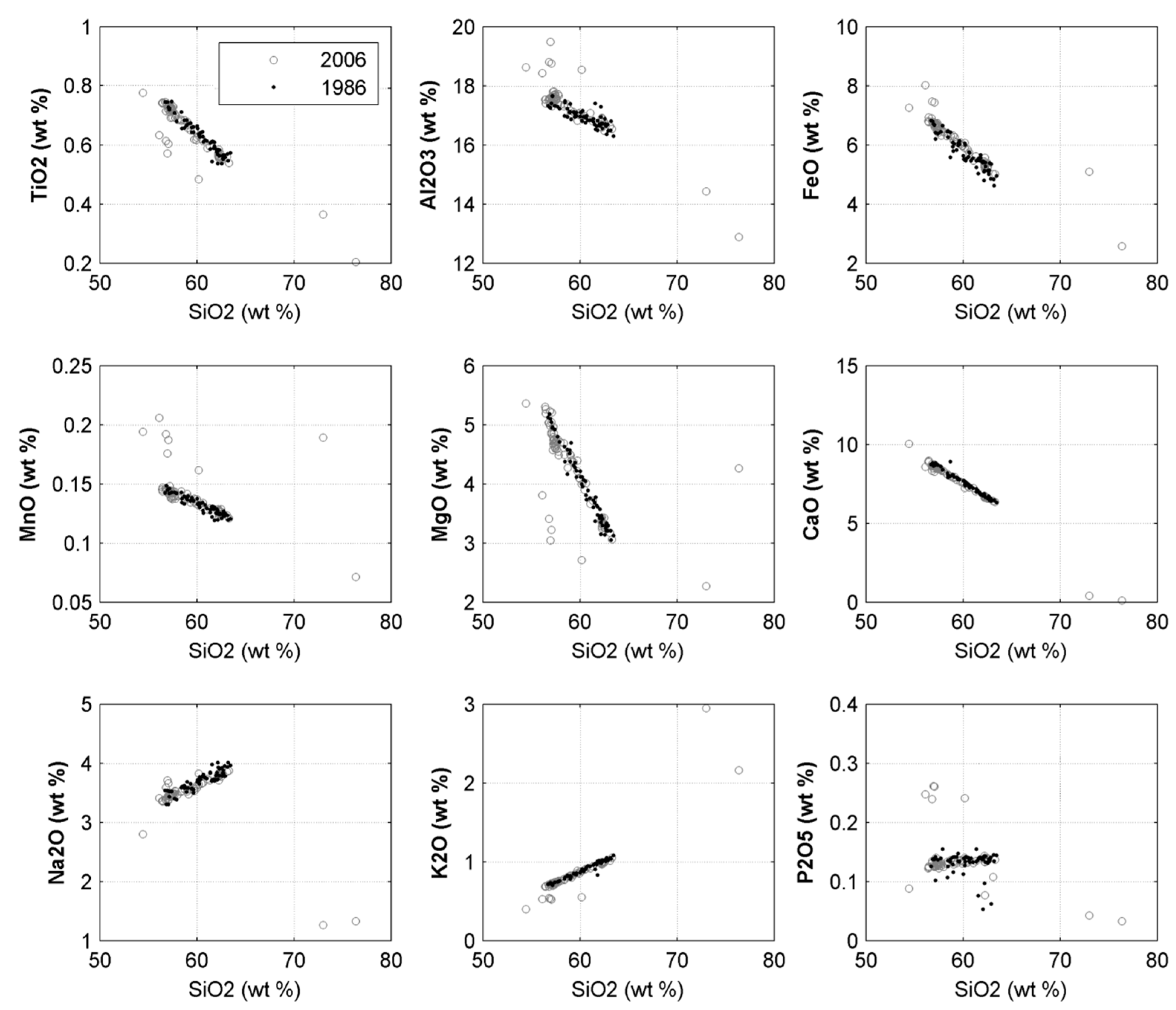
2.1. The 1986 Eruption and Its PFDs

The 1986 eruption began 27 March and continued with three main episodes, from 27 March–2 April; from 23–28 April; and 22 August–1 September [26]. A large andesitic dome resulting from the eruption engulfed a dome emplaced in 1976, which had, in turn, incorporated part of a 1935 dome and all of the 1883 dome [28]. In the first and most explosive episode of the eruption, a nearly continuous ash plume reached altitudes of 4.6 km above sea level (ASL), while explosions generated episodic ash clouds up to 12.2 km ASL. Hundreds of pyroclastic flows extended down the north and northeast flanks, with the largest of these reaching Cook Inlet, to the west and east of Burr Point, some 5 km from the summit vent [26]. Early in the eruption, these flows were rich in pumice. In latter stages, dome collapse events created more lithic pyroclastic flows of dome rock (porphyritic andesite), leaving a broad fan on the north flank, downslope from the 1986 dome [28] (Figure 2a). Pyroclastic flows continued during the late April and August episodes of the eruption, but these were greatly reduced in number and on a smaller scale. Lava was eventually produced from the summit vent, flowing down a gully on the north flank until formation of a dome in late August [26].

2.2. The 2006 Eruption and Its PFDs

At the conclusion of its 1986 eruption, Augustine was quiescent for nearly 20 years, until a 6-month period of pre-eruption seismicity began in the summer of 2005 [34]. On 11 January 2006, the volcano erupted in a 17-day series of explosions that would be the first of three distinct eruption phases. This first phase, termed the “Explosive Phase”, produced ash plumes up to 14 km ASL, along with lava flows and a number of pyroclastic flows on the north flank. These included the largest flow of the Explosive Phase, which, at 4.8 km in length, was designated by Coombs et al. [34] as the Rocky Point Pyroclastic Flow (see RPpf deposit in Figure 2b). On 28 January, the volcano’s Explosive Phase ended, and a 13-day period of essentially uninterrupted activity began. This was the “Continuous Phase”, so named to separate it from the discrete explosions of the previous Explosive Phase. The Continuous Phase was characterized by nearly constant, rapid effusion, numerous pyroclastic flows on the north flank [12], and episodic seismic activity. Especially during the early stage of this phase, pyroclastic flows were common, and their deposits would eventually cover an area of 4.9 km² and extend from the summit vent more than 3.8 km down the north flank.
The 2006 eruption concluded with a final, 13-day Effusive Phase from 3–16 March. This phase followed a 21-day hiatus in activity, and resulted in a larger summit dome, increased lava flows on the north flank, and significant block and ash flows. The eruption concluded on 16 March, when no further juvenile material was observed [34].
A comparison of eruption products from 2006 indicates broad compositional overlap with those from 1986. Silica variation diagrams of major element, whole rock compositions of 70 samples from the 2006 eruption [38], overlaid with 60 whole-rock samples from the 1986 eruption [39] are presented in Figure 3. These compositional similarities imply that the 1986 and the 2006 PFDs have similar thermo-mechanical properties, which will cause them to deform in a similar fashion as they cool.

3. Data Sets

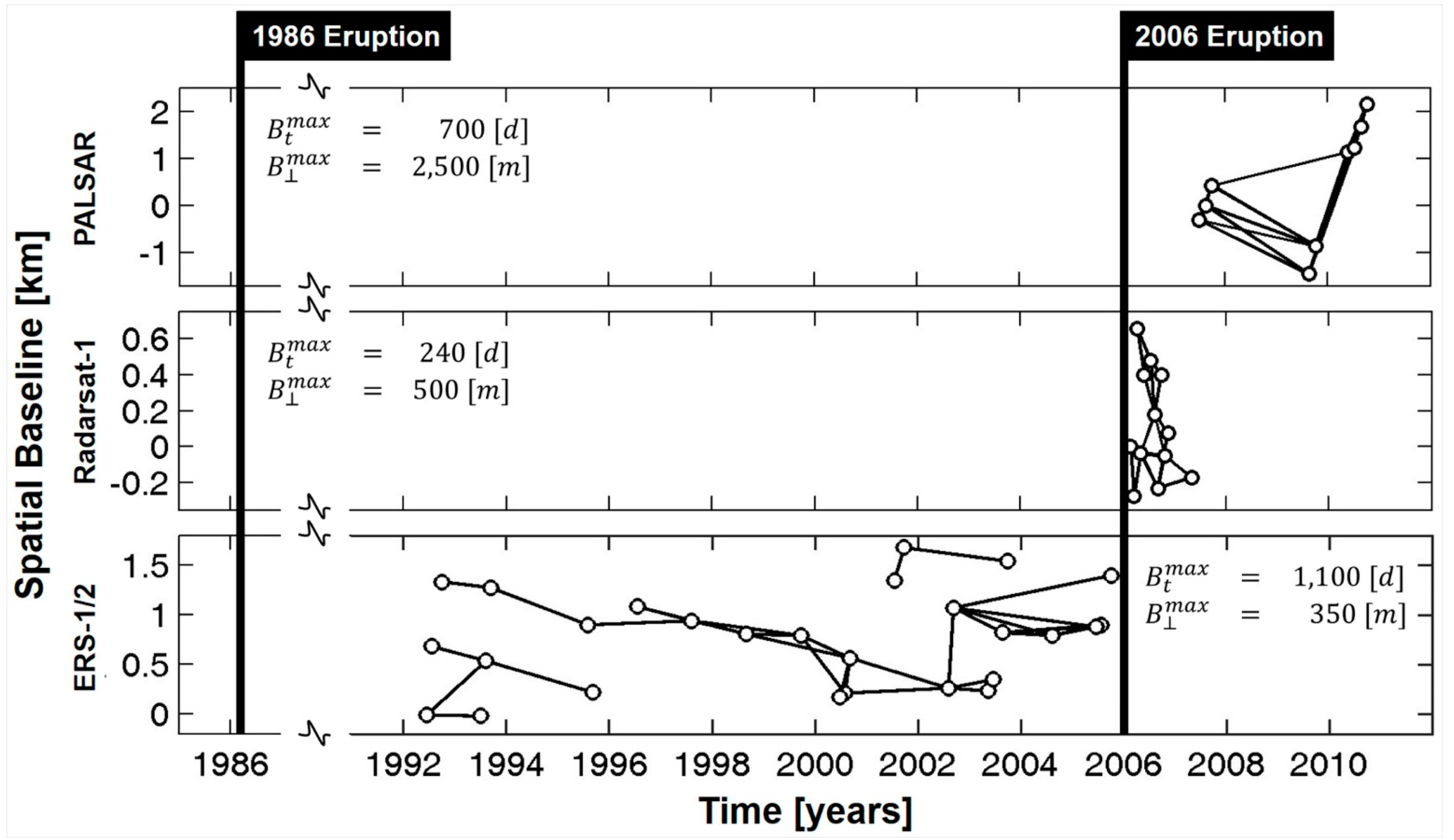
3.1. Available SAR Data

To study PFDs related to the 1986 and the 2006 eruption, the use of data from multiple SAR sensors is a practical necessity. No single SAR sensor was in service for the nearly 20-year period between the 1986 and 2006 eruptions, and no permanent spaceborne SAR system existed at the time of the 1986 eruption. The first European Remote Sensing (ERS) satellite, ERS-1, did not fly until 1991 [40], and both ERS-2 and Canada’s Radarsat-1 were launched in 1995 [41,42]. The Phased Array L-band Synthetic Aperture Radar (PALSAR) aboard Japan’s Advanced Land Observing Satellite (ALOS) was the most recent sensor used in this study. ALOS-PALSAR was launched on 24 January 2006, but was not operational until October 2006 [43], several months after the cessation of the 2006 eruptive activity.
To analyze the eruption deposits, we obtained a total of 48 SAR single look complex (SLC) images acquired between 21 June 1992 and 9 October 2010. The images were acquired across four platforms, in C-band and L-band wavelengths (λ). C-band data were obtained from Radarsat-1 (λ = 5.6 cm), ERS-1, and ERS-2 (λ = 5.66 cm); L-band data (λ = 23.62 cm) were acquired by ALOS-PALSAR. All SAR data used in this study together with their platform identifiers are listed in Table 1.

3.2. Ancillary Data Used in This Study

The reference digital elevation model (DEM), used for InSAR analysis was acquired during the Shuttle Radar Topography Mission (SRTM) in February, 2000 (tile No. SRTM1N59W154V2). SRTM was a cooperative project of the National Aeronautics and Space Administration (NASA), the National Imagery and Mapping Agency (now the National Geospatial Intelligence Agency, or NGA), and the German agency Deutches Zentrum für Luft und Raumfahrt (DLR) [44]. The SRTM elevation data were processed from original radar signals spaced at intervals of 1 arc-second (~30 meters), with additional, later processing employed to fill voids where initial processing did not meet mission specifications. The SRTM data meet absolute horizontal and vertical accuracies of 20 m (circular error at 90% confidence) and 16 m (linear error at 90% confidence). In North America, the relative vertical accuracy of the SRTM DEM was measured to be 7 m (linear error at 90% confidence) [45].

4. Data Processing Methods

Data processing was conducted in two steps. In the first step, SAR data from ERS-1/2, Radarsat-1, and ALOS-PALSAR sensors were separately processed to evaluate PFD subsidence between 1992 and 2010 (Section 4.1). Emphasis was placed on deformation occurring on Augustine’s north flank, where the great majority of PFDs were emplaced. In a second step, these subsidence data were used to derive geophysical information, such as deposit thickness and deformation behavior, for both the 1986 and 2006 PFDs. This latter process proved less straightforward, however, because data acquired after the 2006 eruption measures the combined deformation of superimposed multiple generations (1986 and 2006) of PFDs. We therefore devised an approach that decomposes contributions from 1986 and 2006 PFDs by combining subsidence data with geophysical models. In the following sub-sections, we will describe those models and the processing methods used in this two-step strategy. A geophysical interpretation of results is presented in Section 5. A summary of variables used in the following Equations (1)–(16) is presented as Appendix A.

4.1. Methods: Differential InSAR (d-InSAR) Time-Series Processing

Differential InSAR (d-InSAR) time-series analysis techniques use the phase measurements of a stack of N + 1 co-registered SAR images observed at image acquisition times [ t 0 , , t N ] , to extract accurate information about the (time-dependent) deformation of an observed surface. To this end, a set of M interferograms is first formed from the N + 1 images using InSAR processing, which calculates the phase difference ϕ i , j (typically referred to as the interferometric phase) between pairs of SAR images according to
ϕ i , j = φ i φ j
where ϕ i , j is the interferometric phase measurement calculated from SAR images i and j ( i ,   j ( N + 1 ) and i < j ). As shown in Equation (2), the phase values in Equation (1) contain information about the topography h of the observed surface encoded in phase component ( ϕ i , j , t o p o ) as well as the surface deformation Δ d i , j = ( d j d i ) that occurred between the image acquisition times t i and t j   ( ϕ i , j , d e f o ) . In addition to these desired parameters, however, ϕ i , j is furthermore affected by differences in the atmospheric stratification at times t i and t j ( ϕ i , j , a t m s ), variations in the distribution of atmospheric water vapor ( ϕ i , j , a t m t ), errors in satellite orbits ( ϕ i , j , o r b i t ), and noise ( ϕ i , j , n o i s e ), such that ϕ i , j can be written as
ϕ i , j = ϕ i , j , d e f o + ϕ i , j , t o p o + ϕ i , j , a t m s + ϕ i , j , a t m t + ϕ i , j , o r b i t + ϕ i , j , n o i s e
The sensitivity of the phase values in Equation (2) to the target parameters h (surface topography), and Δ d i , j , (surface deformation), is given by:
ϕ i , j , t o p o = 4 π λ B i , j , r · s i n ( θ ) h
and
ϕ i , j , d e f o = 4 π λ ( d j d i )
where B i , j , is the perpendicular baseline between SAR acquisitions i and j , r is the sensor-to-target range, θ is the look angle of the system, and λ is the wavelength of the transmitted signal.
In this study, we use d-InSAR time-series analysis techniques to extract information about the time-dependent surface deformation d n = [ d 0 , , d N ] of PDFs emplaced on Augustine’s northern flank during both the 1986 and 2006 eruptions from the measurements in Equation (2). From SAR data acquired after the 2006 eruption, we extract information about the thickness h P F D , 06 of PFD deposits emplaced by this eruption. Here, we interpret the SAR-observed post-eruptive surface topography h in Equation (3) as the combination of a pre-eruptive DEM h p e and the thickness h P F D , 06 of 2006 deposits, i.e., h = h p e + h P F D , 06 .
To extract d n from the observed phase measurements ϕ i , j , we first mitigate phase signals related to the pre-eruptive DEM h p e from Equation (2) by subtracting topographic phase values obtained from the 1 arc-second resolution SRTM digital elevation model (d-InSAR processing). We subsequently model and subtract stratified atmospheric phase signals ( ϕ i , j , a t m s ) from Equation (2) using the Weather Research and Forecasting (WRF) model and following the approach described in Gong et al., [46,47]. This separate step is required as stratified atmospheric signals are significant at Augustine and can often not be removed using spatial or temporal filters. Finally, we mitigate orbital errors ( ϕ i , j , o r b i t ) by referencing all phase values to a stable region near the PFDs of interest, and apply an adaptive phase filter [48] to minimize ϕ i , j , n o i s e .
After individually unwrapping the filtered differential interferograms using a minimum-cost-flow unwrapping algorithm [49], the unwrapped differential interferometric phase resulting from these processing steps can be written as
Δ ϕ i , j 4 π λ ( d j d i ) + 4 π λ B i , j , r · s i n ( θ ) Δ h + ϕ i , j , a t m t + ϕ i , j , n o i s e
where Δ h is a residual topography signal that may be due to errors in h p e or due to real changes of topography since the acquisition of h p e .
A final set of two processing steps remain to arrive at estimates for the deformation time series d n . First, we apply the small baseline subset (SBAS) algorithm of Berardino et al., [50] to the data in Equation (5). In SBAS, interferograms are formed from the subset of all possible SAR image pairs, whose temporal ( B t ) and spatial baselines ( B ) are within pre-defined thresholds. By limiting B t and B , SBAS addresses the difficult problem of coherence loss, or decorrelation, in interferometric data [50,51] and therefore reduces the impact of ϕ i , j , n o i s e on Δ ϕ i , j . Moreover, processing interferograms within the SBAS framework reduces atmospheric effects ϕ i , j , a t m t in Equation (5), by applying spatial and temporal filters to the InSAR time-series data [52]. By inverting the differential phase measurements Δ ϕ i , j in Equation (5), the algorithm results in the reconstructed phase history Δ φ n at the N + 1 image acquisition times [ t 0 , , t N ]
Δ φ n = 4 π λ B n , r · s i n ( θ ) Δ h + 4 π λ d n
For reasons of simplicity, Equation (6) assumes that atmosphere and noise influences were sufficiently reduced by the filtering steps in our SBAS workflow so that they can be considered negligible and dropped from the equation. This approximation is made to keep the description of our processing approach mathematically short. Note that in reality, noise and atmospheric effects are only reduced but not eliminated during SBAS processing.
In addition to Δ φ n , we also derive an estimate of its uncertainty, σ Δ φ n , through our SBAS implementation. This uncertainty estimate is derived for each pixel and epoch using a jackknifing approach: For our data set of M interferograms formed from N + 1 SAR acquisitions, we calculate N + 1 solutions for Δ φ n by recursively dropping the n th acquisition date from our list of observations. The standard deviation of the N + 1 derived solutions for Δ φ n forms the uncertainty estimate, σ Δ φ n . Note, that our approach for uncertainty estimation does not consider spatial correlations between pixels that might be introduced by residual atmospheric signals as well as by the application of spatial filters in our workflow. These correlations are currently ignored but could be included in the future.
In Equation (6), the variable d n is the cumulative line-of-sight displacement at time t n , and B n , is the perpendicular baseline between the SAR image acquisition at time t n and the reference-image acquisition at time t 0 .
For interferometric data acquired before Augustine’s 2006 eruption, we assume that Δ h is small such that its impact on Δ φ n can be ignored and the deformation time series d n can be directly extracted from Equation (6). To validate this assumption, we have analyzed short term ERS-1/2 interferograms with spatial baselines typical for our ERS data stack (up to ~250 m) over non-deforming areas of the Augustine edifice and found residual phase signals with a standard-deviation of about 0.8 rad. The spatial pattern of these residual signals suggests atmospheric delay effects as the main source. Hence, we decided to not correct for topographic effects but rather model their error influence according to Equation (3) and consider them in the statistical model for the estimation of d n along with phase noise due to the data’s coherence properties. Here, we use σ h p e = 7 m to model the accuracy of the SRTM DEM, which is its relative height error estimated by Rodriguez et al., [45] for the North American continent.
For data acquired after 2006, we assume that the residual topography signal is an expression of the deposit thickness h P F D , 06 and apply the approach by Fattahi and Amelung [53] to jointly estimate the unknown parameters of the deformation time series d n from the unknown PFD thickness h P F D , 06 . Errors in the pre-eruption DEM ( σ h p e ) were included in the error model for h P F D , 06 . Interested readers are referred to Berardino et al., [50] and Fattahi and Amelung [53] for more technical details on the applied SBAS and DEM error estimation approaches.
Using this approach, we derive line-of-sight deformation time-series information separately from the ERS1/2, Radarsat-1, and ALOS PALSAR data, resulting in the deformation time series d n 92 05 , d n 06 07 , and d n 07 10 , respectively. To reduce the influence of any potential larger-scale, magma-related deformation of Augustine’s edifice on the deformation estimates, we chose three reference points on the north flank that were unaffected by PFDs (Figure 2b). To facilitate subsequent joint processing of these time-series data (Section 4.2), we assume that PFD deformation is dominated by vertical subsidence motion [15,54], and project all deformation measurements together with their error properties into a joint vertical reference frame, resulting in the subsidence estimates s n 92 05 , s n 06 07 , and s n 07 10 , with their respective uncertainty measures σ s n . The assumption of vertical motion is consistent with other work on Augustine’s PFDs [54].
From the ALOS PALSAR data, acquired after the 2006 eruption, we furthermore derive an estimate for the thickness h P F D , 06 of the 2006 PFDs. In Section 4.2, we introduce an inversion approach that is used to estimate physical parameters for the 1986 and the 2006 PFD deposits from these measurements.
Note, that a similar approach for the joint estimation of the thickness and subsidence of volcanic deposits was also applied by Ebmeier et al., [55]. There, InSAR data was used to estimate thickness and deformation of lava deposits on Santiaguito Volcano, Guatemala. In contrast to their approach, which measured the cumulative deformation of material deposited during an extended extrusive event, we are tracking deposit deformation across two eruptive cycles that resulted in a superposition of multiple generations of PFDs. Hence, in our case, further processing is needed to decompose contributions from 1986 and 2006 PFDs and extract geophysical information for the individual PFD generations.

4.2. Methods: Geophysical Model of PFD Parameter Estimation

The overall goal of this study is to extract geophysical information about the 1986 and 2006 PFDs from the InSAR-derived subsidence estimates, s n 92 05 , s n 06 07 , and s n 07 10 . This effort is complicated (at Augustine and at most other active volcanoes) by younger 2006 deposits that are superimposed onto earlier 1986 material (Figure 2a,b). Consequently, surface deformation data acquired after the 2006 eruption includes the effect of subsiding new material as well as residual contraction of the underlying 1986 deposits.

4.2.1. Geophysical Considerations and Model Assumptions

To discriminate between contributions from individual deposits in our deformation measurements, we employ a simplified model that assumes the contraction behavior of 1986 and 2006 deposits can be modeled using the same physical principles and same material parameters. We base this assumption on the geochemical similarity of eruption products from both 1986 and 2006, as described in Figure 3 and Section 2.2.
We further consider four possible geophysical sources that may give rise to the observed deformation at Augustine-type PFDs: (1) surface deflation due to loss of volatiles; (2) surface inflation or deflation caused by volume changes in the magma reservoir; (3) poroelastic deformation caused by loading; and (4) thermoelastic surface deformation due to cooling. Of these four mechanisms, only two—deformation from loading, and thermoelastic cooling—were considered significant. Whereas loss of volatiles contributes to deformation, observations of deflating PFDs acquired at Mount St. Helens in 1980 indicate that most deflation occurs immediately—within hours or days—after emplacement [19]. We assume that gas deflation at Augustine was similar in timing and extent, and, therefore, deformation from deflation was complete before satellite observations were made after the 1986 and 2006 eruptions.
Centimeter-scale ground deformation attributed to magma movement, particularly in periods immediately preceding or following an eruption, is well established in a number of previous studies [1,4,56,57,58,59]. At Augustine, however, magma source-related deformation has been subtle and at or below the detection level of geodetic systems for most of its recent history. Both an InSAR analysis of Augustine from 1992 to 1999 [60] and a study based on optical, electronic, and GPS surveying techniques [61] found no evidence of magma-related deformation. While subtle magma-related deformation signals were found for the time period 1988–2000 from both reprocessed GPS data and InSAR data [52], the magnitude of the signal was near the detection level of both techniques.
An exception to this general behavior was a deformation episode that started immediately before and lasted through the initial phases of the 2006 eruption [36]. While this deformation was significant, it occurred at a time not covered by our SAR data and had almost entirely ceased at the time of our first SAR acquisition after the 2006 eruption. We therefore ignore magma source-related deformation in our geophysical model. Note, that our choice of a reference point nearby the deforming PFDs further mitigates magma-induced surface deformation signals that may have existed.
The remaining sources of deformation considered in our model are compaction-related poroelastic deformation and thermal contraction. We are able to pretermit the effects of compaction as a cause of persistent subsidence, because such effects last as little as hours or days after emplacement [19,54], while thermoelastic contraction persists for years [20]. Our consideration of poroelastic compaction is therefore limited to the period immediately after emplacement (Equation (8)). Finally, we assume that the subsidence time series s n 92 05 , s n 06 07 , and s n 07 10 are sufficiently linear such that they can be approximated by linear functions of the form:
s n = Δ s · t n
where Δ s is the linear subsidence rate in cm·year−1. This linearity assumption has major advantages when formulating our geophysical model as it significantly reduces the number of unknowns that need estimation. As some researchers (e.g., [54]) have proposed exponential models in the past, we provide a more detailed justification for this linearity assumption in Section 5.1 where we show that the model in Equation (7) is supported by the data.
With these prerequisites in place, we were able to construct a forward model that relates each of the subsidence rate estimates, Δ s 92 05 , Δ s 06 07 , and Δ s 07 10 to physical parameters of the 1986 and 2006 PFDs.

4.2.2. Model Formulation

Because poroelastic deformation of the 1986 PFDs had likely ceased before the start of our observation time series, we are able to limit our estimate of the initial subsidence rate, Δ s 92 05 , to a function of thermoelastic contraction and thickness:
Δ s 92 05 = γ ¯ t h · h P F D , 86 ; [ cm   t 1 ]
where h P F D , 86 [m] is the (unknown) thickness of the 1986 deposits and γ ¯ t h = α L · k ¯ [cm t−1 m−1] is the unknown average thermoelastic contraction parameter of Augustine-type PFDs that is proportional to the material’s thermal contraction coefficient α L and its time-averaged cooling rate k ¯ .
The second subsidence rate, Δ s 06 07 , describes the deformation behavior immediately after the emplacement of the 2006 PFDs. Because it is affected by poroelastic and thermoelastic deformation of 2006 materials as well as thermoelastic deformation of underlying 1986 materials, it is modeled as:
   Δ s 06 07 = ( γ ¯ p e + γ ¯ t h ) · h P F D , 06 + Δ s 92 05 or ( Δ s 06 07 Δ s 92 05 ) = ( γ ¯ p e + γ ¯ t h ) · h P F D , 06
where γ ¯ p e (cm·year−1·m−1) is an average poroelastic contraction parameter and γ ¯ t h is the average thermoelastic contraction parameter from Equation (8).
For the third subsidence rate, Δ s 07 10 , which starts more than one year after emplacement of the 2006 PFDs, we assume that poroelastic contraction has ceased, such that:
( Δ s 07 10 Δ s 92 05 ) = γ ¯ t h · h P F D , 06
Note that the average thermoelastic contraction parameter γ ¯ t h is assumed to be identical for the 1986 and the 2006 PFDs. This assumption is based on their compositional similarity (Figure 3).
To solve this system of equations (Equations (8)–(10)), we apply two consecutive, linear least-squares inversions. In the first, we derive estimates for the parameters γ ¯ t h and γ ¯ p e from Equations (9) and (10) using a least-squares parameter estimation in the Gauss-Markov model [62]. To that end, Equations (8) and (9) are rearranged to take the form:
b + ε ^ = A · x ^
In Equation (11), b is a ( 2 · R · C ) × 1 column vector of observations, with R and C being the number of rows and columns of the InSAR data matrix; ε ^ is the ( 2 · R · C ) × 1 column vector of estimated residuals; x ^ is the 2 × 1 column vector of unknowns; and A is the ( 2 · R · C ) × 2 design matrix containing the partial derivatives of the forward model in Equations (8) and (9) with respect to the unknowns x ^ ( E q . ( 9 ) / γ ¯ t h = E q . ( 10 ) / γ ¯ t h = h P F D , 06 ; E q . ( 9 ) / γ ¯ p e = h P F D , 06 ; E q . ( 10 ) / γ ¯ p e = 0 ).
We model errors in observations using covariance matrix Σ b b from which we derive a matrix of weights P b b for the observations b in the parameter inversion according to:
P b b = ( Σ b b ) 1
The covariance matrix Σ b b is a diagonal matrix containing the variances σ Δ s 2 of the subsidence rate estimates, Δ s . The values σ Δ s 2 are derived by propagating the uncertainties σ s n through Equation (7). Following the Gauss-Markov theorem, the optimal solution for the problem in Equation (11) is found by minimizing the object function δ:
δ = ε ^ T P b b ε ^ m i n
Solving this minimization problem yields the estimated unknowns x ^ = [ γ ¯ t h γ ¯ p e ] T with their covariance properties Σ x ^ x ^ according to:
x ^ = ( A T P b b A ) 1 A T P b b b Σ x ^ x ^ = ( A T P b b A ) 1
resulting in estimates for γ ¯ t h and γ ¯ p e .
Once these parameters were derived, the estimate for γ ¯ t h together with its accuracy properties are used in a second inversion of Equation (7) to derive estimates for the thickness h ^ P F D , 86 of the PFDs emplaced by Augustine’s 1986 eruption. As observations and unknowns cannot be formally separated in Equation (7), the Gauss-Markov theorem is not applicable and a General Least-Squares (GLS) solution must be sought instead. In the GLS case, the functional model is formulated as:
Δ s 92 05 γ ¯ t h · h ^ P F D , 86 = 0
where γ ¯ t h is now treated as an observation with known error properties. To solve Equation (15) for the unknown deposit thickness h ^ P F D , 86 , we solve:
x ^ = ( B Σ b b B T ) 1 A ( A T ( B Σ b b B T ) 1 A ) 1 B b Σ x ^ x ^ = ( A T ( B Σ b b B T ) 1 A ) 1
on a pixel-by-pixel basis. In Equation (16), x ^ is the ( R · C ) × 1 sized vector of unknown deposit thickness values h ^ P F D , 86 , A is again the design matrix, and B is a matrix containing the partial derivatives of Equation (15) with respect to the observations.
Results of the application of the parameter estimation models in Equations (14) and (16) to the data in s n 92 05 , s n 06 07 , s n 07 10 , and h P F D , 06 are shown in Section 5.2.

5. Results

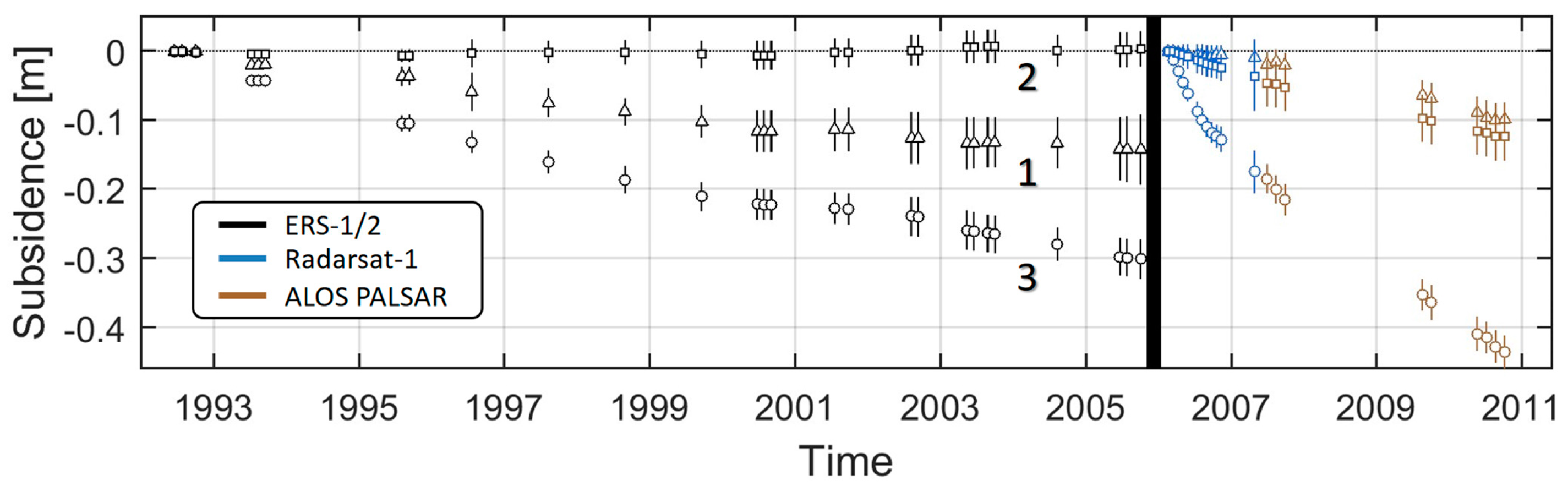
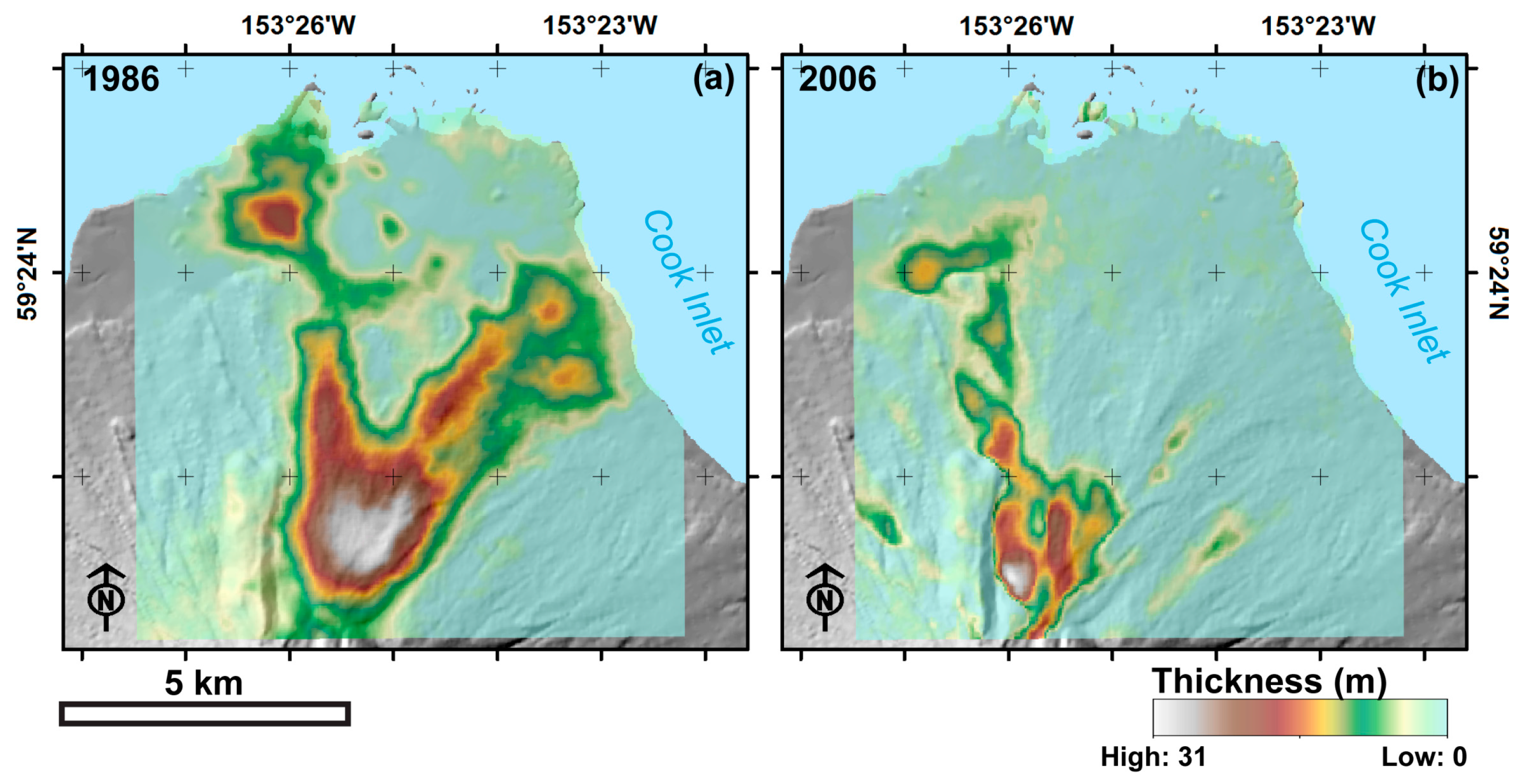
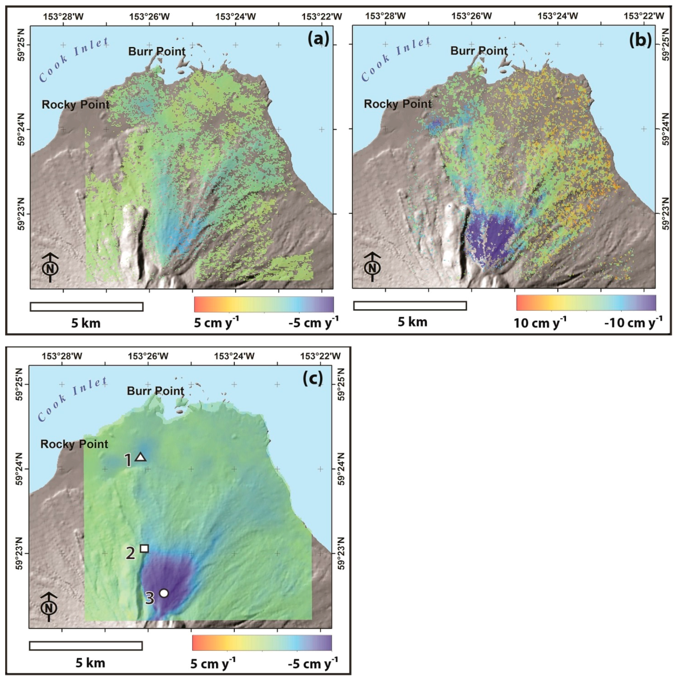
5.1. d-InSAR-Based Estimates of Surface Subsidence and 2006 PFD Thickness

We estimated s n 92 05 , s n 06 07 , and s n 07 10 , and 2006 PFD thickness h P F D , 06 by applying the techniques in Section 4.1 to a total of 48 single look complex (SLC) SAR images. Subsidence estimates s n 92 05 were based on a stack of 27 ERS-1/2 images acquired between the 1986 and the 2006 eruptions. s n 06 07 was estimated from 12 Radarsat-1 images acquired within the first 12 months after the 2006 eruption. The parameters s n 06 07 and h P F D , 06 were derived from nine ALOS-PALSAR images with acquisition dates between July 2007 and October 2010 (Table 1). October 2010 was the last seasonally appropriate ALOS-PALSAR acquisition of the target area. In April 2011, the ALOS satellite suffered a non-recoverable power generation anomaly. It was permanently powered down on 12 May 2011 [63].
Time-baseline plots showing the interferograms selected for the three data stacks are shown in Figure 4, along with the spatial and temporal baseline thresholds ( B t m a x and B m a x ) that were used in the interferogram selection process. Baseline thresholds were set empirically to optimize InSAR coherence and reduce the number of unconnected interferogram subsets. Note that, for the ERS-1/2 data stack, three interferograms with a larger geometric baseline but with good coherence were added to the data set to keep the number of unconnected interferogram subsets low.
Average subsidence rates Δ s (Equation (7)) were derived for the three subsidence time series and are plotted in Figure 5a–c. For all three data sets, a spatial coherence threshold of 0.2 was set to discard incoherent regions. Coherence loss is particularly evident in the Radarsat-1 time series ( s n 06 07 ) where rapid surface change in the first months after the eruption resulted in extended no-data areas (transparent regions in Figure 5b). Figure 5 shows that largest subsidence rates are found for the time period immediately following the eruption ( Δ s 06 07 ; Figure 5b) where poroelastic and thermoelastic deformation of newly deposited 2006 materials, as well as thermoelastic deformation of underlying 1986 deposits, lead to subsidence rates of up to 20 cm·year−1. Figure 5 also demonstrates that the spatial pattern of subsidence changes after the 2006 eruption, which can be attributed to the newly deposited material.
Subsidence time series for three points on Augustine’s PFDs (indicated by rectangle, triangle and circular symbols in Figure 5c) are shown in Figure 6 as black and gray lines. To create these plots, the post-2006 deformation estimates s n 06 07 and s n 07 10 were connected using an offset parameter, estimated using least-squares techniques constrained by a minimum-norm assumption.
The black subsidence time series (lines 1 and 3) corresponds to two locations that were covered by both the 1986 and the 2006 PFDs. Correspondingly, their deformation between 1992 and 2005 relates to cooling of 1986 flows. Figure 5c illustrates that stronger deformation occurs near Augustine’s summit crater that is attributed to the area’s greater thickness of PFDs, observable in Figure 7a,b. Following deposition of the 2006 PFDs, deformation rates near the crater increased due to the combined subsidence of both 1986 and 2006 material. The subsidence time series No. 2, indicated by the gray line in Figure 6, is taken from a location that was only affected by 2006 flows (Figure 5c); consequently, surface deformation from 1992 to 2005 is zero, as expected.
In addition to surface subsidence, we estimate the thickness hPFD,06 of pyroclastic flow material deposited during the 2006 eruption using the method described in Section 4.1. Based on our error model, which considers the distribution of perpendicular baselines as well as error sources related to coherence and DEM accuracy, hPFD,06 could be estimated with an average error of σ h P F D ,   06 = 2.1   m . A map of hPFD,06 is presented in Figure 7b showing deposition predominantly in a northerly direction from the summit with thickest deposits (> 30 m) found just north of Augustine summit. We found the total volume of 2006 PFD deposits to be 3.3 × 10⁷ m3 (0.033 km3) ± 0.11 × 10⁷ m3 from these data, with a maximum thickness of ~31 m, and a mean of ~5 m.
These estimates compare well to field observations of the 2006 PFDs by Coombs et al., [34], who identified the difficulty of thickness measurements and/or estimates as a main source of uncertainty in volume and yield calculations for the 2006 eruption. With that caveat in mind, Coombs et al., estimated thicknesses ranging from sub-meter deposits on steep slopes and flow edges, to a maximum of 10–15 m in the distinctive Rocky Point pyroclastic flow; see Figure 2b and Figure 7b [12,34]. A comparison of digital terrain models of the volcano’s edifice, acquired before and after the eruption, indicates a maximum thickness of 20 m [12], and the inflated eruptive volume at ~3.9 × 10⁷ m3 (2.3 × 10⁷ m3 DRE), subject to inherent uncertainties of 25%–50% [34].

5.2. Estimated PFD Parameters for the 1986 and 2006 Deposits

5.2.1. Testing the Approximation of Linearity in the Geophysical Model

To formulate our physical deformation model in Section 4.2, we approximate the true subsidence time series s n 92 05 , s n 06 07 , and s n 07 10 by a linear model of the form s n = Δ s · t n , where Δ s are their linear subsidence rates. When analyzing the shape of the subsidence time series in Figure 6, it can be observed that the subsidence of PFDs indeed appears reasonably linear within each data stack. A chi-squared test was conducted to test if the deformation data in s n 92 05 , s n 06 07 , and s n 07 10 can be sufficiently described by a linear model. This test showed that 90% of the variability in these subsidence time series can be explained by a linear model. Furthermore, it was found that an alternative exponential decay model did not lead to a statistically significant improvement of model fit. Both of these findings indicate that approximating our data by a linear model, as suggested in Section 4.2, does not lead to significant loss of information.

5.2.2. Estimating γ ¯ t h and γ ¯ p e

We use the linear subsidence rates Δ s 92 05 , Δ s 06 07 , and Δ s 07 10 together with estimates for the thermoelastic and poroelastic contraction parameters γ ¯ t h and γ ¯ p e , respectively. As we assume that the subsidence measurements in the individual pixels are uncorrelated from measurements in other pixels (see Section 4.1 and Section 4.2), this means that the model in Equations (10)–(14) can be executed pixel by pixel, vastly simplifying the computational complexity. While there are true correlations between pixels (related to phase filtering and atmospheric effects), we considered the impact of ignoring these correlations small compared to the impact on computational efficiency.
Before inverting for parameters γ ¯ t h and γ ¯ p e we first conducted a test of the geophysical relationships in Equation (8), which imply a linear relationship between surface contraction rate, Δ s , and PFD thickness h , with γ ¯ t h and γ ¯ p e acting as scaling parameters. To test this assumption, we created a scatterplot between the surface subsidence ( Δ s 07 10 Δ s 92 05 ) and thickness h P F D , 06 of the 2006 PFDs (Figure 8). The result showed a strong linear correlation between subsidence rate and PDF thickness ( r 2 = 0.66 ), giving credence to the scaling model used in Equations (8)–(10). Similar linear relationships were also found by Ebmeier et al., [55], who studied deformation of a lava flow deposit at Santiaguito Volcano, Guatemala.
With the assumptions in our geophysical model confirmed, we perform the least-squares estimation of the thermoelastic and poroelastic contraction parameters γ ¯ t h and γ ¯ p e using the formalism in Equations (9)–(13). The following results were achieved:
Least Squares Estimates for γ ¯ t h and γ ¯ p e :
  • γ ¯ t h (cm·year−1·m−1) = −0.091; sigma = 0.002
  • γ ¯ p e (cm·year−1·m−1) = −0.319; sigma = 0.005
    Correlation coefficient between parameters = −0.22
These results indicate that both γ ¯ t h and γ ¯ p e could be successfully separated using the proposed approach (small correlation coefficient) with acceptable precision ( σ γ ¯ t h = 0.002 and σ γ ¯ p e = 0.005) as shown above. While only relevant for a short time period after the eruption, poroelastic contraction was dominant during the immediate post eruption time. The long term-acting thermoelastic contraction was found to cause subsidence of 0.1 cm year−1 m−1. Interestingly, this value is in good agreement with typical contraction parameters for basaltic and andesitic lava flows that were calculated by Ebmeier et al., from a limited set of global measurements [55]. This similarity should be studied further for PFDs at other volcanoes with sufficient SAR data coverage.

5.2.3. Estimating the Thickness of PFDs Deposited in 1986

Following the assumption of strong similarities between the compositions of the 1986 and 2006 PFDs (Section 2.2), we conclude that the thermoelastic contraction parameter γ ¯ t h (estimated for the 2006 PFDs in Section 5.2.2) also applies to deposits emplaced during the 1986 eruption. Consequently γ ¯ t h can be used, together with Equation (7), to arrive at first estimates of the thickness, h ^ P F D , 86 , of PFDs deposited in 1986.
We apply the general least squares concept in Equations (14) and (15) to calculate both h ^ P F D , 86 and its accuracy properties and achieved the following result:
General Least Squares Estimates for h ^ P F D , 86 :
  • mean thickness μ h ^ P F D , 86 (m) = 7.4
  • error of thickness estimates σ h ^ P F D , 86 (m) = 1.1
  • max thickness (m) = 31.5
  • total deposition volume (m3) = 4.6 × 10⁷ ± 0.62 × 10⁷
A map of the estimated 1986 PFD thickness is shown in Figure 7a. At 4.6 × 10⁷ ± 0.62 × 10⁷ m3, we found the total volume of the 1986 PFDs to be about 1.5 times larger than those deposited in 2006. A comparison of the maps in Figure 7a,b shows that this difference mainly stems from a higher deposition on the northeastern flank of Augustine during the 1986 eruption. To estimate the average deposition thickness μ h ^ P F D , 86 we first identified pixels with significant deposition by applying a threshold of h ^ P F D , 86 < 2 · σ h ^ P F D , 86 and then calculated the average of h ^ P F D , 86 over these pixels. As the resulting number μ h ^ P F D , 86 = 7.4 m is dependent on the selected threshold, it should be considered as an approximate value only.
By comparison, Swanson and Kienle [64] estimated the expanded volume of the 1986 PFDs as approximately 5 × 10⁷ m3 (0.05 km3), but did not describe how that estimate was determined. They also report that a post-eruption topographic map, prepared from aerial photographs taken on 9 September 1986, indicated that dome elevation had increased by ~26 m between 1976 and the close of the 1986 eruption (consistent with Waitt and Begét’s observation, between 1992 and 2003, of a 1986 andesite dome forming a prominent part of the summit area [28]). More recently, a finite element model developed by Masterlark et al., [20], predicted PFDs with a mean thickness of 9.3 m, a maximum of 126 m, and a volume of 2.1 × 10⁷ m3 (0.021 km3); Masterlark et al., similarly report a total PFD volume of 9.9 × 10⁶ m3 (~0.01 km3) estimated by differences in DEMs. A summary of the available values is presented in Table 2.
Our estimates of thickness and volume for 1986 compare well to the 1986 topographic map and observations reported by Swanson and Kienle [64], but differ more significantly from the results modeled by Masterlark et al., [20]. Given the observations of dome growth by Swanson and Kienle [64] and Waitt and Begét [28], however, it seems fair to attribute differences in maximum thickness, particularly in the area proximal to the summit, to andesitic dome growth rather than PFDs alone. Differences in volume are likely due to uncertainties of the finite element model used by Masterlark, et al., [20]. While these uncertainties are not numerically specified, model runs with different initial parameter settings resulted in PFD volume estimates ranging from 9.9 × 10⁶ m3 to 5.7 × 10⁷ m3 encompassing our result.

6. Discussion

6.1. Limitations of the Technique

Thickness and deformation rates were developed from models based on observations and a number of simplifying assumptions. Chief among these is an assumption that Augustine’s 1986 and 2006 PFDs were sufficiently similar to allow modeling using the same material parameters. The eruption dynamics and a comparison of whole-rock geochemical composition (Figure 3) served as the basis for this general assumption. Although we believe this compositional comparison was sufficient for the stated purpose, it was not intended to be a comprehensive geochemical analysis, which was beyond the scope of this work. Similarly, we broadly considered the principal mechanism of deformation to be thermoelastic contraction (Section 4.2.1). Given the similarity of the two eruptions and eruptive products, we considered it unnecessary to model individual deformation processes such as cooling and degassing, or individual conditions that contribute to that process (porosity, density, pressure, and others). This necessarily involves an additional, implicit assumption that the PFDs from 1986 and 2006 were homogeneous in composition, allowing for uniform rates of deformation. This assumption was made despite field observations that Augustine’s 1986 PFDs were comprised of block and ash flow deposits, lithic-rich pumice flow deposits, and lahar deposits [65], and deposits from 2006 were similar to 1986 in terms of sequence, deposit distributions, and magma compositions [12,34,35,64]. These observations may indicate the possibility of depositional gradations that refute the assumption of uniform deformation. We, however, believe the relative similarities between the two years’ eruption products and their similarly rapid emplacement process validate the uniformity assumption for purposes of this estimation.
To simplify modeling and data interpretation, we approximated the deformation behavior of PFDs at Augustine as a piecewise linear process where an initial (higher) deformation rate describes the deformation during the first months after emplacement and a second rate represents the long-term deformation as a flow. This differs from most other approaches, which often use exponential decay functions to describe the temporal variation of subsidence [54]. We showed in Section 5.2.1 that using exponential functions did not lead to a statistically significant improvement of model fit to the InSAR data. Furthermore, we also found that the parameters of the linear functions could be estimated with higher significance than the parameters of an alternative exponential function. Hence, linear models were considered sufficient for this study.

6.2. Scientific Significance of Extracted PFD Information

Deformation behavior of volcanic deposits, although reasonably well understood, is difficult to observe and measure on a first hand, in situ basis. Obtaining data from direct observation of pyroclastic emplacement may be hampered by continuing volcanic activity, remote locations, arduous terrain, and other obstacles. Numerical modeling has proven highly effective in estimating deformation, particularly when geometric data, such as deposit thickness from repeated DEMs, are unavailable [20]. Modeling, however, may require significantly simplifying assumptions, and be valid only for individual field situations [66]. The results from our study, such as deposit thickness and deformation, can provide an important method to numerical modeling and help increase the reliability and precision of geophysical estimates.
The technique we present offers a means to estimate PFD thickness and deformation rates using InSAR and parameter estimation techniques that reach beyond a priori estimates and initial modeling. By decomposing contributions from multiple generations of PFDs, our approach provides a basis to quantify thickness, deformation rates, and volume of recent deposits, while providing some insight into a volcano’s past by providing previously inaccessible information about deposits from earlier eruption cycles. More precise and accurate data on the post-emplacement characteristics of PFDs allow geophysical parameters to be more accurately modeled, and improve the body of knowledge available for investigation of volcanic hazards.

7. Conclusions

This study combines 16 years of InSAR data from multiple platforms to study the thickness and long-term subsidence behavior of PFDs from Augustine Volcano. Our methodology was applied to examine the subsidence behavior of PFDs from multi-sensor InSAR acquisitions acquired across two eruption cycles. This includes a model used to decompose deformation signals from two generations of superimposed flows. From this model, we are able to present the reconstructed subsidence history for PFDs observed on Augustine Island.
This investigation provides interesting insight into post-emplacement behavior of PFDs and similar eruptive flows. Using empirical observations derived from SAR data, we determined that the initial settling period is usually concluded within a year of emplacement. We were also able to show a decrease of deformation rates over time as cooling rates of the flows subside. The produced results allow us to better understand the behavior and geometry of PFDs by using InSAR. Masterlark et al., has previously demonstrated that thermoelastic deformation is a strong function of PFD thickness [20], and used finite element modeling and an adaptive mesh algorithm to produce a thickness distribution of PFDs from Augustine’s 1986 eruption. Using InSAR data from Augustine’s 2006 eruption, our model describes a relationship between the thickness of PFDs, their material properties, deformation rates, and change in temperature that permits estimation of any of these four parameters when the other three are known or similarly estimated. Finally, the model can be extended to underlying PFDs to estimate the effect of deforming materials deposited by prior eruptions.

Acknowledgments

This study was funded in part by NASA grant ID: NNX12AQ38G. The authors wish to thank Cynthia Gardner of the USGS Cascades Volcano Observatory for providing geochemical data on Augustine Volcano’s 1986 eruptive products. ALOS-PALSAR data were provided by JAXA as ALOS high level products, ©JAXA, METI, ALOS-1, PALSAR L1.0 2007–2010. Datasets from ERS-1, ERS-2, RADARSAT-1, and ALOS-PALSAR were retrieved from the Alaska Satellite Facility (ASF) Distributed Active Archive Center (DAAC) 2013–2015, and provided through the NASA Earth Science Data and Information System (ESDIS) project. SRTM data were provided courtesy of the USGS Earth Resources Observation and Science Center (EROS), Sioux Falls, South Dakota. The authors gratefully acknowledge the suggestions and comments of four anonymous reviewers that significantly improved the initial manuscript.

Author Contributions

D.B.M. and F.J.M. conceived and designed this study, and wrote the paper. W.G. retrieved and processed SAR data. J.E.B. and P.W.W. contributed interpretation and participated in all results. F.J.M. supervised the entire project.

Conflicts of Interest

The authors declare no conflicts of interest.

Appendix A

Table A1. Definitions of variables used in Section 4, Equations (1)–(16).
VariableDescription
NThe number of acquisition times of SAR images in a time series [t0,…tN]. The series starts at zero, resulting in a stack of N + 1 images.
ϕ i , j The interferometric phase measurement [rad] in each pixel, calculated from the SAR images i and j (i.e., an interferogram).
ϕ i , j , d e f o The contribution of ground deformation to each pixel that occurred between time t i and t j .
ϕ i , j , t o p o The topography-related phase component that is proportional to the surface height and the interferometric baseline between acquisition at times t i and t j .
Δ d i , j The surface deformation [m] that occurred between image acquisition times t i and t j .
ϕ i , j , a t m s Interferometric phase related to changes in the atmospheric stratification between times t i and t j .
ϕ i , j , a t m t Phase differences from variations in the distribution of atmospheric water vapor at time t i and t j .
ϕ i , j , o r b i t The interferometric phase contribution due to errors in the satellite orbits of acquisitions at times t i and t j .
ϕ i , j , n o i s e Phase noise in a pixel of an interferogram calculated from acquisitions at times t i and t j .
h The SAR-observed surface topography [m].
Δ Φ i , j The unwrapped differential interferometric phase of a pixel in SAR images i and j.
d n The cumulative surface deformation of PDFs across the time-series d 0 d n .
r The sensor-to-target range between a SAR instrument and its ground target.
B i , j , The perpendicular baseline distance between sensor acquisitions i and j.
θ The look angle of the SAR system.
λ The wavelength of the transmitted radar signal.
h p e Topography values obtained from a pre-eruption DEM.
h P F D , 06 The thickness of 2006 PFDs measured by InSAR.
B n , The perpendicular baseline between the SAR image acquisition at time t n and the reference image acquisition at time t 0 .
Δ φ n The reconstructed phase history at the N+1 image acquisition times.
B t The temporal baseline of an InSAR image pair.
Δ φ n The reconstructed phase history at time step n of the N + 1 image acquisitions.
Δ φ The (N × 1) vector of reconstructed phase history values.
d n 92 05
d n 06 07
d n 07 10
Deformation time series data estimated for the time periods 1992–2005 (ERS1 and 2), 2006–2007 (Radarsat-1), and 2007–2010 (ALOS PALSAR) (see also s n 92 05 , et al.).
s n 92 05
s n 06 07
s n 07 10
Deformation time series data estimated for the time periods 1992–2005 (ERS 1 and 2), 2006–2007 (Radarsat-1), and 2007–2010 (ALOS PALSAR) after projection into a joint vertical reference frame (see dn92-05, et al.).
Δ s n 92 05
Δ s n 06 07
Δ s n 07 10
Estimated linear subsidence rates applicable to each of the three time series, s n 92 05 , s n 06 07 , s n 07 10 .
Δ s Linear subsidence rate.
h P F D , 86 The unknown thickness of the 1986 PFDs.
γ ¯ t h The average thermoelastic contraction parameter of PFDs for the 2006–2007 period.
k ¯ The average cooling rate of 2006 PFDs.
γ ¯ p e The average poroelastic contraction parameter of PFDs for the 2006–2007 period.
α L The thermal contraction coefficient of the PFDs.
b The (2·R·C) × 1 column vector of observations in the InSAR data matrix.
ε ^ The (2·R·C) × 1 column vector of estimated residuals.
x ^ Generic vector of estimated unknowns in a least-squares inversion framework.
A Design matrix of a least-squares inversion framework, containing the partial derivatives of a mathematical relationship relative to the unknowns.
P b b Weight matrix.
Σ b b The covariance matrix of observations.
δ The object function to be minimized in a least-squares inversion.
Σ x ^ x ^ The covariance matrix of estimated unknowns x ^ .
B A second design matrix of the generalized least-squares model containing the partial derivatives of a mathematical relationship with respect to the observations.

References

  1. Gabriel, A.K.; Goldstein, R.M.; Zebker, H.A. Mapping small elevation changes over large areas: Differential radar interferometry. J. Geophys. Res. 1989, 94, 9183–9191. [Google Scholar] [CrossRef]
  2. Massonnet, D.; Feigl, K. Radar interferometry and its application to changes in the earth's surfaces. Rev. Geophys. 1998, 36, 441–500. [Google Scholar] [CrossRef]
  3. Mouginis-Mark, P.J.; Domergue-Schmidt, N. Acquisition of satellite data for volcano studies. Remote Sens. Active Volcanism 2000, 9–24. [Google Scholar]
  4. Rosen, P.A.; Hensley, S.; Joughin, I.R.; Li, F.K.; Madsen, S.N.; Rodriguez, E.; Goldstein, R.M. Synthetic aperture radar interferometry. Proc. IEEE 2000, 88, 333–382. [Google Scholar] [CrossRef]
  5. Masterlark, T.; Lu, Z. Transient volcano deformation sources imaged with interferometric synthetic aperture radar: Application to Seguam Island, Alaska. J. Geophys. Res. Solid Earth 2004, 109. [Google Scholar] [CrossRef]
  6. Rosen, P.; Hensley, S.; Zebker, H.; Webb, F.; Fielding, E. Surface deformation and coherence measurements of Kilauea Volcano, Hawaii, from SIR-C radar interferometry. J. Geophys. Res. Planets 1996, 101, 23109–23125. [Google Scholar] [CrossRef]
  7. Zebker, H.A.; Amelung, F.; Jonsson, S. Remote sensing of volcano surface and internal processes using radar interferometry. Remote Sens. Active Volcanism 2000, 179–205. [Google Scholar]
  8. Sheridan, M.F.; Ragan, D.M. Compaction of ash-flow tuffs. Dev. Sedimentol. 1975, 18, 677–717. [Google Scholar]
  9. Riehle, J.R.; Miller, T.F.; Bailey, R.A. Cooling, degassing and compaction of rhyolitic ash flow tuffs: A computational model. Bull. Volcanol. 1995, 57, 319–336. [Google Scholar] [CrossRef]
  10. Cas, R.A.F.; Wright, J.V. Volcanic Successions, Modern and Ancient: A Geological Approach to Processes, Products and Successions; Allen & Unwin, Ltd.: London, UK, 1987. [Google Scholar]
  11. Williams, H.; McBirney, A.R. Volcanology; Free man, Cooper & Co.: San Francisco, CA, USA, 1979. [Google Scholar]
  12. Vallance, J.W.; Bull, K.; Coombs, M.L. Pyroclastic Flows, Lahars, and Mixed Avalanches Generated During the 2006 Eruption of Augustine Volcano; Power, J., Coombs, M.L., Freymueller, J., Eds.; United States Geological Survey: Reston, VA, USA, 2010; pp. 219–267.
  13. Stevens, N.F.; Wadge, G.; Williams, C.A.; Morley, J.G.; Muller, J.P.; Murray, J.B.; Upton, M. Surface movements of emplaced lava flows measured by synthetic aperture radar interferometry. J. Geophys. Res. Solid Earth 2001, 106, 11293–11313. [Google Scholar] [CrossRef]
  14. Lu, Z.; Masterlark, T.; Dzurisin, D. Interferometric synthetic aperture radar study of Okmok volcano, Alaska, 1992–2003: Magma supply dynamics and post-emplacement lava flow deformation. J. Geophys. Res. 2005, 110. [Google Scholar] [CrossRef]
  15. Briole, P.; Massonnet, D.; Delacourt, C. Post-eruptive deformation associated with the 1986–1987 and 1989 lava flows of Etna detected by radar interferometry. Geophys. Res. Lett. 1997, 24, 37–40. [Google Scholar] [CrossRef]
  16. Schmincke, H.U. Volcanism; Springer: New York, NY, USA, 2004. [Google Scholar]
  17. Waitt, R.B.; McIntire, J.; Janda, C.G. Geologic Map of Augustine Island, Alaska-Plate 1, 1:25,000; Waitt, R.B., Begét, J., Eds.; United States Geological Survey: Reston, VA, USA, 2009.
  18. Coombs, M.L.; Bull, K.; Vallance, J.W.; Thoms, E.E. Geologic Map of On-Island Deposits from the 2006 Eruption of Augustine Volcano (Map)-Plate 1, 1:20000; Power, J.A., Coombs, M.L., Freymueller, J., Eds.; United States Geological Survey: Reston, VA, USA, 2010.
  19. Rowley, P.D.; Kuntz, M.A.; Macleod, N.S. Pyroclastic-flow deposits. In The 1980 Eruptions of Mount St. Helens; Lipman, P.W., Mullineaux, D.R., Eds.; United States Geological Survey: Reston, VA, USA, 1981; pp. 489–512. [Google Scholar]
  20. Masterlark, T.; Lu, Z.; Rykhus, R. Thickness distribution of a cooling pyroclastic flow deposit on Augustine Volcano, Alaska: Optimization using InSAR, FEMs, and an adaptive mesh algorithm. J. Volcanol. Geotherm. Res. 2006, 150, 186–201. [Google Scholar] [CrossRef]
  21. Riehle, J.R. A reconnaissance of the major Holocene tephra deposits in the upper Cook Inlet region, Alaska. J. Volcanol. Geotherm. Res. 1985, 26, 37–74. [Google Scholar] [CrossRef]
  22. Zielinki, S. Explosion at dormant Alaskan volcano. Eos. Trans. Am. Geophys. Union 2006, 87, 435. [Google Scholar] [CrossRef]
  23. Neal, C.A.; McGimsey, R.G.; Dixon, J.P.; Manevich, A.; Rybin, A. 2006 Volcanic Activity in Alaska, Kamchatka, and the Kurile Islands: Summary of Events and Response of the Alaska Volcano Observatory; United States Geological Survey: Reston, VA, USA, 2008.
  24. Kienle, J.; Shaw, G.E. Plume dynamics, thermal energy and long-distance transport of vulcanian eruption clouds from Augustine Volcano, Alaska. J. Volcanol. Geotherm. Res. 1979, 6, 139–164. [Google Scholar] [CrossRef]
  25. Power, J.A.; Lalla, D.J. Seismic observations of Augustine Volcano, 1970–2007. In The 2006 Eruption of Augustine Volcano, Alaska; Power, J., Coombs, M.L., Freymueller, J., Eds.; United States Geological Survey: Reston, VA, USA, 2010; pp. 3–40. [Google Scholar]
  26. Yount, M.E.; Miller, T.P.; Gamble, B.M. The 1986 eruptions of Augustine Volcano, Alaska: Hazards and effects. In Geologic Studies in Alaska in 1986; Hamilton, T.D., Galloway, J.P., Eds.; United States Geological Survey: Reston, VA, USA, 1987; pp. 4–13. [Google Scholar]
  27. Miller, T.P.; McGimsey, R.G.; Richter, D.H.; Riehle, J.R.; Nye, C.J.; Yount, M.E.; Dumoulin, J.A. Catalog of the Historically Active Volcanoes of Alaska; United States Geological Survey: Reston, VA, USA, 1998.
  28. Waitt, R.B.; Begét, J. Volcanic Processes and Geology of Augustine Volcano, Alaska—Plate 2, 1:25,000; United States Geological Survey: Reston, VA, USA, 2009.
  29. Siebert, L.; Glicken, H.; Kienle, J. Debris avalanches and lateral blasts at Mount St. Augustine Volcano, Alaska. Natl. Geogr. Res. 1989, 5, 232–249. [Google Scholar]
  30. Begét, J.E.; Kowalik, Z. Confirmation and calibration of computer modeling of tsunamis produced by Augustine Volcano, Alaska. Sci. Tsunami Hazards 2006, 24, 257–266. [Google Scholar]
  31. Davidson, G. Notes on the eruption of Mount St. Augustine, Alaska, Oct. 6, 1883. Science 1884, 3, 186–189. [Google Scholar] [CrossRef] [PubMed]
  32. United States Geological Survey (USGS): Geographic Names Information System. Available online: http://geonames.usgs.gov/apex/f?p=136:3:0::NO:3:P3_FID,P3_TITLE:1412986,Nanwalek (accessed on 7 September 2016).
  33. Kienle, J.; Kowalik, Z.; Murty, T.S. Tsunamis generated by eruptions from Mount St. Augustine Volcano, Alaska. Science 1987, 236, 1442–1447. [Google Scholar] [CrossRef] [PubMed]
  34. Coombs, M.L.; Bull, K.; Vallance, J.W.; Schneider, D.; Thoms, E.E.; Wessels, R.L.; McGimsey, R. Timing, distribution, and volume of proximal products of the 2006 eruption of Augustine Volcano. In The 2006 Eruption of Augustine Volcano, Alaska; Power, J.A., Coombs, M.L., Freymueller, J., Eds.; United States Geological Survey: Reston, VA, USA, 2010; pp. 145–185. [Google Scholar]
  35. Power, J.A.; Nye, C.J.; Coombs, M.L.; Wessels, R.L.; Cervelli, P.F.; Dehn, J.; Wallace, K.L.; Freymueller, J.T.; Doukas, M.P. The reawakening of Alaska’s Augustine Volcano. Eos Trans. AGU 2006, 87, 373–377. [Google Scholar] [CrossRef]
  36. Cervelli, P.F.; Fournier, T.; Freymueller, J.; Power, J.A. Ground deformation associated with the precursory unrest and early phases of the January 2006 eruption of Augustine Volcano, Alaska. Geophys. Res. Lett. 2006, 33. [Google Scholar] [CrossRef]
  37. Curlander, J.C.; McDonough, R.N. Synthetic Aperture Radar: Systems and Signal Processing; John Wiley & Sons, Inc.: New York, NY, USA, 1991. [Google Scholar]
  38. Larsen, J.F.; Nye, C.J.; Coombs, M.L.; Tilman, M.; Izbekov, P.; Cameron, C. Petrology and geochemistry of the 2006 eruption of Augustine Volcano. In The 2006 Eruption of Augustine Volcano, Alaska; Power, J.A., Coombs, M.L., Freymueller, J., Eds.; United States Geological Survey: Reston, VA, USA, 2010; pp. 335–382. [Google Scholar]
  39. Gardner, C. USGS Cascades Volcano Observatory: Vancouver, WA, USA, Unpublished data; 2016.
  40. Rignot, E.J.M.; van Zyl, J.J. Change detection techniques for ERS-1 SAR data. IEEE Trans. Geosci. Remote Sens. 1993, 31, 896–906. [Google Scholar] [CrossRef]
  41. Morena, L.C.; James, K.V.; Beck, J. An introduction to the RADARSAT-2 mission. Can. J. Remote Sens. 2004, 30, 221–234. [Google Scholar] [CrossRef]
  42. European Space Agency: Observing the Earth. Available online: http://www.esa.int/Our_Activities/Observing_the_Earth/ERS_overview (accessed on 25 September 2014).
  43. Rosenqvist, A.; Shimada, M.; Ito, N.; Watanabe, M. ALOS PALSAR: A pathfinder mission for global-scale monitoring of the environment. IEEE Trans. Geosci. Remote Sens. 2007, 45, 3307–3316. [Google Scholar] [CrossRef]
  44. Van Zyl, J.J. The Shuttle Radar Topography Mission (SRTM): A breakthrough in remote sensing of topography. Acta Astronaut. 2001, 48, 559–565. [Google Scholar] [CrossRef]
  45. Rodriguez, E.; Morris, C.S.; Belz, J.; Chapin, E.; Martin, J.; Daffer, W.; Hensley, S. An Assessment of the SRTM Topographic Products; Jet Propulsion Laboratory: Pasadena, CA, USA, 2005. [Google Scholar]
  46. Gong, W.; Meyer, F.J.; Lee, C.W.; Lu, Z.; Freymueller, J. Measurement and interpretation of subtle deformation signals at Unimak Island from 2003 to 2010 using weather model-assisted time series InSAR. J. Geophys. Res. Solid Earth. 2015, 120, 1175–1194. [Google Scholar] [CrossRef]
  47. Gong, W.; Meyer, F.J.; Liu, S.; Hanssen, R.F. Temporal filtering of InSAR data using statistical parameters from NWP models. IEEE Trans. Geosci. Remote Sens. 2015, 53, 4033–4044. [Google Scholar] [CrossRef]
  48. Goldstein, R.M.; Werner, C.L. Radar interferogram filtering for geophysical applications. Geophys. Res. Lett. 1998, 25, 4035–4038. [Google Scholar] [CrossRef]
  49. Costantini, M. A novel phase unwrapping method based on network programming. IEEE Trans. Geosci. Remote Sens. 1998, 36, 813–821. [Google Scholar] [CrossRef]
  50. Berardino, P.; Fornaro, G.; Lanari, R.; Sansosti, E. A new algorithm for surface deformation monitoring based on small baseline differential SAR interferograms. IEEE Trans. Geosci. Remote Sens. 2002, 40, 2375–2383. [Google Scholar] [CrossRef]
  51. Agram, P.S.; Jolivet, R.; Riel, B.; Lin, Y.N.; Simons, M.; Hetland, E.; Doin, M.P.; Lasserre, C. New radar interferometric time series analysis toolbox released. Eos Trans. Am. Geophys. Union 2013, 94, 69–70. [Google Scholar] [CrossRef]
  52. Lee, C.W.; Lu, Z.; Jung, H.S.; Won, J.S.; Dzurisin, D. Surface deformation of Augustine Volcano, 1992–2005, from multiple-interferogram processing using a refined small baseline subset (SBAS) interferometric synthetic aperture radar (InSAR) approach. In The 2006 Eruption of Augustine Volcano, Alaska; Power, J.A., Coombs, M.L., Freymueller, J.T., Eds.; United States Geological Survey: Reston, VA, USA, 2010; pp. 453–465. [Google Scholar]
  53. Fattahi, H.; Amelung, F. DEM error correction in InSAR time series. IEEE Trans. Geosci. Remote Sens. 2013, 51, 4249–4259. [Google Scholar] [CrossRef]
  54. Lee, C.W.; Lu, Z.; Kwoun, O.I.; Won, J.S. Deformation of the Augustine Volcano, Alaska, 1992–2005, measured by ERS and ENVISAT SAR interferometry. Earth Planets Space 2008, 60, 447–452. [Google Scholar] [CrossRef]
  55. Ebmeier, S.K.; Biggs, J.; Mather, T.A.; Elliott, J.R.; Wadge, G.; Amelung, F. Measuring large topographic change with InSAR: Lava thicknesses, extrusion rate, and subsidence rate at Santiaguito Volcano, Guatemala. Earth Planet. Sci. Lett. 2012, 335, 216–225. [Google Scholar] [CrossRef]
  56. Lu, Z.; Wicks, C.; Power, J.A.; Dzurisin, D. Ground deformation associated with the March 1996 earthquake swarm at Akutan volcano, Alaska, revealed by satellite radar interferometry. J. Geophys. Res. Solid Earth 2000, 105, 21483–21495. [Google Scholar] [CrossRef]
  57. Lu, Z.; Masterlark, T.; Wicks, C.; Thatcher, W.; Dzurisin, D.; Power, J. Interferometric synthetic aperture radar studies of Alaska volcanoes. In Proceedings of the IEEE International Geoscience and Remote Sensing Symposium, Toronto, ON, Canada, 24–28 June 2002.
  58. Lu, Z.; Dzurisin, D.; Biggs, J.; Wicks, C., Jr.; McNutt, S. Ground surface deformation patterns, magma supply, and magma storage at Okmok volcano, Alaska, from InSAR analysis: 1. Intereruption deformation, 1997–2008. J. Geophys. Res. 2010, 115. [Google Scholar] [CrossRef]
  59. Lanari, R.; Lundgren, P.; Sansosti, E. Dynamic deformation of Etna Volcano observed by satellite radar interferometry. Geophys. Res. Lett. 1998, 25, 1541–1544. [Google Scholar] [CrossRef]
  60. Lu, Z.; Wicks Jr, C.; Dzurisin, D.; Power, J.; Thatcher, W.; Masterlark, T. Interferometric synthetic aperture radar studies of Alaska volcanoes. Earth Obs. Mag. 2003, 12, 9–18. [Google Scholar]
  61. Pauk, B.A.; Power, J.A.; Lisowski, M.; Dzurisin, D.; Iwatsubo, E.Y.; Melbourne, T. Global Positioning System (GPS) Survey of Augustine Volcano, Alaska, August 3–8, 2000: Data Processing, Geodetic Coordinates, and Comparison with Prior Geodetic Surveys; United States Geological Survey: Reston, VA, USA, 2001.
  62. Plackett, R.L. Some theorems in least squares. Biometrika 1950, 37, 149–157. [Google Scholar] [CrossRef] [PubMed]
  63. Japan Aerospace Exploration Agency: DAICHI (ALOS) Operation Completion. Available online: http://www.jaxa.jp/press/2011/05/20110512_daichi_e.html (accessed on 7 May 2012).
  64. Swanson, S.E.; Kienle, J. The 1986 eruption of Mount St. Augustine: Field test of a hazard evaluation. J. Geophys. Res. 1988, 93, 4500–4520. [Google Scholar] [CrossRef]
  65. Begét, J.E.; Limke, A.J. Density and void ratio on emplacement of a small pyroclastic flow, Mount St. Augustine, Alaska. J. Volcanism Geotherm. Res. 1989, 39, 349–353. [Google Scholar] [CrossRef]
  66. Masterlark, T. Finite element model predictions of static deformation from dislocation sources in a subduction zone: Sensitivities to homogeneous, isotropic, Poisson-solid, and half-space assumptions. J. Geophys. Res. Solid Earth 2003, 108. [Google Scholar] [CrossRef]
Figure 1. Augustine Island (59°21.6′N, 153°25.9′W) and the Cook Inlet vicinity of South-Central Alaska. Volcanos described in the text are marked by green triangles; populated places by red circles. Contour line interval is 100 m.
Remotesensing 09 00004 g001
Figure 2. The north flank of Augustine Island with pertinent deposits from the 1986 and 2006 eruptions. From 1986 (a): 86l—Lithic PFD; 86g—Dome agglutinate and proximal fall; 86p—Deposits from pumiceous pyroclastic flows, mixed flows, and lahars (modified from Waitt et al., [17]). From 2006 (b): Cpf—Continuous phase PFDs; Cpc—Continuous phase pyroclastic current deposits; Cpfw—Windy PFD; RPpf—Rocky Point PFD; Expc—Explosive-phase pyroclastic current deposit; Expf—Explosive-phase PFD; Expct—Thin explosive-phase PFDs (modified from Coombs et al., [18]). Contour lines at 50 m.
Remotesensing 09 00004 g002
Figure 3. Silica variation diagrams demonstrating general similarities of whole-rock, major element composition in pyroclastic material from Augustine’s 1986 and 2006 eruptions.
Remotesensing 09 00004 g003
Figure 4. Time and spatial baseline diagrams indicating SAR pairs selected for interferometric processing.
Remotesensing 09 00004 g004
Figure 5. Average deformation rates (Δs) obtained by InSAR time-series analysis (cm·year−1); deformation rates apply to (a) ERS-1/2 (June 1992 to October 2005); (b) Radarsat-1 (6 February–7 April); and (c) ALOS-PALSAR (July 2007 to October 2010). Locations labeled 1, 2, and 3 in (c) are data points whose deformation across each time series is plotted in Figure 6. Note that the deformation key shown for Radarsat-1 data in (b) is shown at a smaller scale than (a) or (c), to accommodate the higher subsidence that occurred immediately after the 2006 eruption.
Remotesensing 09 00004 g005
Figure 6. Subsidence measured by InSAR at each of three locations on Augustine Volcano’s North Flank. The data points (labeled 1, 2, and 3 and indicated by different symbols) correspond to locations shown in Figure 5c. Error bars indicate the precision of the measurements and points are color coded by satellite. Bold vertical bars represent dates of eruptions. Vertical bar represents the 2006 eruption.
Remotesensing 09 00004 g006
Figure 7. Thickness plot of (a) 1986 pyroclastic flow deposits and (b) 2006 pyroclastic flow deposits on Augustine Volcano’s north flank. Maximum deposits reach a thickness of ~31m (in white) near the summit crater.
Remotesensing 09 00004 g007
Figure 8. A scatter plot of deposit thickness and subsidence rates from the 2006 eruption, shown here with the best-fit linear regression line, validates the assumption of a linear relationship between the two. Density of data points is indicated by isolines (thin black lines) and changes in gray scale shading of points. The data’s r2 value of 0.66 is persuasive evidence the linearity assumption is appropriate.
Remotesensing 09 00004 g008
Table 1. SAR data used to produce interferometric data for the 1986 and 2006 Augustine volcano eruptions.
GranulePlatformDateOrbitPathFrameAscending/Descending
E1_04883_STD_F301ERS121 June 19924883229301D
E1_05384_STD_F301ERS126 July 19925384229301D
E1_06386_STD_F301ERS14 October 19926386229301D
E1_10394_STD_F301ERS111 July 199310,394229301D
E1_10895_STD_F301ERS115 August199310,895229301D
E1_11396_STD_F301ERS119 September 199311,396229301D
E1_21259_STD_F301ERS18 August 199521,259229301D
E1_21760_STD_F301ERS112 September 199521,760229301D
E2_06596_STD_F301ERS224 July 19966596229301D
E2_12107_STD_F301ERS213 August 199712,107229301D
E2_17618_STD_F301ERS22 September 199817,618229301D
E2_23129_STD_F301ERS222 September 199923,129229301D
E2_27137_STD_F301ERS228 June 200027,137229301D
E2_27638_STD_F301ERS22 August 200027,638229301D
E2_28139_STD_F301ERS26 September 200028,139229301D
E2_32648_STD_F301ERS218 July 200132,648229301D
E2_33650_STD_F301ERS226 September 200133,650229301D
E2_38159_STD_F301ERS27 August 200238,159229301D
E2_38660_STD_F301ERS211 September 200238,660229301D
E2_42167_STD_F301ERS214 May 200342,167229301D
E2_42668_STD_F301ERS218 June 200342,668229301D
E2_43670_STD_F301ERS227 August 200343,670229301D
E2_44171_STD_F301ERS21 October 20344,171229301D
E2_48680_STD_F301ERS211 August 200448,680229301D
E2_53189_STD_F301ERS222 June 200553,189229301D
E2_53690_STD_F301ERS227 July 200553,690229301D
E2_54692_STD_F301ERS25 October 200554,692229301D
R1_53774_ST6_F149R122 February 200653,774182149A
R1_54117_ST6_F149R118 March 200654,117182149A
R1_54460_ST6_F149R111 April 200654,460182149A
R1_54803_ST6_F149R15 May 200654,803182149A
R1_55146_ST6_F149R129 May 200655,146182149A
R1_55832_ST6_F149R116 July 200655,832182149A
R1_56175_ST6_F149R19 August 200656,175182149A
R1_56518_ST6_F149R12 September 200656,518182149A
R1_56861_ST6_F149R126 September 200656,861182149A
R1_57204_ST6_F149R120 October 200657,204182149A
R1_57547_ST6_F149R113 November 200657,547182149A
R1_59948_ST6_F149R130 April 200759,948182149A
ALPSRP076331180PALSAR1 July 200776332701180A
ALPSRP083041180PALSAR16 August 200783042701180A
ALPSRP089751180PALSAR1 October 200789752701180A
ALPSRP190401180PALSAR21 August 200919,0402701180A
ALPSRP197111180PALSAR6 October 200919,7112701180A
ALPSRP230661180PALSAR24 May 201023,0662701180A
ALPSRP237371180PALSAR9 July 201023,7372701180A
ALPSRP244081180PALSAR24 August 201024,4082701180A
ALPSRP250791180PALSAR9 October 201025,0792701180A
Table 2. Comparison of previously determined values for mean thickness, maximum thickness, and volume of PFDs from Augustine’s 1986 eruption. Unreported values are shown as n/r.
Our Research Swanson and Kienle [64]Masterlark et al., Model [20]Masterlark et al., DEM [20]
Mean thickness (m)7.4n/r9.3n/r
Maximum Thickness (m)31.5n/r126n/r
Volume (m3)4.6e7 5e72.1e79.9e6

