1. Introduction
Detecting building change is of great importance for the dynamic monitoring of rapidly changing urban fringe areas and urban development analysis in general. Unmanned aerial vehicles (UAVs) could provide a flexible and cost-effective solution for dynamic time-series change monitoring if change detection was less costly and time consuming. Successful change detection (CD) relies on highly accurate measurement of the relative position of multi-temporal spatial data. Therefore, highly accurate absolute position acquisition is not necessary. UAV images collected with consumer-level digital cameras have ultra-high spatial resolution in only the RGB bands. Single UAV image coverage is small, so more images must be collected to cover an area of interest. Conventional co-registration methods applied to multi-temporal UAV images obtained from these systems are inadequate, as they produce large numbers of images at varying photographical angles.
Conventional two-dimensional image-based CD methods require high co-registration accuracy between images with similar photographic angles and similar spectral responses [
1]. If they are applied to UAV images directly, CD accuracy is low. In recent years, the use of height information for building change detection has received a great deal of attention [
2,
3,
4]. Airborne light detection and ranging (LiDAR) is a commonly-used method for obtaining height information that can be used for three-dimensional CD, but the cost is usually high [
5]. By using the semi-global matching (SGM) [
6] dense image matching (DIM) algorithm, height can be obtained as supportive information for UAV image CD, resulting in more robust detection results. Volumetric change can also be detected. However, directly subtracting the digital surface model generated by DIM for UAV images may not get desired CD results because of the error in DIM results, and the co-registration accuracy is usually not high enough.
In current UAV image change detection studies, image data co-registration preprocessing for change detection can be roughly divided into two categories. One common way is using ground control points (GCP) to geo-reference images from each flight for multi-temporal UAV images via bundle adjustments (BA). This requires a large number of GCPs to meet the change detection need for co-registration accuracy. However, using large numbers of GCPs for BA requires extensive manual work, which is time-consuming and cost ineffective. In addition, the co-registration accuracy in a local area is still insufficient and not suitable for dynamic monitoring. Another category for data co-registration methods processes images from one flight as a reference flight either by free-net BA or by using GCPs for BA. Images from a following flight are matched to the reference flight images to acquire many correspondences that can act as virtual GCPs for the following flight BA [
7]. We refer to this as “separated bundle adjustment” (Sep BA) in the rest of this letter. Both categories need a final co-registration process for orthophotos and point clouds prior to CD in order to produce more accurate CD results.
We propose a novel BA strategy called united bundle adjustment (UBA) for multi-temporal UAV image co-registration. The extra registration processing of orthophotos and point clouds before CD in UBA can be omitted. GCPs are not a necessary condition for UBA, because the absolute positioning of images is of less interest as far as CD is concerned. A local coordinate system is established after UBA. If the CD results are to be integrated with a GIS system, then GCPs are needed in the BA processing in UBA. The GPS coordinates of the UAV images can be used in BA to get rough real-world coordinates, as high-accuracy absolute position is not needed for change detection. A similar BA strategy was proposed by Qin [
8]—the exterior and interior parameters of the images from the reference flight were fixed in the combined BA process, indicating that prior weights for the observation approach infinity, while in our method, all observations were assigned the same weight.
2. Materials and Methods
2.1. Experimental Data
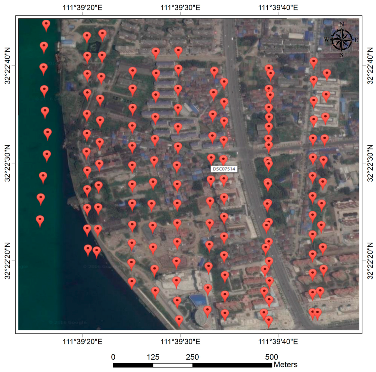
Two UAV flight images of Laohekou city, Hubei province, China were acquired in March and September 2016 using a cruising flying mode. The on-board camera was a SONY NEX-7 with a focal length of 16 mm and a pixel size of 6000 by 4000 pixels. Two flights yielded 149 images. Each flight included six strips with an overlap of about 80% in the forward direction and about 40% in the side direction. The ground sample distance of the images was approximately 0.05 m and the above ground altitude was approximately 250 m. The GPS coordinates of each image overlaying the test site are shown in
Figure 1. The red labels are GPS coordinates of each image in
Figure 1.
2.2. Methods
2.2.1. Implementation of United Bundle Adjustment
Successful CD demands high co-registration accuracy between images. Time consuming GCP BA for every flight can achieve global co-registration by geo-referencing the multi-temporal UAV images. In some local areas where there are no GCPs, the GCP BA results may suffer from huge misalignment. The Sep BA also cannot guarantee the co-registration accuracy of local areas for the same reason. An extra co-registration process before CD for the orthophoto and the point cloud generated after both GCP BA and Sep BA is needed.
To increase accuracy and bypass this extra co-registration process, we treat multi-temporal UAV images from both flights in one single processing step. We use the traditional photogrammetric aerial triangulation processing method for multi-temporal UAV images since the data is acquired in a traditional strip-by-strip way. Pair-wise image matchings are first calculated using supplementary GPS information gathered during image acquisition. Matching between images is based on the scale-invariant features transform (SIFT) [
9] performed by the SiftGPU [
10] to speed up the whole process.
We use random sample consensus (RANSAC) and relative orientation for gross matching error detection. RANSAC was first used to detect obvious outliers. The matched points were iterated using relative orientation to remove y-parallax points greater than three times the standard error. We turned the pair-wise matched points into multi-image tie points, thus forming a tie point net. One single BA process is performed for the tie point net from a set of multi-temporal UAV images, and a unified coordinate system automatically accomplishes high co-registration accuracy. We term this proposed method united bundle adjustment (UBA). In UBA, GCPs can be omitted in the BA process.
The BA process can be defined as follows: Assume there are
aerial triangulation points in a total number of
images, and
is the observation of point
on image
. Let
equal 1 if point
is visible on image
, and 0 otherwise. The exterior and interior camera parameters of image
are defined as a vector
, and each aerial triangulation points 3D coordinates as
, BA minimizes the total reprojection error defined as Equation (1):
where
is the predicted reprojection of point
on image
, and
denotes the distance between the image points
and
. Non-linear optimization BA is performed by pba software [
11]. BA processes are essentially no different for UBA, Sep BA, and GCP BA. The greater connectivity of tie points in UBA, however, ensures that the final BA results from UBA are more robust.
2.2.2. Change Detection Using Height and Image
We acquire three-dimensional height information for buildings to facilitate CD using any DIM method such as SGM for UAV images. Because multi-temporal UAV images have the same coordinate system after UBA, there is no need to further co-register orthophotos or point clouds. We adopt the CD method proposed by Tian et al. [
4] based on fusion change indicators (CI) for robust height changes and Kullback–Leibler divergence changes between images. The value for robust height change is calculated using the point-cloud-derived digital surface models with a window size of 7 × 7.
In urban areas, the height difference may be caused by the seasonal changes in trees that affect building CD results, especially when trees are near buildings. Since UAV images usually contain only visual RGB bands, we use the color vegetation indices
[
12] to acquire a vegetation mask image by applying zero as threshold on the indices according to the reference. We then use this mask image to mask out vegetation coverage. The indices are defined as follows:
where
,
and
.
,
, and
are defined as:
,
,
, where
R,
G, and
B are the original pixel value from images.
Finally, we use data fusion to fuse these CIs. The details of the CD method are found in the references.
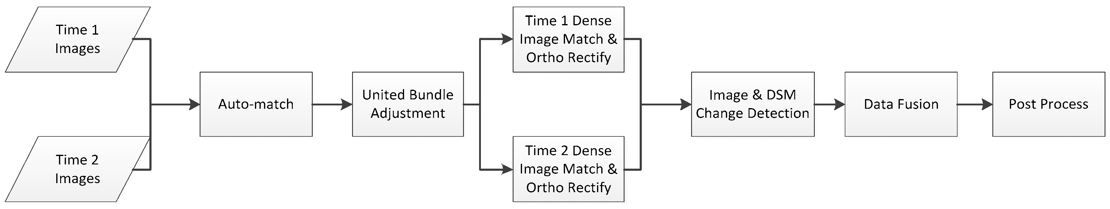
A workflow chart for UBA-based CD is shown in
Figure 2.
Taking a typical CD process for multi-temporal UAV images with only two temporal flights as a scenario, UBA-based CD can be summarized as follows: (1) Images from both flights are pair-wise matched using GPS coordinates constraints to reduce matching time; (2) UBA is performed on one single net of image tie points; (3) DIM and ortho-rectification for each image from both flights is performed separately; (4) Perform change detection using both orthophoto and a digital surface model (DSM) as derived from DIM results; (5) Data fusion and post-processing are performed to refine CD results.
3. Results
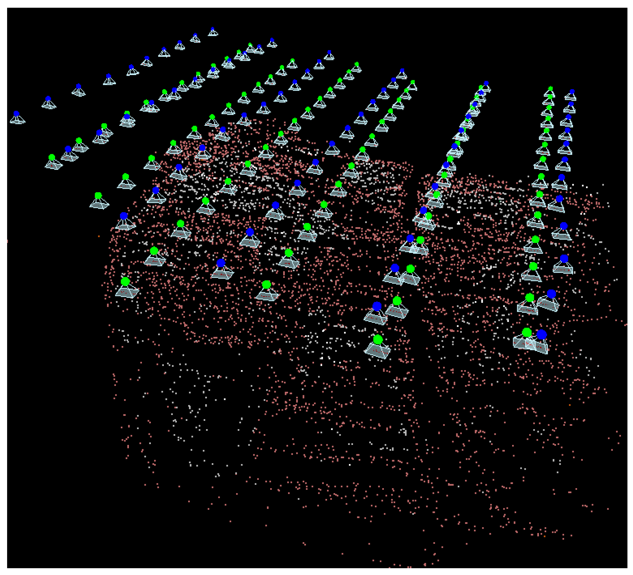
Final UBA aerial triangulation results are shown in
Figure 3. The green dots are images from the reference flight and the blue dots are images from the following flight. The underlying points are aerial triangulation points. The GSD of the final orthophotos is set to be one in pixel unit, which is approximately 0.05 m.
The proposed UBA, Sep BA, and GCP BA used the same matched tie points in order to reduce the effect of different tie points on bundle adjustment calculation. Every tie point has its unique identity. We used all tie points to perform BA in UBA. Since the two flights shared a single set of aerial triangulation points coordinates in UBA, in order to demonstrate the co-registration accuracy, we first rectified the images, and then measured the planar coordinates of the check points on the orthophotos. There were 12,705 aerial triangulation points in total. We selected 220 tie points distributed evenly in whole flight coverage as check points, and calculated the difference between planar coordinates to estimate co-registration accuracy. Height coordinates were acquired using forward intersection. Each check point was verified manually to ensure it was in fact a true corresponding point on the ground. For Sep BA and GCP BA, we first separated the whole tie point net by different flights and removed the unconnected points remaining in the single flight tie points net, then performed BA for each single flight. In Sep BA, we first performed free net BA on the reference flight to generate aerial triangulation points. We then used aerial triangulation points from the reference flight—which were in correspondence with the following flight—as the virtual GCPs for the following flight BA process.
In our experiment, half of all the tie points appearing in both flights were randomly chosen as virtual GCPs. The other half were selected as check points to compare coordinates for co-registration accuracy. We used no GCPs in UBA and Sep BA, and five GCPs in GCP BA. The unit of measurement for the GCP BA results was meters. For ease of comparison, we converted units from meters to pixels using the average photo scale. CD was performed directly on the orthophotos and point clouds generated after each BA process, without further co-registration.
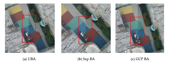
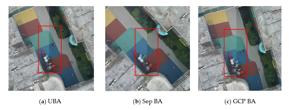
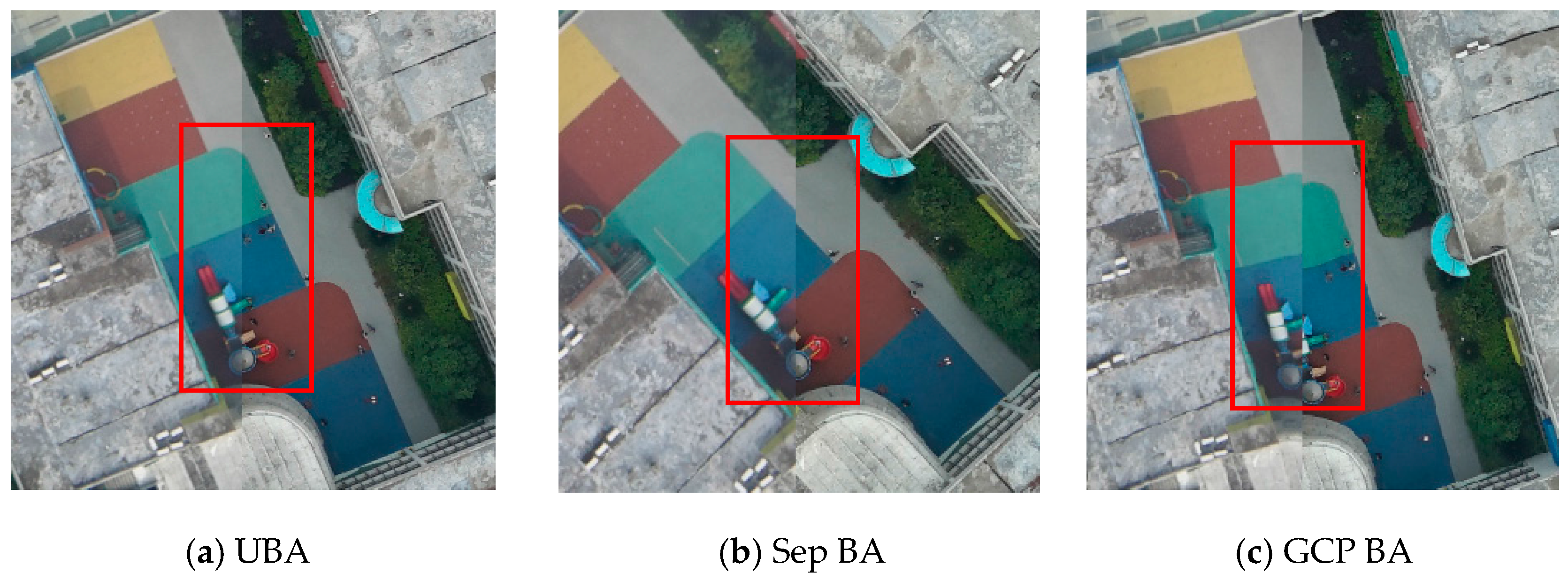
Figure 4 shows orthophoto alignment results after applying the three BA strategies. The left sides of each of the three subsets in
Figure 4 are orthophotos from the reference flight, and the right sides are orthophotos from the following flight. From
Figure 4a, we can see that the line on the ground is well aligned, indicating high co-registration accuracy. In
Figure 4b, there is a small misalignment on the ground in the Sep BA results, but this misalignment is not significant. The co-registration accuracy from GCP BA as shown in
Figure 4c was the lowest, as the circle shape is completely separated in the figure.
Table 1 shows the difference in the three-dimensional coordinates of check points as calculated using UBA, Sep BA, and GCP BA. The difference is expressed as maximum, mean, and standard deviation values. The unit of measurement for each difference is the pixel, since the BA process in UBA and Sep BA were performed on a free-network. The original unit of measurement for GCP BA check point coordinate difference was the meter, and was converted to pixels for comparison.
From
Table 1, we can see that the difference in coordinates calculated for GCP BA is the largest, because there were only five GCPs used for geo-referencing, which was insufficient for controlling the tie point net. The difference in coordinates from Sep BA was not significantly greater than UBA, because half of the tie points in both flights were used as the virtual control points for BA. The difference in coordinates from UBA was the smallest of the three methods, which is in accordance with theoretical analysis. In all three directions, UBA outperformed the Sep BA and GCP BA.
Table 2 shows statistical CD results generated for the three tested BA strategies. Because there is post-processing in CD, including morphological process, area, and shape filtering, the kappa coefficient for UBA was not significantly greater than the kappa coefficient for Sep BA. Both values were much larger than GCP BA. More details regarding the CD method can be found in reference [
4].
4. Discussion
UBA combines multi-temporal UAV images into a single match processing flow. The time interval of images acquisition should not be too long, otherwise the area of change in the image could be too large and might lead to matching failure. If such matching failure occurs in images, then a larger coverage of the imaging area is needed to ensure tie points connectivity between multi-temporal images. Since pair-wise matching is only performed on the adjacent images, the matching process time will grow linearly when the number of image sets becomes larger than two.
The co-registration accuracy for UBA is theoretically inconsistent with the BA process. More images can yield more tie points for the single bundle adjustment process in UBA. Hence, more images can theoretically generate higher co-registration accuracy. Since GCPs can be omitted in the BA process in UBA, there may be deformation in the BA system. Fortunately, CD relies on high relative co-registration accuracy; thus, the effect of deformation on CD is limited. In order to yield more robust results, it is advised to use the same well-calibrated camera to acquire UAV images and the same flight parameters for multiple flights.
Compared to traditional GCP BA and Sep BA, the aerial triangulation process for UBA is simpler and the co-registration accuracy for multi-temporal images is higher. Although bundle adjustment theory for all three BA strategies is essentially the same, co-registration preprocessing for UBA before CD is both time- and labor cost-effective, thus making UBA more applicable for UAV image-based CD for regular inspection and emergency handling in local areas.
5. Conclusions
In this letter, we propose a novel method named UBA for multi-temporal UAV image co-registration for CD. Experimental results show that UBA can achieve higher co-registration accuracy than tradition GCP BA and Sep BA methods. The difference in the coordinates of check points from UBA are within two pixels because of the stronger tie point connectivity. For short time interval dynamic monitoring in local areas, the main focus is to detect changes as quickly as possible. Since the majority of the area remains unchanged during such a short time interval, for each temporal image, if the time and labor cost is high in the preprocessing co-registration stage, then the whole dynamic monitoring would not be practical for application. Our proposed UBA method provides an easy way to complete preprocessing for change detection.
UBA combines multi-temporal UAV images into one aerial triangulation process and performs single bundle adjustment. UBA avoids separated processes and requires no extra co-registration process for orthophotos and point clouds before CD as in Sep BA and GCP BA. UBA is an application model innovation method for a particular application and can reduce the cost in labor and time for the preprocessing before CD. Therefore, UBA is suitable for dynamic monitoring. UBA preprocessing before CD promotes effective use of orthophoto, point cloud, and stereo image pairs. Post-processing is applied after initial CD in Sep BA and UBA, and the CD accuracy of UBA is not significantly better when compared to Sep BA. Yet, UBA is theoretically better for co-registration. We will carry on accuracy and reliability analysis of CD under different BA strategies in our future studies.


