1. Introduction
Microactuators are small-scale transducers that transform non-mechanical energy into mechanical work. A literature survey shows that, at the micrometer scale, electrostatic actuation is the most commonly used driving principle for these actuators [
1,
2]. This is primarily due to the favorable scaling properties of electrostatic force that allow for the generation of relatively large energy densities [
3]. In addition, electrostatic microactuators are essentially voltage driven. Consequently, fast electronic switching combined with small sizes results in fast responses and low power consumption. Lastly, one of the major reasons behind the widespread use of electrostatic microactuators is their compatibility with existing micromachining methods.
Electrostatic microactuators with relatively large output forces can be developed by exploiting the large electric fields achievable in narrow gaps [
4]. However, the achievable electric field drops off rapidly with an increase in spacing between electrodes. As a result, electrostatic microactuators with large displacement ranges generally suffer from low output forces. Electrostatic micromotors based on stepping motion [
5,
6,
7,
8,
9,
10,
11,
12,
13] are a practical solution for generating large output forces and large displacements simultaneously. These motors use a “large force-short stroke” microactuator to produce small, powerful steps. A clamping mechanism, either based on frictional force [
5,
6,
7,
8,
10,
11,
12,
13,
8,
10] or obtained with gear teeth [
9], is employed to create large displacements via incremental steps. In these motors, the propulsion and the clamping are dissociated to allow for individual optimization of these two mechanisms. These motors have inherently more accurate positioning and higher reliability than scratch drives [
14,
15,
16] and impact micromotors [
17]. They also produce larger output forces than frictionless 3-phase stepper motors [
18,
19].
To enable a further increase in output force and positioning resolution while preserving large displacement ranges, electrostatic linear stepper micromotors with a built-in mechanical leverage have been developed. Shuffle motors [
8,
10], contraction beams motors [
12] or stepper motors with an in-plane angular inflexion conversion [
13] are a few examples of such mechanisms. Shuffle motors employ electrostatic force to inflect an elastic plate and generate small, powerful steps. A voltage controlled clamping mechanism is employed to accumulate steps in sequence, enabling bidirectional motion. The first shuffle motor was fabricated by a surface micromachining process using seven lithographic masks and three polysilicon device layers [
8]. The motor, measuring 400 μm × 560 μm, was driven successfully up to a speed of 0.1 mm/s, corresponding with a cycling frequency of 1.16 kHz and an average step size of 85 nm. An output force of 43 μN was achieved at driving voltages of 25 V and 40 V for the plate and clamps, respectively. The performance and reliability of the motor were limited by charge accumulation in the silicon nitride layer employed as insulation between the electrically grounded shuttle and the driving electrodes. The negative effect of charge accumulation could be ameliorated in an improved shuffle motor design [
10]. In the design, charge accumulation was avoided by allowing mechanical contacts only between electrically grounded parts. The motor, measuring 200 μm × 1500 μm, could achieve a force of 0.45 mN at driving voltages of 65 V and 150 V for the plate and clamps, respectively. A large stroke of ±100 μm was achieved. The motor was fabricated by the five-level SUMMiT V process (14 masks and five polysilicon layers), which is the most complex polysilicon surface micromachining technology reported to date [
20].
In this work, we present a new design for the shuffle motor. The shuffle motors reported in the past [
8,
10] were electrically grounded and they moved over predefined paths that served as individual counter electrodes for the plate and for the clamps. In our design, these underlying paths have been eliminated. Our motor moves over an unpatterned, electrically grounded surface, while driving voltage signals are directly applied to the plate and to the clamps. By combining this novel design with an innovative micromachining method based on vertical trench isolation [
21], we have greatly simplified the fabrication of the shuffle motors. Furthermore, we have significantly improved their overall performance characteristics and reliability. Our motor has demonstrated exceptional performance in terms of force, resolution, displacement range and speed, leading to the highest force and power densities ever reported for an electrostatic stepper micromotor, as shown in
Figure 1 (also see
Table A1). In the following sections, we present the design and fabrication of the shuffle motor and derive analytical models to predict its performance characteristics. Finally, we demonstrate stepping motion of the motor and characterize its performance in terms of speed, average step size and output force.
Figure 1.
Power-force performance of our shuffle motor (A) compared with previously published electrostatic micromotors (B-I). A: This work; B: Li
et al. (2002) [
16]; C: Sarajlic
et al. (2006) [
12]; D: de Boer
et al. (2004) [
10]; E: Yeh
et al. (2002) [
9]; F: Akiyama
et al. (1997) [
15]; G: Erismis
et al. (2008) [
13]; H: Tas
et al. (1998) [
8]; I: Kim
et al. (2005) [
11].
2. Motor Design
The shuffle motor consists of two clamps that are mechanically connected by an elastic plate, as schematically illustrated in
Figure 2.
Figure 2.
Inchworm-like walking sequence of the shuffle motor. In the “contraction” phase, the voltage sequence is as follows: (i) Only the left clamp is activated; (ii) then, a voltage applied to the plate causes its inflexion, which generates powerful longitudinal contraction; (iii) the right clamp is then activated. In the “stretching” phase, the voltage sequence is as follows: (iv) the left clamp is released; (v) the plate voltage is turned off, which causes stretching of the plate and motion of the left clamp; (vi) both clamps are activated. For further motion to the left, the sequence is repeated from step i. Conversely, to obtain motion to the right, the sequence is reversed.
The plate and clamps are electrically insulated from each other, enabling individual biasing of these components. The motor moves over an unpatterned substrate covered with an insulating layer that is electrically grounded during operation. The driving voltage signals applied to the clamps and to the plate are provided through the suspension flexures of the motor, which are not shown in
Figure 2. As described above, the elimination of the underlying electrodes is a major improvement over previously reported shuffle motors [
8,
10]. Consequently, this reduces the complexity of the fabrication process (see
Section 3 on Microfabrication). Furthermore, it allows for motion of the motor that is not confined to predefined paths. This was exploited in a shuffle motor with two degrees of freedom, as presented in [
22].
A complete walking sequence of the shuffle motor is illustrated in
Figure 2. An inchworm-like displacement is achieved by applying an appropriate voltage sequence to the clamps and plate. First, a voltage is applied between the left clamp and the grounded substrate, creating an electrostatic force in the direction normal to the substrate. The normal force induces friction in the activated clamp that prevents it from sliding (stage
i in
Figure 2). Next, a voltage is applied on the plate, causing normal inflexion of the plate. The plate brings the right clamp closer to the left one, producing a “contraction” of the motor (
ii). Since the normal inflexion of the plate is much larger than the longitudinal motion, there is a built-in mechanical leverage, resulting in a small but powerful contraction. Subsequently, the right clamp is activated to maintain its new position (
iii) and the left clamp is released (
iv). The plate is released and, by “stretching”, it pushes the left clamp outwards (
v). The actuation sequence is completed by the activation of the left clamp (
vi). The entire sequence corresponds to the leftward motion of the whole motor in a single step. By repeating the actuation sequence continuously, a large number of steps can be accumulated, resulting in a large displacement range. Bidirectional motion of the motor is simply obtained by reversing the sequence.
3. Microfabrication
A successful operation of the proposed shuffle motor requires proper electrical insulation despite the mechanical connections between the clamps and the plate. To satisfy these requirements within a minimum number of processing steps, we have combined vertical trench isolation technology with conventional surface micromachining [
21]. In this way, we propose a relatively simple fabrication process with only two low-stress polysilicon layers and four photolithography masks. This is a significant reduction in the process complexity compared with the fabrication processes reported by Tas
et al. [
8] who employed three polysilicon layers and seven masks, and de Boer
et al. [
10], who employed five polysilicon layers and 14 masks. The cross-section of the shuffle motor after release is depicted in
Figure 3. For a detailed description of all processing steps, the reader is referred to [
22].
Figure 3.
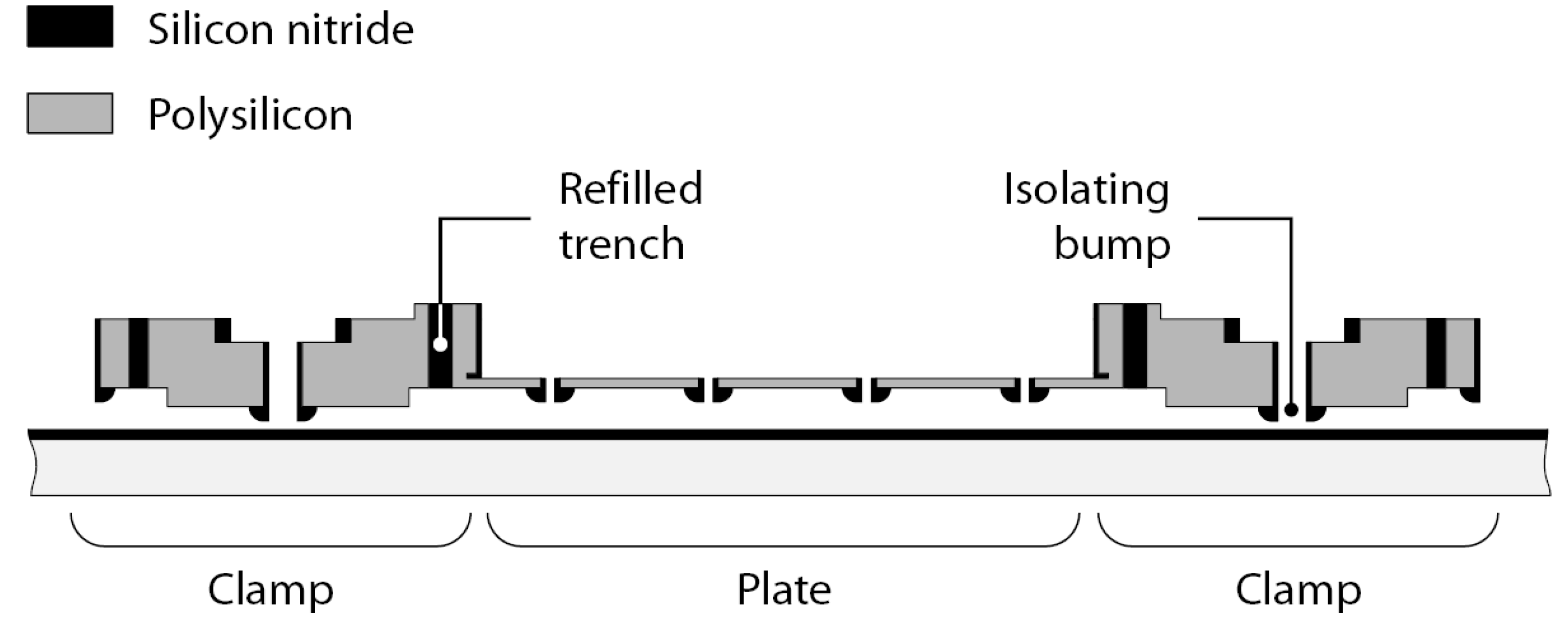
A schematic view of the cross-section of the shuffle motor. The fabrication process combines vertical trench isolation technology and surface micromachining.
Figure 3.
A schematic view of the cross-section of the shuffle motor. The fabrication process combines vertical trench isolation technology and surface micromachining.
The motor employs trenches refilled with silicon nitride to provide an electrical insulation between the clamps and the plate, enabling the independent electrical biasing of these components. At the same time, the stiffness and mechanical strength of the electrical isolation trenches ensure mechanical integrity of the device. Silicon nitride isolation bumps are evenly spaced on the backsides of the clamps and plate. These bumps significantly reduce the contact area between the device and the silicon nitride coating on the wafer surface, preventing stiction of the clamps and plate during fabrication and operation. Furthermore, the reduced contact area also reduces contact charging and charge accumulation during operation. Finally, due to the hardness of silicon nitride, its use on both sides of the contact reduces wear, increasing reliability and durability of the motor.
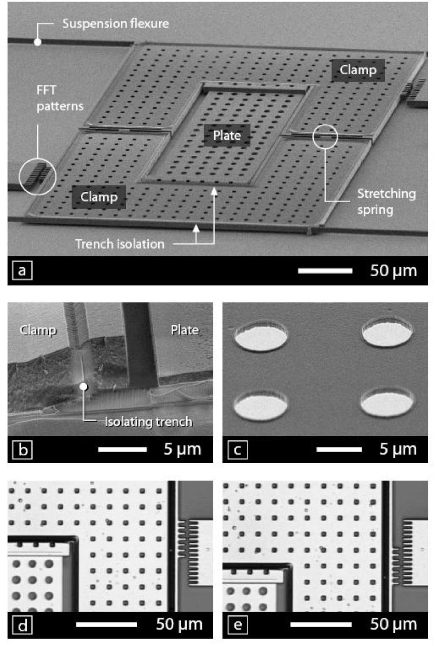
Figure 4(a) is a SEM micrograph of a fabricated shuffle motor consisting of two U-shaped clamps bridged by an elastic rectangular plate. The silicon substrate underneath the motor was coated with a 210 nm thick silicon nitride layer. The motor is suspended by four flexures (two flexures per clamp), each of which plays both a mechanical and an electrical role. Mechanically, the beams are used as flexures to ensure the linear guidance of the motor. Electrically, they serve as conductive wires transmitting the driving voltage signals to the clamps and to the plate.
Figure 4.
Micrographs of the shuffle motor. (a-c) are SEM pictures showing: (a) The shuffle motor with all components; (b) a cross-sectional view of a shuffle motor showing an isolating trench; (c) the backside of the plate with isolation bumps; (d) and (e) show operation of the motor. The repeating patterns integrated on the motor and the anchors are used for displacement measurement by Fast Fourier Transform (FFT) calculations (see details in
Section 5).
Figure 4(b) is a cross-sectional view of the motor where we can distinguish two low-stress polysilicon layers: a thin layer of 1.15 μm for the plate and a thick layer of 5.50 μm for the clamps and the flexures. The thin layer results in a rather compliant plate required for proper operation of the motor. On the other hand, the thick layer ensures the rigidity of the clamps and a large out-of-plane stiffness of the flexure beams. In our design, the flexures are not electrically shielded from the grounded substrate. Therefore, the large out-of-plane stiffness is desirable to prevent pull-down of flexures during operation of the motor. In the same image, one can see that the plate is electrically insulated from the clamps by 2 μm wide isolation trenches refilled with silicon nitride.
Figure 4(c) shows a close-up view of the isolation bumps located on the backside of the plate. Due to the rounded shape of the rim of the bumps, the contact area is significantly reduced during operation of the motor. The isolation bumps protrude from the clamps and from the plate by a height of 210 nm. This height determines the distance between the activated clamp and the coated surface and limits the maximum inflexion of the plate. A maximum inflexion of 1.55 μm was measured for an initial air gap of 1.76 μm between the plate and the substrate, a difference which corresponds with the bumps height.
The flexural suspension limits the displacement range of the shuffle motor. The maximum displacement range is determined by the total in-plane stiffness of the flexural suspension and by the maximum output force of the motor. For our measurements, we have therefore used suspensions with two types of flexures: crab-like flexures with a low in-plane stiffness to enable a large displacement range; and guided-end beam flexures with a high in-plane stiffness to enable force measurements over a wide range of output forces. We have also built three types of shuffle motors (types I, II and III) with variations in the plate length and in the clamps areas. The main dimensions of the fabricated motors are given in
Table 1.
Table 1.
Main dimensions of the three types of shuffle motors.
Table 1.
Main dimensions of the three types of shuffle motors.
| | | Shuffle motor |
|---|
| Parameter | Symbol | Type I | Type II | Type III |
|---|
| Overall dimensions (μm x μm) | - | 290 × 410 | 290 × 440 | 290 × 470 |
| Clamp area (μm2) | Ac | 38260 | 40340 | 42410 |
| Plate length (μm) | 2L | 180 | 208 | 236 |
| Plate width (μm) | w | 94 |
| Plate thickness (μm) | t | 1.15 |
| Gap plate/substrate (μm) | ga | 1.76 |
| Bump height (nm) | b | 210 |
| Insulating layer thickness (nm) | td | 210 |
4. Modeling
The theoretical model derived by Tas
et al. predicts the performance of a shuffle motor operated in the stable region below the pull-in instability of the plate [
8]. In this section, we derive a model to calculate the step size of a shuffle motor operated above the pull-in voltage. That is, the voltage above which the electrostatic attraction force between the plate and the substrate is greater than the restoring mechanical force, resulting in the collapse of the plate. We also present models for maximum force and operating voltage of such a motor.
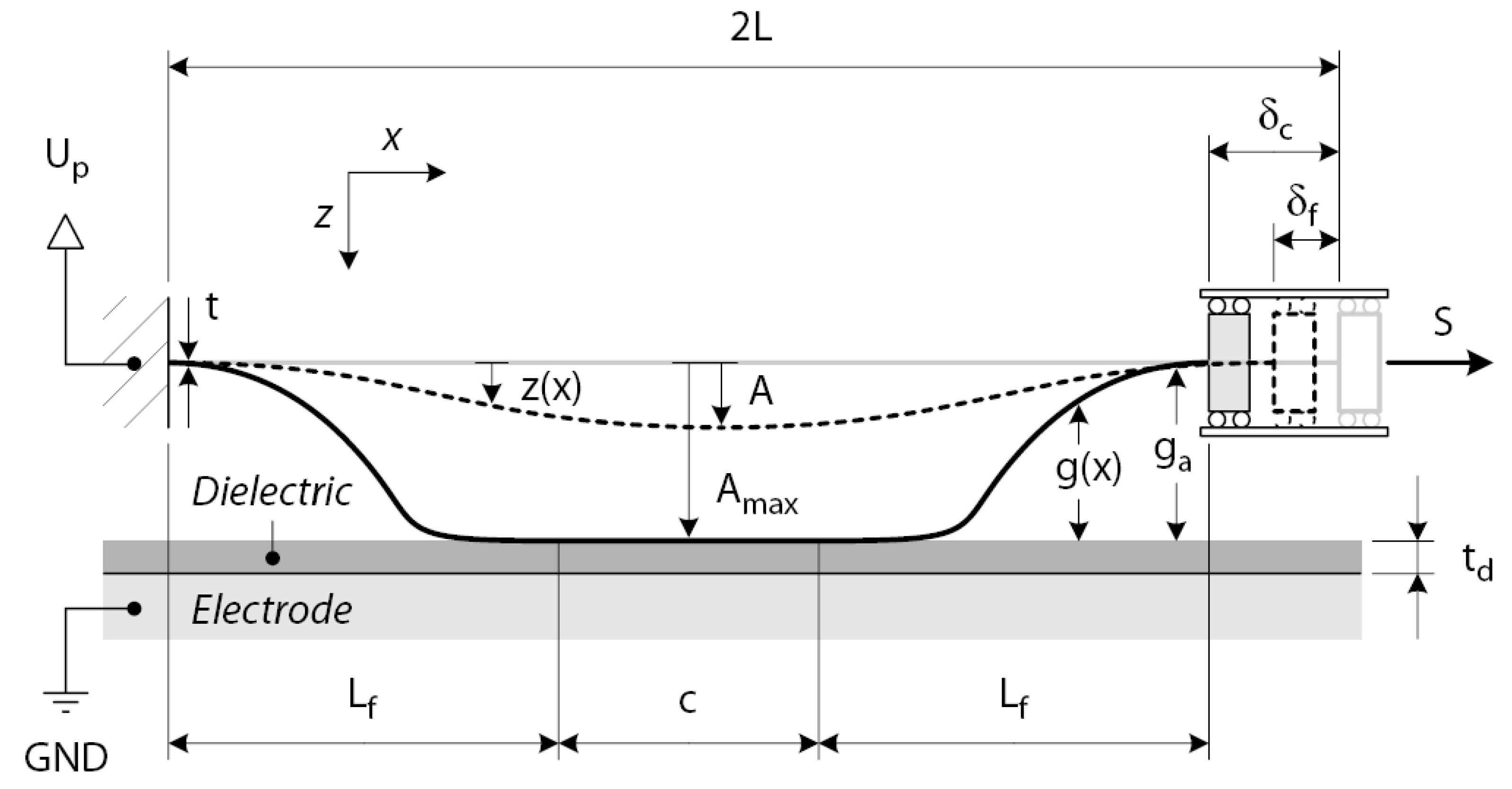
The shuffle motor converts normal inflexion of an electrostatically actuated plate into an in-plane step. To evaluate the step size, we consider an elastic plate with length
2L, thickness
t and width
w, as shown in
Figure 5. The plate is suspended at a distance
ga above the bottom electrode, which is covered with an insulating layer of thickness
td. The step size depends on the degree of the plate inflexion, which is directly related to the voltage
Up applied to the plate. Fine- and coarse-stepping motion can be attained by an appropriate choice of the actuation voltage. In the fine-stepping mode, the plate is operated in the stable regime below the pull-in voltage
Upi (
Up <
Upi). In this operational mode, the mechanical restoring force of the plate counteracts the electrostatic force, resulting in a relatively small normal inflexion of the plate and a fine longitudinal displacement
δf. In the coarse-stepping mode, the actuation voltage is set above pull-in (
Up ≥
Upi). In this case, the electrostatic attractive force between the plate and the substrate increases more rapidly with decreasing gap than the restoring mechanical force of the plate, causing instability and the ultimate collapse of the plate onto the substrate. The large deformation of the plate associated with this collapse results in a relatively large longitudinal displacement
δc.
Figure 5.
Schematic diagram showing the parameters used to model the plate deformation.
Figure 5.
Schematic diagram showing the parameters used to model the plate deformation.
4.1. Fine-stepping mode
When a voltage
Up is applied on the plate, an electrostatic force inflects the plate towards the grounded substrate. This induces a longitudinal contraction of the plate, moving the axially unrestrained end of the plate closer to the fixed end. To estimate the longitudinal contraction
δf, we consider a plate of length
2 L. From elastic bending theory, its longitudinal displacement
δf, also called the curvature shortening, can be approximated by [
23]:
where
z(
x) is the inflexion curve of the plate. The inflexion curve of half of the plate is approximated with the function:
where
A is the center inflexion of the plate. The shape function
z(
x) satisfies the boundary conditions (
z(0) =
z'(0) =
z'(
L) = 0 and
z(
L) =
A), giving a reasonable approximation of the real inflexion profile. The longitudinal displacement
δf of the movable end of the plate, operated below the pull-in voltage, is obtained by substituting the assumed inflexion profile into (1):
This result is in good agreement with the one derived by [
7].
The maximum inflexion of the plate at the midpoint before the pull-in instability is assumed to be 40% of the effective gap
geff [
24] defined as:
where
εr is the relative permittivity of the insulating layer.
4.2. Coarse-stepping mode
In the coarse-stepping mode, the plate is actuated above the pull-in voltage
Upi. The pull-in voltage is a function of the geometry of the plate and depends on the axial load
S. For zero axial load, the pull-in voltage of the plate is given by [
7]:
where
E is the plate's Young modulus and
ε0 is the permittivity of air. When the actuation voltage equals or exceeds the pull-in voltage
Up ≥
Upi, the plate makes physical contact with the grounded substrate, producing a relatively large longitudinal displacement,
δc >>
δf. The displacement
δc corresponds to that induced by a plate of length
2Lf with a center inflexion of
Amax:
Amax is determined by the initial gap
ga between the plate and the substrate minus the height of bumps (
Amax =
ga −
b). The length
2Lf is the part of the plate that is not in contact with the substrate and depends on the applied voltage
Up. By increasing the plate voltage, the contact region
c increases, decreasing the free length. To determine the free length of the plate, we consider the inflected part of length
Lf , as illustrated in
Figure 5. The electrostatic force
Fe working on this part is given by:
The mechanical restoring force
Fm of the inflected part can be approximated as the force required to inflect a cantilever plate of length
Lf with the guided-end boundary condition at distance
Amax:
The free length as a function of the applied voltage can be calculated by equating the electrostatic force and the mechanical restoring force (Fe = Fm). It follows from (6) and (7) that the free length is independent of the original length 2L of the plate. This implies that shuffle motors with different plate lengths will have the same step size for actuation voltages exceeding the pull-in voltage.
4.3. Output force
The shuffle motor employs inflexion and relaxation of the elastic plate for pulling and pushing the non-activated clamp, as illustrated in
Figure 1. When a tensile load
S is applied to the clamp, an axial strain is induced in the plate, reducing the clamp displacement correspondingly. If the axial strain equals the inflexion-induced shortening
δ, the net displacement of the clamp will be zero. The axial force associated with this strain is the maximum force that can be pulled by the shuffle motor:
Relaxation of the plate pushes the non-activated clamp. A compressive load
S greater than or equal to the buckling force of the plate will prevent stretching. The buckling load of the plate is thus the maximum load a shuffle motor can push. The buckling load of a rectangular plate clamped on the both ends is given by [
23]:
Depending on the geometry of the plate, the maximum output force of the shuffle motor will be limited either by the pulling or by the pushing force.
In order to transmit the force produced by the plate, a sufficient clamp force is required. The normal force
Fn is generated by applying a voltage difference
Uc between the clamp and the grounded substrate:
where
Ac is the clamping area. The normal force induces a frictional force
Ft in the clamp, whose magnitude depends on the coefficient of friction,
μ (
Ft =
μFn). In order to prevent slipping of the clamps, the frictional force must be larger than the maximum output force of the motor. The coefficient of static friction between silicon nitride/silicon nitride contacts is between 0.55 and 0.85 [
25]. Performance characteristics of the shuffle motors as predicted by the derived analytical models are summarized in
Table 2. For these calculations, we have used the dimensions listed in
Table 1. Furthermore we have used
E = 160 GPa as the Young’s modulus of polysilicon,
μ = 0.55 for the coefficient of friction,
ε0 = 8.85 × 10
12 C
2·N
−1·m
−2 for the permittivity of air and
εr = 7.5 for the relative permittivity of silicon nitride.
Table 2.
Calculated performances of the shuffle motors.
Table 2.
Calculated performances of the shuffle motors.
| | | Shuffle motor |
|---|
| Parameter | Symbol | Type I | Type II | Type III |
|---|
| Pull-in voltage (V) | Upi | 42.2 | 31.6 | 24.5 |
| Fine stepping (nm) | δf | 7.0 | 6.0 | 5.3 |
| Coarse stepping Upi ≤ Up≤ Up (nm) | δc | 48 ÷ 62 | 42 ÷ 62 | 37 ÷ 62 |
| Maximum pull force (mN) | Fpull | 4.8 | 4.2 | 3.7 |
| Maximum push force (mN) | Fpush | 2.3 | 1.7 | 1.3 |
| Clamp force 15 V ≤ Uc ≤ 60 V (mN) | Fn | 0.7 ÷ 10.8 | 0.7 ÷ 11.3 | 0.7 ÷ 11.9 |
| Frictional force 15 V ≤ Uc ≤ 60 V (mN) | Ft | 0.4 ÷ 5.9 | 0.4 ÷ 6.2 | 0.4 ÷ 6.5 |
5. Measurements
In this section, we report on measurements of speed, step size and output force performed on the fabricated shuffle motors. Unless otherwise noted, the measurement results apply to ‘Type I’ motors.
5.1. Stepping motion
We have successfully generated stepping motion with the shuffle motors using a coordinated sequence of clamps and plate voltages, as shown in
Figure 4(d),(e). The voltage sequence was generated using a multichannel analog output card and a high speed voltage amplifier. After each operation cycle, the polarity of the actuation voltage was reversed in order to reduce charge accumulation in the insulating silicon nitride layer.
The positioning performance of the motors was measured using an image processing technique based on the Fast Fourier Transform (FFT) [
26]. In this technique, the in plane motion of periodic patterns is recorded using a static video camera mounted on an optical microscope. The video showing the movement of the periodic patterns is then analyzed frame by frame in Matlab
® using the FFT method. The phase differences between the video frames are used to determine the displacement of the periodic patterns. This measurement technique enables sub-pixel displacement measurements with a resolution of a few nanometers [
27]. We have performed these measurements using the periodic patterns integrated on the shuffle motor (see
Figure 4(a),(d),(e)).
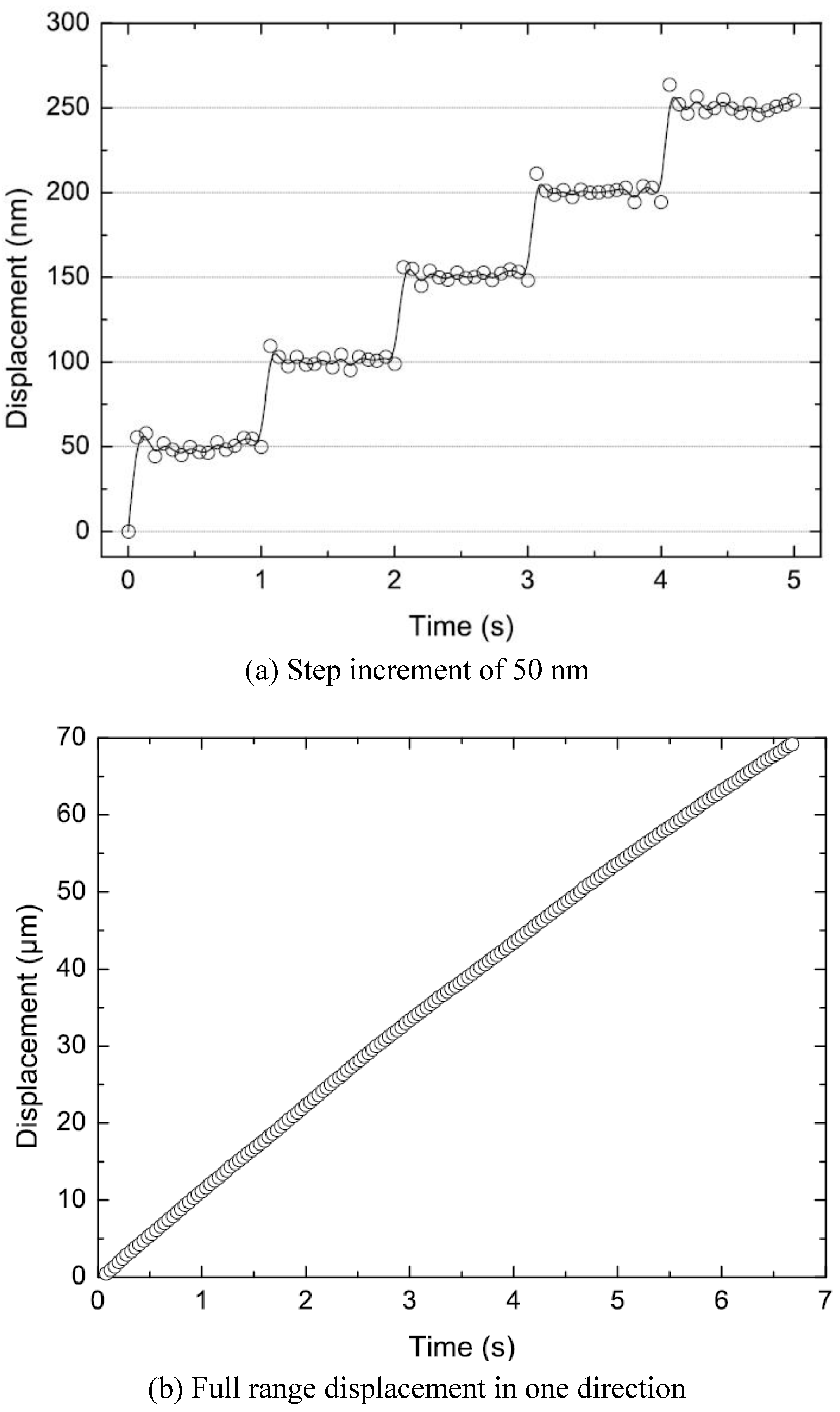
Figure 6 shows typical measurements of the motor position as a function of time. In
Figure 6(a), the motor was actuated at a cycling frequency of 1 Hz and a driving voltage of 45 V for both the clamps and plate. Due to the high resolution of these measurements, the individual steps can be clearly resolved. The step size was found to be 50 nm, which is in good agreement with the theoretical prediction (see
Table 2). The maximum displacement range of the motor was limited to ±70 μm by the suspension design. To achieve this relatively large stroke, we have used a motor suspended by a rather compliant crab-like suspension.
Figure 6(b) shows the motor displacement
versus time spanning the entire displacement range in a single direction.
Figure 6.
Measured displacement of a ‘Type I’ shuffle motor as a function of time. (a) Data were taken at a stepping frequency of 1 Hz and a driving voltage of 45 V for both the clamps and plate; (b) Data were taken at a stepping frequency of 200 Hz and voltages of 30 V and 50 V for the clamps and plate, respectively. The measurements are for one direction only. The displacement range is double.
5.2. Speed
The speed of the motor was determined by measuring the distance traveled for a given driving frequency and a fixed number of steps (typically 100 steps) [
10]. For each frequency, we took the average value of three measurements. The average deviation for each measurement point was lower than 0.1%.
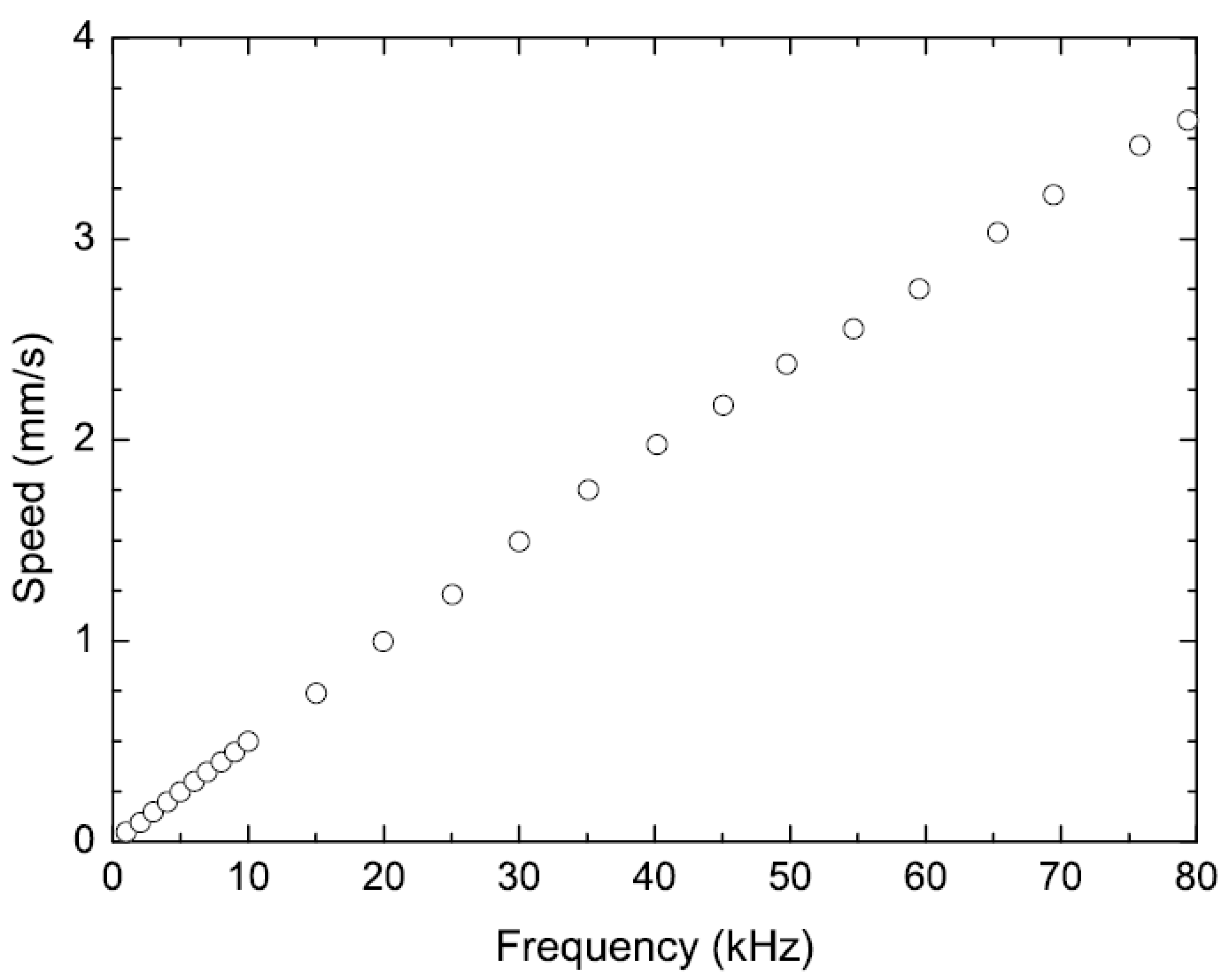
Figure 7 shows the speed of the shuffle motor as a function of the stepping frequency. The data were taken at frequencies up to 80 kHz with both clamps and plate driven at 45 V. The maximum frequency range of 80 kHz was limited by the driving electronics. These data show that the velocity increases nearly linearly with the cycling frequency over the measured range, with a maximum velocity of 3.6 mm/s at 80 kHz. The slope of the speed curve gives a measure for the average step size, which is about 50 nm. Considering that the plate resonant frequency was calculated to be 300 kHz, a considerably larger cycling frequency and speed is expected by improving the driving electronics.
Figure 7.
Measured speed of a ‘Type I’ shuffle motor versus the stepping frequency with clamps and plate driven at 45 V.
Figure 7.
Measured speed of a ‘Type I’ shuffle motor versus the stepping frequency with clamps and plate driven at 45 V.
5.3. Step size
The velocity of the shuffle motor depends on the cycling frequency and on the average step size. As discussed in
Section 4.1 and
Section 4.2, the step size of the motor is a function of the degree of plate deformation, which is directly related to the plate actuation voltage. As shown in
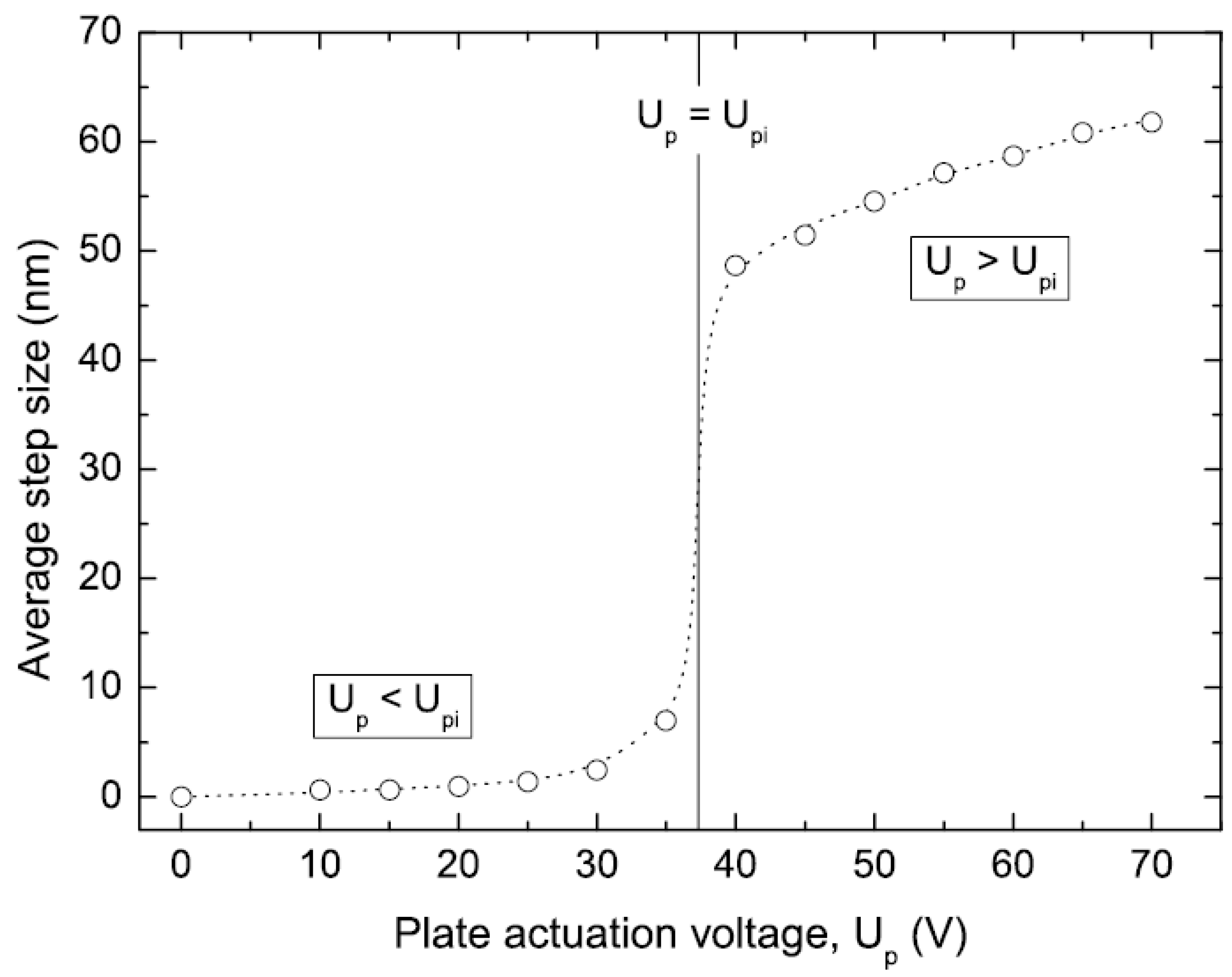
Figure 8, the two operational modes and the pull-in instability can be clearly identified. These measurements were performed at a cycling frequency of 200 Hz and a clamping voltage of 30 V. The pull-in voltage is found to be ~39 V, which agrees reasonably with the calculated 42.2 V (see
Table 2). We have observed an average step size from 0.6–7.0 nm for the motor operated below the pull-in voltage. Operation of the plate above the pull-in instability causes the plate to collapse on the substrate, resulting in a large plate deformation and a significant increase in step size. In the coarse-stepping operational mode, we have measured adjustable nanometer resolution steps ranging between 49 nm and 62 nm, corresponding to plate voltages varying between 40 V and 70 V. The measured step size for both non-contact and contact operational modes are in fair agreement with the theoretical predictions listed in
Table 2.
Figure 8.
Measured average step size of a ‘Type I’ shuffle motor versus the plate actuation voltage. A cycling frequency of 200 Hz and a clamp voltage of 30 V were used for these measurements.
Figure 8.
Measured average step size of a ‘Type I’ shuffle motor versus the plate actuation voltage. A cycling frequency of 200 Hz and a clamp voltage of 30 V were used for these measurements.
The measurements of the average step size for the three types of shuffle motors operated above pull-in are shown in
Figure 9 and compared with the analytical curve. The measured step size is in good agreement with the theoretical prediction and does not depend on the length of the plate, as expected from the model (see
Section 4.2).
As shown in
Figure 10, the step size of a shuffle motor is a function of the load applied to the clamps. To investigate this dependence, we have suspended the motor with connection springs on both clamps, as schematically illustrated in the inset of
Figure 10, and we have measured the motor’s displacement as a function of time at a fixed cycling frequency. From these data, we have extracted the step size as a function of the displacement and related it to the mechanical restoring force applied by the connection springs. When the motor walked against the springs in the forward motion, the step size decreased from 53 nm at zero load to 9 nm at 1.5 mN load. Conversely, when the motor traveled backward, the spring force assisted the motion, increasing the step size to 88 nm at a load of 1.5 mN.
Figure 10 shows that the step size varies linearly with the applied load.
Figure 9.
Average step size of the fabricated shuffle motors, operated above the pull-in instability. A cycling frequency of 200 Hz and a clamp voltage of 30 V were used for these measurements.
Figure 9.
Average step size of the fabricated shuffle motors, operated above the pull-in instability. A cycling frequency of 200 Hz and a clamp voltage of 30 V were used for these measurements.
Figure 10.
Measured step size of a ‘Type I’ shuffle motor versus the load on the clamps. The data were taken at a cycling frequency of 200 Hz with clamps and plate voltages of 55 V.
Figure 10.
Measured step size of a ‘Type I’ shuffle motor versus the load on the clamps. The data were taken at a cycling frequency of 200 Hz with clamps and plate voltages of 55 V.
5.4. Output force
To determine the output force of the motors as a function of the driving voltage, we have measured the maximum displacement range while varying the voltages on the clamps and plate. The output force was deduced from the displacement measurement and from the calculated stiffness of the suspension. Stiff suspensions were employed to enable force measurements over a wide range of output forces. The shuffle motors used for these measurements were suspended by fixed-guided beam flexures attached on both clamps, such as the one visible in
Figure 4(a). The stiffness of the beam elements is non-linear for large displacements due to the stress stiffening effect [
24]. The stiffness-deflection function was calculated by finite element method using ANSYS software. Since the motors worked against half of the connection springs at any given time (
i.e., the activated clamp balanced the force of the connection springs attached to it), only one half of the total suspension stiffness was used in the calculation. Either in the pull or in the push mode, the spring force can limit the maximum displacement of the motor. In the pull mode, the displacement is stopped when the tensile load on a non-activated clamp is sufficient to raise the pull-in voltage above the driving voltage. In the push mode, the maximum displacement is reached when the compressive load exceeds the plate buckling force. The measurements were performed on all of the three types of shuffle motors, using clamp voltages varying from 15 V to 60 V. The motors were operated above the pull-in instability.
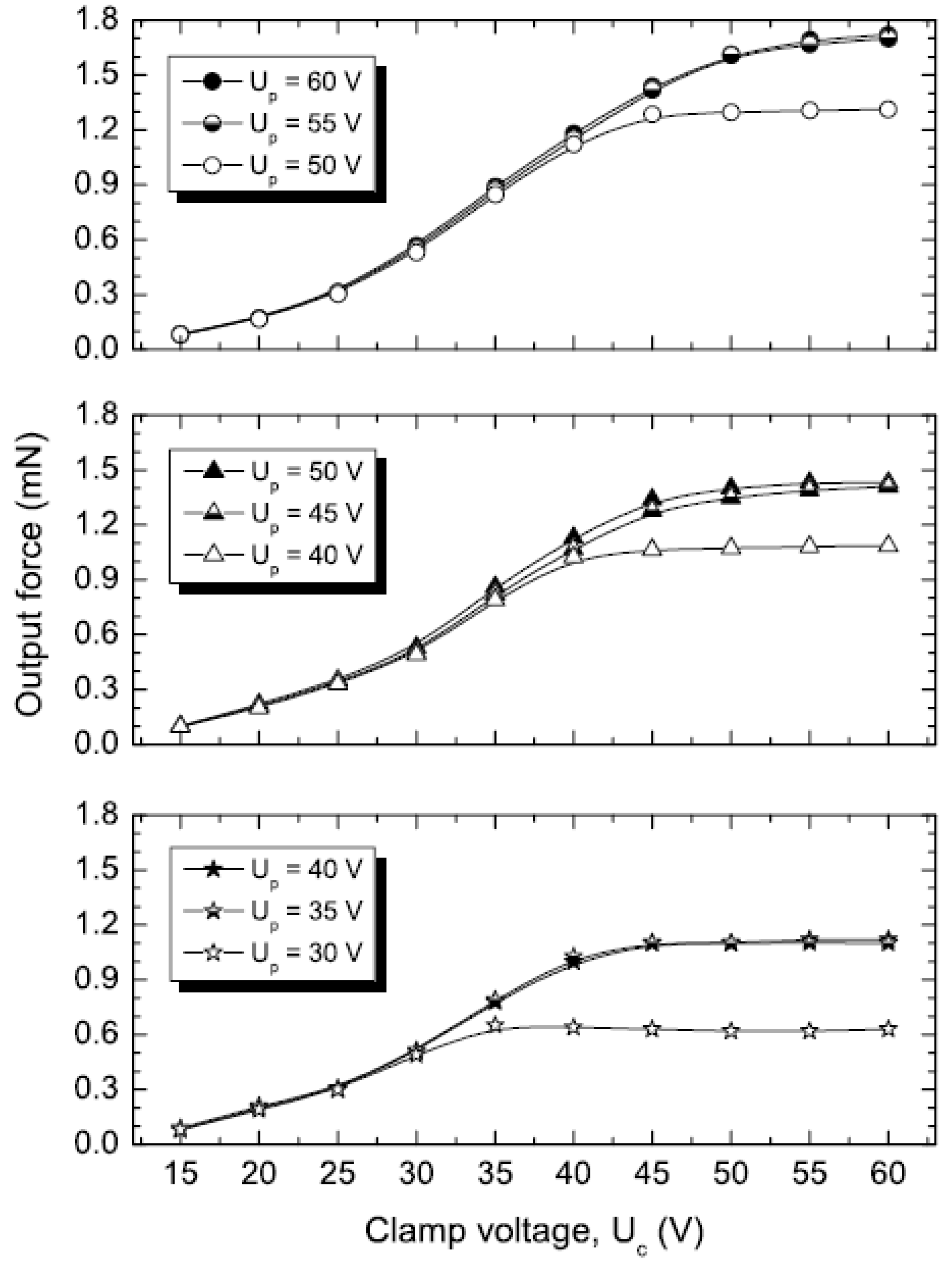
Figure 11 shows the output force as a function of the clamp voltage for the three types of shuffle motors, operated at different plate voltages.
Figure 11.
Measured output force of the shuffle motors
versus the load on the clamps. The symbols ●, ▲ and
![Micromachines 01 00048 i001]()
refer to the shuffle motors I, II and III, respectively (see legend in
Figure 9). The data were taken at a cycling frequency of 200 Hz.
Figure 11.
Measured output force of the shuffle motors
versus the load on the clamps. The symbols ●, ▲ and
![Micromachines 01 00048 i001]()
refer to the shuffle motors I, II and III, respectively (see legend in
Figure 9). The data were taken at a cycling frequency of 200 Hz.
The output force characteristics are qualitatively similar for the three types of motors. At lower plate voltages, the tensile load induced by the suspension limits the output force of the motor. The tensile load on a non-activated clamp, which increases monotonically with the displacement of the motor, raises the pull-in voltage of the plate. At a given displacement, the tensile load becomes sufficiently high enough to raise the pull-in voltage above the driving voltage, preventing further motion of the motor. This is visible through the different plateaus in the curves. By increasing the plate voltage, the output force increases until it saturates at another maximum value, which is given by the buckling force of the plate.
The maximum output force of ‘Type III’ motor is 1.1 mN (
![Micromachines 01 00048 i001]()
symbols in
Figure 11), which is in fair agreement with the theoretical value of 1.3 mN estimated for
Fpush (see
Table 2). Using (10) for the buckling force in combination with the measured output force (
FIII) and the length of the plate (
LIII) of ‘Type III’ motor, the output force (
FII) of ‘Type II’ motor can be accurately predicted:
This prediction is in good agreement with the measured force of 1.4 mN, as shown in
Figure 11 (▲ symbols). The same calculation for ‘Type I’ motor with a plate length of 180 μm predicts a maximum output force of 1.9 mN, which is close to the measured force of 1.7 mN, as shown in
Figure 11 (● symbols).
These results are in fair agreement with the model developed in
Section 4.3. Indeed, the maximum output force of the shuffle motor is determined by the lower of the pulling or the pushing force. Hence, in our design, the output force is in all cases limited by the pushing force. Considering this, the measured output forces are lower than the estimated values for
Fpush. The small discrepancy can be attributed to the fact that the plates are actually perforated; that is, the buckling forces of the plates are lowered due to the presence of bumps.
The maximum output force of 1.7 mN demonstrated for ‘Type I’ shuffle motor was achieved with actuation voltages of 55 V on both clamps and plate. This corresponds to a force density of 4.78 N·m
−2·V
−2 and a power density of 1.7 × 10
−2 W·m
−2·V
−2, which are the highest values reported so far for electrostatic microactuators (see
Figure 1 and
Table A1).
5.5. Lifetime
A limited lifetime test was conducted to determine the durability of the shuffle motor. The motor was run continuously for five days at a cycling frequency of 80 kHz, generating nearly 34 billion steps, equivalent to a displacement of 1.5 km. This did not result in any noticeable change in performance.


 refer to the shuffle motors I, II and III, respectively (see legend in Figure 9). The data were taken at a cycling frequency of 200 Hz.
