An Electromagnetically-Actuated All-PDMS Valveless Micropump for Drug Delivery

Abstract
: This paper presents the fabrication process of a single-chamber planar valveless micropump driven by an external electromagnetic actuator. This micropump features a pair of micro diffuser and nozzle elements used to rectify the fluid flow, and an elastic magnetic membrane used to regulate the pressure in the enclosed fluid chamber. Polydimethylsiloxane (PDMS) is used as the main construction material of this proposed micropump, including the structural substrate and the planar actuation membrane embedded with a thin micro magnet. Both the Finite Element Method and experimental analysis are used to assess the PDMS-membrane actuation under the applied electromagnetic forces and characterize the pump performance at variable working conditions. The resonant frequency of this micropump is identified experimentally and de-ionized (DI) water is loaded to account for the coupling effects of the working fluid. The experimental data was used to demonstrate the reliability of flow rates and how it can be controlled by consistently adjusting the driving frequencies and currents. The proposed micropump is capable of delivering a maximum flow rate of 319.6 μL/min and a maximum hydrostatic backpressure of 950 Pa (9.5 cm H2O). The planar design feature of the pump allows for potential integration of the pump with other PDMS-based microfluidic systems for biomedical applications.1. Introduction
Micropumps play a crucial role in future drug delivery, such as the delivery of insulin, hormonal and pain management drugs [1]. The main drive or actuation of a micropump provides these devices with the means to control and dispense small amounts of fluids to a required target area. Therefore, the micropump becomes an essential component of microfluidic transport systems, with a potential to impact a broad area of research. The advantages of micropumps in general are their small dimensions, accurate flow rate control, low power consumption, and high compatibility with other microfluidic systems. Basically, micropumps can be classified into two categories [2,3] mechanical and non-mechanical, which is based on the principle of converting external mechanical energy or non-mechanical energy directly into kinetic energy. Mechanical micropumps rely on the pressure changes generated by external actuators, whereas the non-mechanical micropumps directly move the molecules or ions in the fluid. Although easily implemented, either from a fabrication or an operation point of view, the performance of the non-mechanical micropump is highly dependent upon the properties of the pumping fluids (permittivity, conductivity and pH, etc.).
Micropumps have been the subject of a number of research projects since the early years of Microelectromechanical system (MEMS) development. The first silicon-made mechanical micropump was introduced in the 1980s and was based on a piezoelectric actuation mechanism with the intention of being used in controlled insulin delivery systems [4]. This work demonstrated the feasibility of silicon-based micropump and inspired extensive research on micropumps [2,5]. Nevertheless, the complicated silicon micromachining and high-cost of the pump fabrication as well as the requirement of high voltages limit their applications in the biomedical field.
The current research trend is leaning towards the development of micropumps by enhancing their performance and miniaturization, keeping the cost low. Recently, new polymeric materials like Poly-methyl methacrylate (PMMA), Poly-olefines (COC, COP), Polydimethylsiloxane (PDMS), and polyimide have been widely employed as substrate or actuation membranes [6,7] for their ease of handling and low cost. Also, new fabrication techniques such as soft lithography, hot embossing, and injection molding as well as laser ablation, are being pursued. Some actuation mechanisms, especially in the non-mechanical micropumps, such as surface acoustic streaming [8], bubble expansion [9] and laser beam radiation [10] etc., have been used for different ranges of volumetric dosing from hundreds of nanoliters/min to a few microliters/min. The reliability and integration of micropumps is a serious, important concern due to their applications in biomedical fields and life sciences. For example, they are used in the disposable micro Total Analysis Systems (μTAS) for chemical and biological analysis, and implantable drug delivery systems for fine regulation of medication [11].
Current micropumps [2] employ a variety of actuation mechanisms and fluid control valves which involve complex structure designs and fabrication of a multiple layer alignment and assembly. Therefore, the objective of this design is to create an easily fabricated, less expensive, and finer controlled micropump for the accurate volumetric dosing of therapeutic agents. In this study, a planar valveless micropump, which is driven by an external electromagnetic actuator and is able to generate a large volume stroke, was developed. The soft polymer, polydimethylsiloxane (PDMS) is used as both the functional membrane and the structural substrate of the micropump due to its excellent biocompatibility, good mechanical properties and simple fabrication process. A thin micro magnet (0.5 mm in thickness) is embedded into a PDMS membrane to form a planar actuation membrane, instead of the bossed structure such as the one reported by [12,13]. In this design, the electromagnetic force is applied through the membrane to drive the fluid flow. Compared to other micropumps, the presented planar micropump is compact and has no wire connection to the chip, which allows for ease of integration and fast prototyping. The fabrication method proposed provides a simple but effective solution for laboratory testing.
2. Working Principle and Fabrication
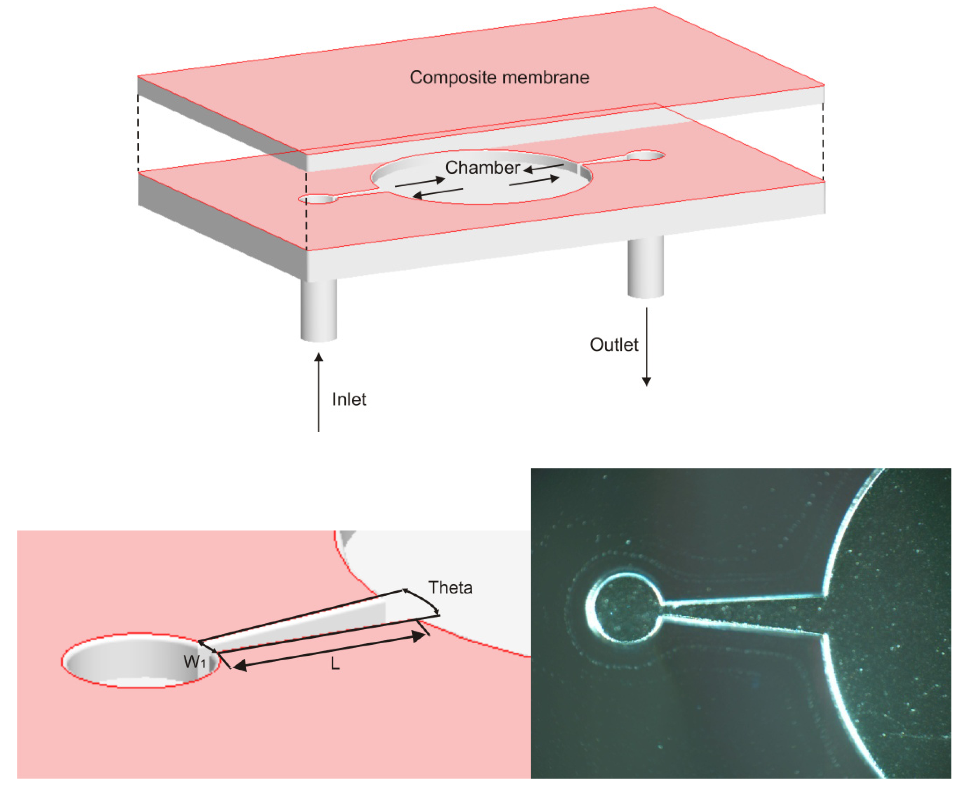
This valveless micropump consists of two layers: (1) a substrate layer that is patterned with micro channels, a flow directing component and a fluid chamber; (2) an actuation membrane which is directly integrated with a permanent micro magnet and serves as a control layer. The polarities of the miniature magnet render the polarities of the membrane, thus allowing the membrane to be bi-directionally driven from its relaxed state. Finally, these two layers are bonded to form a closed microfluidic pathway. The schematic of the micropump is shown in Figure 1. Diffuser and nozzle elements were used in this micropump because of their simple and planar characteristics, which help to avoid the introduction of additional mechanical components into the pump.
2.1. PDMS Actuation Membrane
The actuation force is applied through the composite membrane to drive the working medium in the pump. Thus, the reliability and performance of the micropump rely heavily on the material properties and thickness of the membrane. For example, a thick membrane suffers the disadvantage of limited deflection under magnetic forces, whereas a thin membrane embedded with a bulk micro magnet is easily broken when released from the mold during the fabrication process.
PDMS Silgard184 (Dow Corning Corp) was used in this study. First, a PDMS pre-polymer (at 10:1 weight ratio) was thoroughly mixed after being degassed in a vacuum chamber. Then, a thin 150 μm PDMS membrane was spin-coated on a 3 inch silicon wafer, with a thickness of 375 μm, at a speed of 700 rpm for 10 s and then cured at 75 °C for two hours on a hot plate. A magnet (NdFeB), (with dimension of 3 × 3 × 0.5 mm3, a weight of 0.03 g and a magnetized direction through thickness) was placed in the middle of the first PDMS layer and again, the liquid pre-polymer was poured around the magnet to form a second layer. Then, a glass slide was used to remove the extra mixture. The silicon wafer together with the PDMS and magnet was put on the hot plate for 30 min at 100 °C. Using the same method, another 150 μm PDMS was covered to encapsulate the magnet. Finally, the whole PDMS membrane was peeled from the silicon wafer and cut to the required size to match the substrate layer.
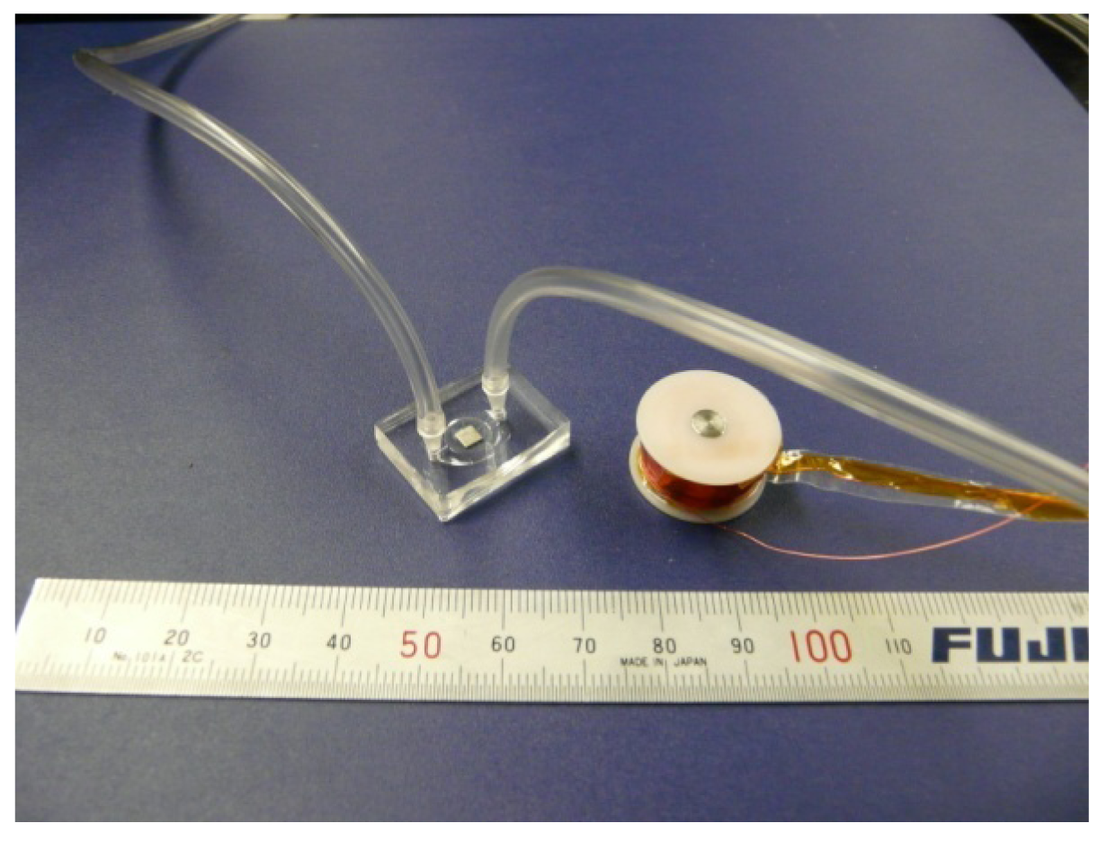
The curing agent ratio (5:1) in the PDMS re-polymer was changed in order to increase the rigidity of the fluid chamber (diameter of 7 mm, depth of 450 μm). The liquid PDMS mixture was poured onto the SU-8 mold to obtain the desired microstructures, which consists of a fluid chamber and input/output flow channels (W1 = 100 μm, L = 1.6 mm, θ = 10°), shown in Figure 1. After punching out the inlet and outlet for the tubing connection, the rigid substrate layer and flexible membrane layer were placed into an oxygen plasma chamber (10% oxygen, 150 W). Finally, the two layers were carefully aligned and pressed together. The final outer dimension of the micropump body is 20 × 12 × 3.5 mm3 shown in Figure 2.
3. Experimental Setups
3.1. Measurement of Electromagnetic Forces
An external electromagnet actuator is also shown in Figure 2. It consists of an electromagnetically inductive coil wound around a soft iron cylindrical rod (Φ5 mm); and the resistance and inductance of copper coils (AWG32, 920 turns) is about 40.7 Ω and 30.07 mH under 100 Hz conditions. Varying electromagnetic field is generated and controlled through an excitation circuit. Thus, alternating attractive or repulsive forces can periodically deflect the elastic actuation membrane when the electromagnetic field is reversed. The vertical electromagnetic force Fz acting on the membrane through the bulk micro magnet is given by [14]:
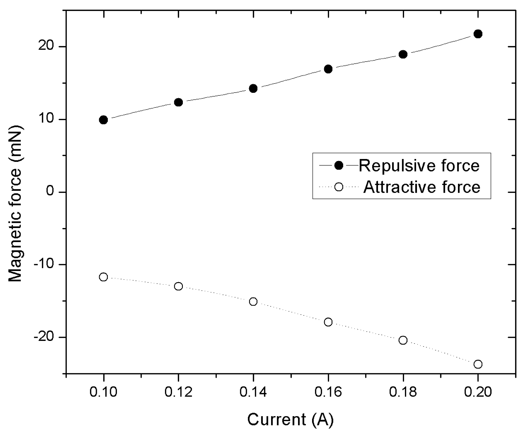
Using a simple method, the static electromagnetic forces on the micropump—under currents of 0.1 A to 0.2 A—were roughly measured. The micropump was fixed on a digital scale and its weight was set to zero. Then, the electromagnet was fixed on the top of the micro magnet with an initial gap of 1mm. The vertical position can be adjusted through a clamp and a linear stage. The maximum readings of the digital scale at different currents were recorded. Thus, the reading from the digital scale can be considered as the electromagnetic force on the micropump during the operation; the relationship between the deflections of the actuation PDMS membrane and the applied currents can then be obtained. The maximum attractive and repulsive forces on the membrane measured were about 23.7 mN and 21.7 mN, respectively, under a current of 0.2 A
In Figure 3, it was observed that the attractive forces were larger than the repulsive forces because the resultant attractive forces pulled the membrane towards the electromagnet and thus decreased the air gap. The deflection of the membrane changed the air gap and, in return, affected the electromagnetic field. For instance, electromagnetic forces pulled the membrane and thus decreased the air gap. The membrane did not stop moving until a balance was reached between the electromagnetic force and the elastic force of the PDMS membrane. Therefore, the maximum deflection was achieved.
3.2. Estimation of PDMS Deformation and Stress Distribution
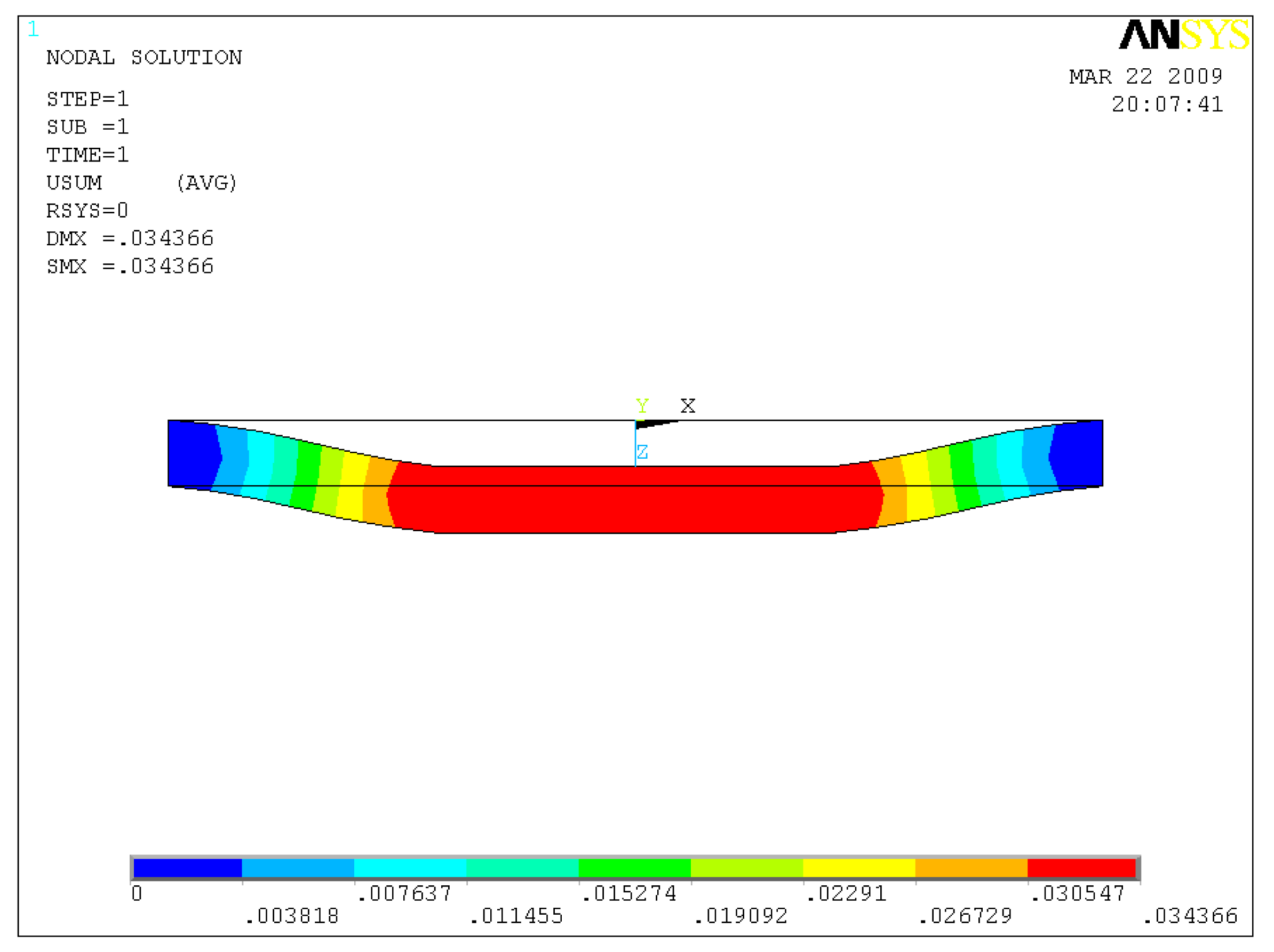
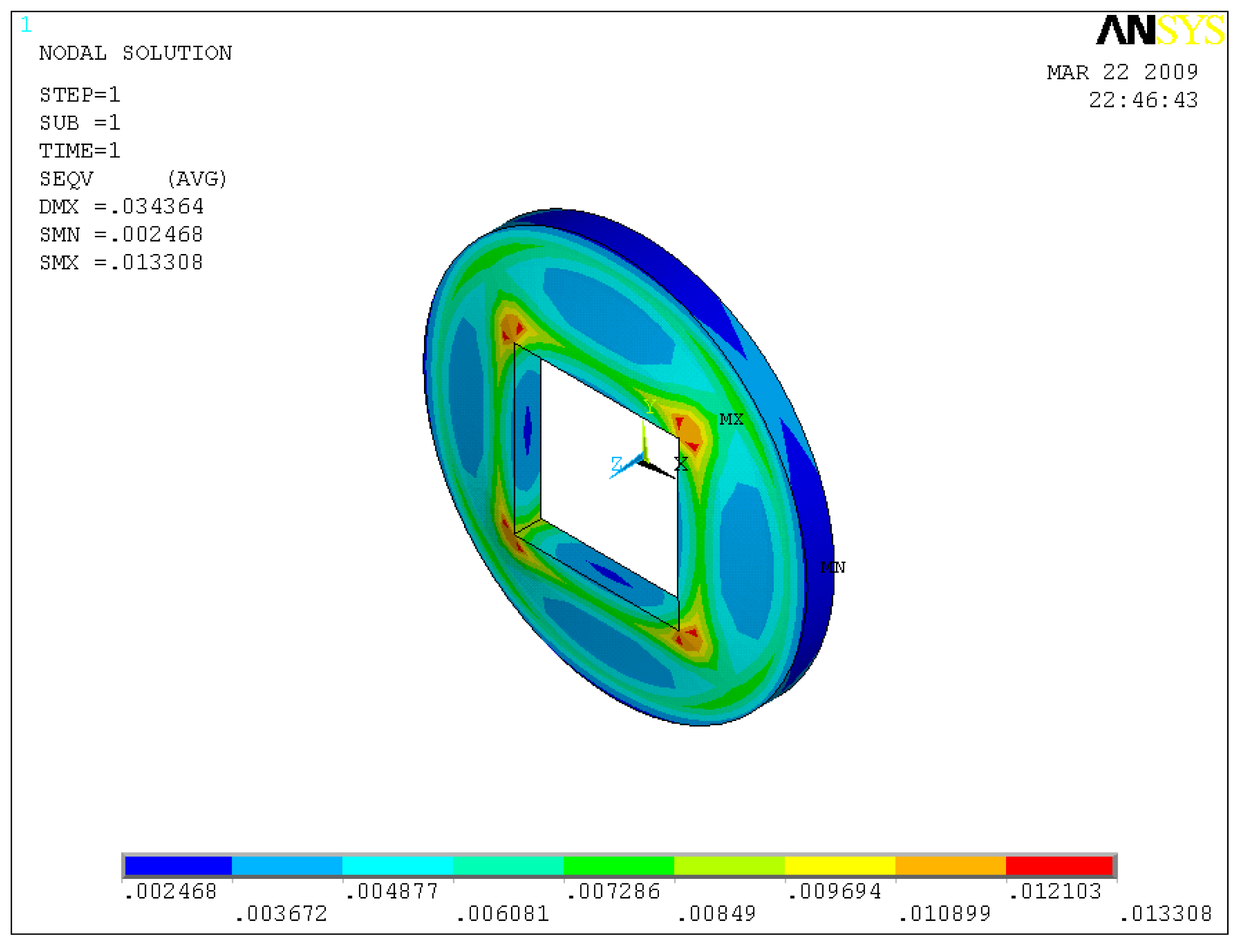
Conventional membrane deformation measurement methods, such as a laser displacement sensor and a high-speed video camera, have been reported in previous micropump studies [15]. In this work, however, the force measurement results in Section 3.1 and the numerical calculations were combined to roughly estimate the PDMS deformation and stress distribution. The maximum forces measured were used as the load conditions for numerical calculation. The end width (0.38 mm) of the micro channel is small compared to the diameter of the membrane, therefore the fixed edge boundary condition of the PDMS membrane is assumed in the simulation. The density and Young's modulus of the PDMS and NdFeB are 1.027 × 10⁻⁶ Kg/mm3and 6.667 × 10⁻⁶ Kg/mm3, 0.75 MPa and 151 MPa, respectively. The Poisson's ratios of the materials are 0.45 and 0.24, respectively.
As the simulation results show in Figure 4, the deflection distribution of the membrane has a trapezoidal shape and a maximum deflection of 34.34 μm is observed. It was found that the depth of the fluid chamber is higher than the maximum deflection, which ensures that the membrane will not contact the bottom of the fluid chamber. As de-ionized (DI) water is loaded in the pump chamber, the deformation of the elastic PDMS membrane is even less than the aforementioned deflection value due to fluid resistance. Since the difference of material properties of the bulk micro magnet and the PDMS layer exists, the magnetic force is concentrated on the area encapsulating the magnet. The maximum deflection area is on the bottom of the membrane. The stress distribution of the elastic membrane is shown in Figure 5. The maximum stresses of 0.1425 MPa, which were lower than the tensile of fracture strength (2.24 MPa) of PDMS material [16], are mainly distributed on the four corners of the bulk magnet due to its square shape. Thus, attention should be given to those areas. The static analysis of the membrane helps to estimate potential failure of the membrane, thereby ensuring the reliability of micropump operation.
4. Results and Discussion
4.1. Characterization of the Micropump
A micropump operating at resonant frequencies results in an increased displacement, large flow rates and high conversion efficiencies, thus reducing power requirements. Thus, it is very important to identify the resonant frequency of pump prototypes at different working conditions. The micropump prototype was tested at different currents and excitation frequencies. The characteristic parameters, such as maximum flow rates and maximum backpressure the pump can resist, were measured and plotted.
The schematic of the experiment setup for measuring flow rate and backpressure for the micropump prototypes is illustrated in Figure 6. Inlet and outlet tubing are the commercially available TYGON® tubing with an inner diameter of 1.6 mm and outer diameter of 3.2 mm. The inlet tubing is connected to a syringe as the fluid reservoir. DI water was used as a working fluid in this study. The physical properties of the working fluids are 20 °C and 1 atm (density: 0.997 g/mL, viscosity: 1.025 × 10⁻³ m2/s). When the fluid is moving forward, the syringe will automatically prime the fluid chamber.
The average volumetric flow rate (Equation (2)) was calculated from velocity of the fluid-air interface at the outlet tubing and the diameter of the tubing. Once the micropump was performing properly and the fluid was working stably, an average speed of the fluid moving along a certain distance in the tubing was measured by a stopwatch.
The initial air gap between the micro magnet and the electromagnet is about 1 mm and the backpressure between inlet and outlet maintains zero. The magnitudes of the current applied through the electromagnet are 0.1 A and 0.18 A, respectively.
As shown in Figure 7, it was found that the measured peak flow rate of the pump was about 319.6 μL/min at the frequency of 36.9 Hz for 0.18 A current, while the maximum flow rate of 196 μL/min was reached at the frequency of 33.6 Hz for 0.1 A current. There is 8.94% deviation between these two tests regarding the resonant frequency. The flow rate is proportional to the magnitude of the applied currents on the electromagnet if other working conditions are kept the same. The following experimental results are expected.
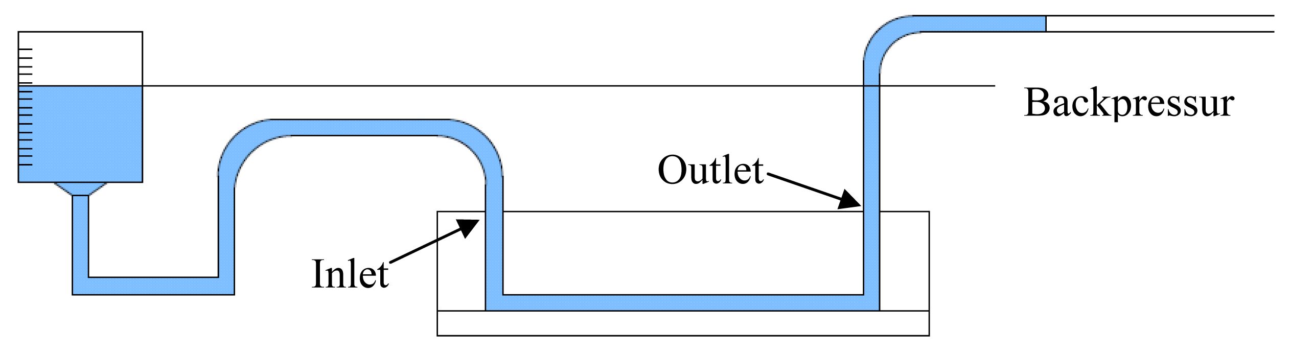
The maximum pressure deliverable by the micropump is determined through hydrostatic testing. As the micropump works for a certain time, the level of fluid in the reservoir will decrease, while the fluid level in the output tubing will increase. Thus, there is a static equilibrium between the pump and the weight of the column of fluid in the tubing. We therefore define the maximum backpressure as the opposing pressure exerted on the fluid when this equilibrium is reached and the flow rate of the micropump becomes zero.
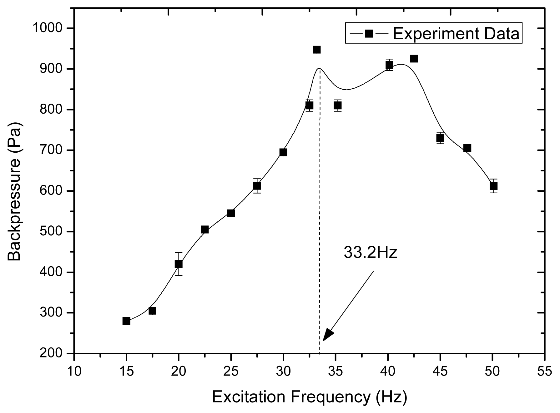
We measured the backpressures at different excitation frequencies from 15 Hz to 50 Hz at the magnitude of 0.18 A current, shown in Figure 8. DI water was used as the working fluid. The maximum backpressure was measured at about 950 Pa (9.5 cm H2O backpressure) at the excitation frequency of 33.2 Hz.
4.2. Bubble Effects on Pump Performance
Air bubbles trapped inside the micropump severely affect the pump performance and also make the conduction of characterization experiments difficult. It was observed that the air bubble in the middle of the fluid chamber acted as a mechanical spring expanding and compressing with the actuation of the elastic membrane. This resulted in a low pressure in the pump chamber, thus very low flow rates. If the air bubble was on the inlet channel, it would act like a ball valve, opening and closing the inlet channel alternatively, with the actuation of the PDMS membrane in supply and pump mode. The flow rates and backpressures were increased suddenly due to the prevention of reverse flow from the inlet channel by the air bubble. This phenomenon explains why the micropump with ball valves or check valves, can resist a relatively high backpressure, compared with the valveless pump. It was also observed that one small air bubble would stick on the outlet channel, the flow rate would be reduced and sometimes the fluid is oscillating around the initial level.
Therefore, it is important to remove air bubbles inside the chamber before characterization experiments. There are two ways to avoid air bubbles trapped inside the pump chamber on the performance. In this micropump prototype, the compression ratio (stroke volume and dead volume of the fluid chamber) is 6.8%. One design criteria for a bubble tolerant micropump is to increase the compression ratio [17]. Thus, reducing the dead volume of the fluid chamber enables the maximized prevention of gas bubble formation inside the pump and decreases the effect of bubbles on the pump performance. Also, submerging the pump into DI water in a large vacuumed chamber for a few minutes to one hour can be used to remove air inside the chamber.
4.3. Stability Issue of Micropump Operation
Achieving a constant continuous pumping is an important index of a reliable micropump. Reviewing the literature shows that silicon, glass and polymers are used as the main materials for constructing mechanical micropumps, including the pump body and actuation membrane. It was found that stiff actuation membranes are capable of operating at high resonant frequencies and resisting high backpressure, which makes the micropump work stably. On the other hand, for the low-modulus membranes, large stroke volume can be obtained. However, this type of pump works in a low excitation frequency range, which causes some stability problems, such as pulsate and discontinuous fluid flow. For this proposed PDMS micropump, it was found that the fluid in the outlet tubing was oscillating around the initial position and it was also found that the pump failed to transport the fluid as the excitation frequency was below 15 Hz. This is because the valveless micropump has low fluidic impedance in both directions and suffers reverse flow. Therefore, it is difficult to accumulate enough net fluid flow if the excitation frequency is too low. Furthermore, the fluid flow was pulsating when the frequency was between 15 Hz and 20 Hz; this resulted from the periodic nature of the electromagnetic field applied through the elastic PDMS membrane. As the frequency increased to above 15 Hz, this micropump worked quite stably and the transported fluid flow was continuous. Flow rates increased with excitation frequencies and reached a peak value at resonant frequency, and decreased subsequently. These results imply that the flow rate in this kind of micropump can increase linearly in a certain excitation frequency range and can be adjusted easily by the magnitude of the current.
5. Conclusion
In this study, we described the feasibility of fabricating an all-PDMS valveless micropump and its performance characterization with an externally separated electromagnet actuator. The merits of utilizing planar nozzle and diffuser elements include ease of fabrication and integration into other microfluidic devices, thereby miniaturizing the whole microfluidic system. The micropump is not sensitive to the density, ionic strength and particles in the working fluid, which shows great potential for drug delivery application.
The maximum flow rate of 319.6 μL/min and backpressure of 9.5 cm H2O was achieved at the excitation frequency of 36.9 Hz under a current of 0.18 A through the electromagnet. The characterization experiments reveal that the flow rates of this valveless micropump are proportional to the magnitude and certain range of the frequency of the driving currents. Therefore, linear output flows can be adjusted by the magnitude and excitation frequency of the driving currents. The currents can be lowered to reduce power consumption and prevent a temperature rise in the electromagnet. Future work will be focused on the optimization of the pump structure, such as improving the bubble tolerance ability and dual chamber design [18], as well as improving the amount backpressure that the micropump can resist.


References
- Evans, A.T.; Park, J.M.; Chiravuri, S.; Gianchandani, Y.B. A low power, microvalve regulated architecture for drug delivery systems. Biomed. Microdev. 2010, 12, 159–168. [Google Scholar]
- Amirouche, F.; Zhou, Y.; Johnson, T. Current micropump technologies and their biomedical applications. Microsyst. Technol. 2009, 15, 647–666. [Google Scholar]
- Nisar, A.; Afzulpurkara, N.; Mahaisavariyaa, B.; Tuantranont, A. MEMS-based micropumps in drug delivery and biomedical applications. Sens. Actuat. B Chem. 2008, 130, 917–942. [Google Scholar]
- Smits, J.G. Piezo-Electrical Micropump European Patent 19,840,201,185, 15 August 1984.
- Laser, D.; Santiago, J. A review of micropumps. J. Micromech. Microeng. 2004, 14, R35. [Google Scholar]
- Liu, C. Recent developments in polymer MEMS. Adv. Mater. 2007, 19, 3783–3790. [Google Scholar]
- Tsao, C.; Hromada, L.; Liu, J.; Kumar, P.; DeVoe, D.L. Low temperature bonding of PMMA and COC microfluidic substrates using UV/ozone surface treatment. Lab Chip 2007, 7, 499–505. [Google Scholar]
- Ogawa, J.; Kanno, I.; Kotera, H.; Wasa, K.; Suzuki, K. Development of liquid pumping devices using vibrating microchannel walls. Sens. Actuat. A Phys. 2009, 152, 211–218. [Google Scholar]
- Yin, Z.; Prosperetti, A. A microfluidic'blinking bubble'pump. J. Micromech. Microeng. 2005, 15, 643–651. [Google Scholar]
- Maruo, S.; Inoue, H. Optically driven micropump produced by three-dimensional two-photon microfabrication. Appl. Phys. Lett. 2006, 89, 144101. [Google Scholar]
- Shawgo, R.S.; Grayson, A.C.; Li, Y.; Cima, M.J. BioMEMS for drug delivery. Curr. Opin. Solid State Mater. Sci. 2002, 6, 329–334. [Google Scholar]
- Yamahata, C.; Lacharme, F.; Burri, Y.; Gijs, M. A ball valve micropump in glass fabricated by powder blasting. Sens. Actuat. B Chem. 2005, 110, 1–7. [Google Scholar]
- Pan, T.; McDonald, S.J.; Kai, E.M.; Ziaie, B. A magnetically driven PDMS micropump with ball check-valves. J. Micromech. Microeng. 2005, 15, 1021. [Google Scholar]
- Feustel, A.; Krusemark, O.; Müller, J. Numerical simulation and optimization of planar electromagnetic actuators. Sens. Actuat. A Phys. 1998, 70, 276–282. [Google Scholar]
- Jeong, O.C.; Park, S.W.; Yang, S.S.; Pak, J. Fabrication of a peristaltic PDMS micropump. Sens. Actuat. A Phys. 2005, 123, 453–458. [Google Scholar]
- Mark, J.E. Physical Properties of Polymer Handbook; Oxford University Press: New York, NY, USA, 1999; p. 431. [Google Scholar]
- Richter, M.; Linnemann, R.; Woias, P. Robust design of gas and liquid micropumps. Sens. Actuat. A Phys. 1998, 68, 480–486. [Google Scholar]
- Zhou, Y. Design and Microfabrication of an Electromagnetically-Actuated Soft-Polymer Micropump. Ph.D. Thesis, University of Illinois at Chicago, Chicago, IL, USA, 2010. [Google Scholar]
© 2011 by the authors; licensee MDPI, Basel, Switzerland. This article is an open access article distributed under the terms and conditions of the Creative Commons Attribution license (http://creativecommons.org/licenses/by/3.0/).
Share and Cite
Zhou, Y.; Amirouche, F. An Electromagnetically-Actuated All-PDMS Valveless Micropump for Drug Delivery. Micromachines 2011, 2, 345-355. https://doi.org/10.3390/mi2030345
Zhou Y, Amirouche F. An Electromagnetically-Actuated All-PDMS Valveless Micropump for Drug Delivery. Micromachines. 2011; 2(3):345-355. https://doi.org/10.3390/mi2030345
Chicago/Turabian StyleZhou, Yu, and Farid Amirouche. 2011. "An Electromagnetically-Actuated All-PDMS Valveless Micropump for Drug Delivery" Micromachines 2, no. 3: 345-355. https://doi.org/10.3390/mi2030345
APA StyleZhou, Y., & Amirouche, F. (2011). An Electromagnetically-Actuated All-PDMS Valveless Micropump for Drug Delivery. Micromachines, 2(3), 345-355. https://doi.org/10.3390/mi2030345