1. Introduction
Microfluidic devices are used on a daily basis for preparation and/or analysis of biological samples [
1,
2,
3]. To take full profit of the advantages coming from miniaturization, such as small sample volume, samples are injected through tiny channels. One of the biggest problems caused by this miniaturization is related to the presence of air bubbles inside the sample volume, which may lead to such issues as channel clogging, inaccuracy of sample volume, or dysfunction. The bubbles can be of various sizes, and be present accidently or on purpose, as for the sake of separating consecutive samples before analysis.
There exist some commercial solutions to remove those bubbles such as the Systec Debubbler series (BioTech AB, Sweden), but they all involve relatively large dead volumes (>1 mL) in comparison with the sample volumes used in microfluidics. Some micro-debubblers have been developed recently [
4,
5,
6], but they use bubble traps limiting the size of the bubbles that can be removed, and increasing the dead volume of the device. Other recent articles describe stand-alone microfluidic-based debubblers using hydrophobic membranes [
7,
8], as well as a debubbler using micromachined air vents [
9]. A simpler solution was mentioned in [
10], in which the authors described the use of porous tubing by Gore and Assoc. However that tubing, which is not available anymore, still had considerable dead volume (1 mm inner diameter).
This paper describes the fabrication and evaluation of two simple micro-debubbler embodiments featuring sub-microliter dead volume and which can remove bubbles of tens of microliters at flow rates of around 100 µL/min. The systems make use of a 2 mm thick Tracetrap porous polytetrafluoroethylene (PTFE) filter membrane plate of TRACE Analytics, Germany. This material is permeable to air but not to aqueous liquids up to 2 bar overpressure, and features pore sizes of 2.5 µm making it suitable for sterile environment. The injection of a sample including bubbles is performed at overpressure to allow the air to be removed thanks to its selective transport through the membrane.
2. Device Designs and Fabrication
2.1. Device Fabrication
The PTFE filter plate has been implemented in two setups. The first embodiment is somewhat similar to that of Xu
et al. [
7] as it also uses a hydrophobic membrane. However, the membrane plate is inserted without gluing on top of a microfluidic chip inside a modified chip holder, as shown in
Figure 1. The setup, which was previously described by Braschler
et al. [
11], consists of a chip assembly with a PDMS cover.
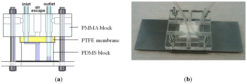
Figure 1.
Horizontal debubbler integrated in chip holder. (a) Sketch of assembly (chip not visible, at bottom); (b) Picture of the assembly; the filter plate is visible as a white square.
Figure 1.
Horizontal debubbler integrated in chip holder. (a) Sketch of assembly (chip not visible, at bottom); (b) Picture of the assembly; the filter plate is visible as a white square.
In this configuration, the PTFE filter plate has two through-holes and is visible as a square white piece (as shown in
Figure 1(b)) that has been fitted between the PMMA top plate and the PDMS block. The PDMS block has a molded microchannel (
ca. 1 mm wide and either 0.5 or 1 cm long, made with 120 µm thick tape) that faces the PTFE filter plate. An air escape channel has been machined in the top plate (
Figure 1(a)), and the inlet and out tubes are plugged in with press fitting in the filter plate and the PDMS block respectively. This assembly with integrated debubbler is suited for debubbling of cell-free samples; however, we found it to be less suited for samples with large particles such as yeast cells, as discussed next.
Therefore a second geometry has been chosen for use at low flow rates with samples that contain heavy particles such as yeast cells. In this embodiment, which is an improvement on the one of Martin
et al. [
10], a micro channel is drilled through the narrow side of a piece of filter plate and tubing is glued on both sides for easy fluidic access.
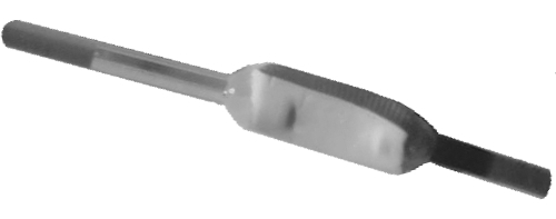
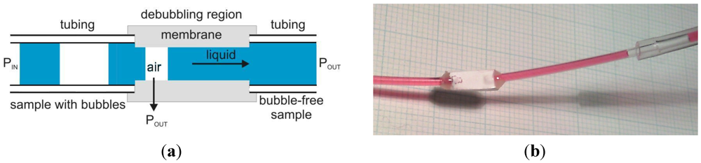
Figure 2 shows the working principle with this inline geometry, with the air flowing through the porous membrane and the liquid flowing further.
Figure 2.
Inline debubbler coupled with tubing. (a) Schematic and operating principle; (b) Picture of demonstration debubbler with air arriving from the right.
Figure 2.
Inline debubbler coupled with tubing. (a) Schematic and operating principle; (b) Picture of demonstration debubbler with air arriving from the right.
A hole of 5 mm length and 0.25 mm in diameter was drilled through the narrow side of the filter plate with a carbide drill of Horley Drill Service Ltd. In addition, at each end of the debubbler a hole of 1.5 mm in diameter was drilled to allow tight fitting of 1/16 inch outer diameter tubing (IDEX, typical inner diameter 0.2 mm). The tubing was glued with Pattex Plastix glue and strengthened with Araldite.
2.2. Design Considerations
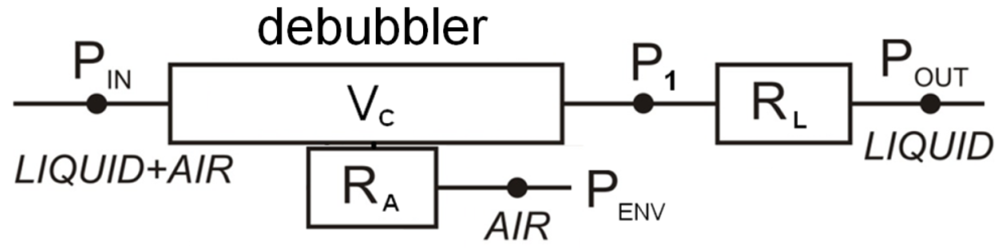
The operation of the devices is depicted in
Figure 3. For a good functionality of the debubblers the liquid flow rate is reduced with a flow restrictor, allowing more air to escape through the filter pores.
Figure 3.
Simple model of the debubbler system. VC is the volume of the debubbler channel and RA is the air flow resistance of the debubbler membrane. RL is a flow restrictor.
Figure 3.
Simple model of the debubbler system. VC is the volume of the debubbler channel and RA is the air flow resistance of the debubbler membrane. RL is a flow restrictor.
Assuming that nearly all the pressure drop of the liquid is over the flow restrictor RL (consisting of a chip and/or capillary), P1 is approximately equal to PIN. Typically POUT is equal or close to the environmental pressure PENV. A large fluidic resistance in the tubing after the debubbler or a high output pressure help to increase the average pressure inside the debubbler. This pressure enables to flush the air through the membrane to the environment before the air plug reaches the end of the debubbler.
The debubbler efficiency depends on the ratio between the liquid flow and the gas flow. We can thus estimate the maximum removable bubble size if we know the air flow resistance of the debubbler membrane. The maximum flow rate ratio ΦA/ΦL depends on the air flow resistances RA of the unwetted debubbler membrane as well as the flow resistance RL. For POUT = PENV and neglecting pressure dynamics,
ΦA/ΦL =RL/RA––– (1)
The air flow resistance is a function of the membrane area that is in contact with the air. The front liquid boundary of the air plug takes a certain time to pass the channel, meanwhile opening up increasingly more of the debubbler membrane to the air. And just before that boundary reaches the end of the membrane, liquid from the other side of the air plug has to meet up with it. Generally the average air flow is much higher than the liquid flow so that we can neglect the time needed to close the gap. The total duration t for maximum bubble size then only depends on the liquid flow ΦL and the channel volume VC. If we now assume that the average air flow through the partly wetted membrane is about half of that through a dry debubbler, we obtain as estimated maximum bubble volume
VA = ½ t ΦA = ½ VC ΦA/ΦL (2)
The channel volume VC depends on its diameter and length. A small internal diameter is desired as this increases the exposure of small air bubbles to the membrane. The length of the debubbler leads to a compromise between system throughput and dead volume. Indeed, a longer debubbler channel will have a higher debubbling capacity but also a larger dead volume. A diameter of 0.25 mm and a length of 5 mm yields a channel volume of 0.25 µL. This sub-microliter dead volume still allows for fast operation of the system, as shown next.
3. Results and Discussion
3.1. First Embodiment
Devices were evaluated with water and air bubbles. The flow rates were adjusted by means of a flow restrictor as well as pressure regulation after the debubbler. The flow restrictor consists of tubing with an inner diameter of 25 µm from IDEX, and its length was adapted to tune the flow rate for a fixed pressure. The water was injected using input pressures in the order of 100 mbar with bubble volumes of around 5 µL and above. The flow rate was measured by observing the flow speed in a tubing of known inner diameter, as done for all experiments.
At 100 mbar inlet pressure and 65 nL/s flow rate, as well as at 10 mbar and 6.5 nL/s flow rate, the integrated debubbler reliably removed air bubbles of 5 µL volume.
The device has also been tested with yeast cells suspended in phosphate buffer saline (PBS). This solution is relevant for many applications, such as cell sorting, impedance spectroscopy and cell lysis [
1,
3]. We verified that at a flow rate of 5 nL/s, bubbles of 5 µL were successfully removed. However, the cell recovery was found to be 10% or less (cell count of sample from inlet: 362, cell count of sample from outlet: 30). We conclude that most of the yeast cells were lost due to sedimentation.
3.2. Second Embodiment
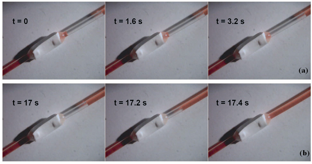
We also tested the second, inline embodiment, whose operation is illustrated in
Figure 4. Air bubbles slowly approach the debubbler until they come in contact with the PTFE membrane, upon which they are quickly expelled.
Figure 4.
Sequence of bubble removal with inline demonstration debubbler, with colored water inside a 1 mm inner diameter tube. (a) 8 µL air bubble approaching debubbler, flow rate ca. 0.2 µL/s; (b) air expulsion through debubbler membrane, observed flow rate up to ca. 25 µL/s.
Figure 4.
Sequence of bubble removal with inline demonstration debubbler, with colored water inside a 1 mm inner diameter tube. (a) 8 µL air bubble approaching debubbler, flow rate ca. 0.2 µL/s; (b) air expulsion through debubbler membrane, observed flow rate up to ca. 25 µL/s.
We tested the bubble volumes that could be fully removed by the debubbler under various conditions, the results being summarized in
Table 1.
Table 1.
Characterization of a tube micro-debubbler at various pressures and flow rates. These values are only estimates as only 5 to 10 bubble volumes have been tested for each condition. The flow rate was adapted by changing the length of the tubing acting as flow restrictor.
Table 1.
Characterization of a tube micro-debubbler at various pressures and flow rates. These values are only estimates as only 5 to 10 bubble volumes have been tested for each condition. The flow rate was adapted by changing the length of the tubing acting as flow restrictor.
| Filter orientation | Inlet pressure [mbar] | flow rate [µL/s] | volume of successfully removed bubble [µL] |
|---|
| vertical | 100 | 1.5 | 6 |
| horizontal | 100 | 1.5 | 10 |
| horizontal | 200 | 0.33 | 15 |
| horizontal | 200 | 0.13 | 63 |
As expected, the performance is better with increased inlet pressure and decreased flow rate so that more air can escape. When placed in a horizontal position the debubbler appears to have a slightly higher debubbling efficiency (maximum bubble volume increases from 6 to 10 µL), which may be due to gravity pushing the shrinking bubble up against the membrane. A vertical position is however preferred for liquids with large particles such as yeast cells. When testing this inline debubbler with yeast cells (suspended in PBS) in vertical position, no cell loss by sedimentation was observed.
We also measured the debubbler’s air resistance by closing the exit of the debubbler, giving an air flow of 45 µL/s at 100 mbar and 90 µL/s at 200 mbar, or 450 nL/s/mbar for 5 mm channel length. Water flowing at 0.13 µL/s will take 1.9 s to go through the 0.25 µL debubbler channel. The expected maximum removable bubble volume is then for 200 mbar ca. 85 µL at 0.13 µL/s and ca. 35 µL at 0.33 µL/s. These estimates are reasonably close to the experimental results.
Both embodiments were tested successfully for several hours of operation without issues. However, in order to prevent biofouling and contamination between different experiments, it may be best to replace the debubbler each time.
4. Conclusions
These simple but effective devices can quickly remove large bubbles from a sample while keeping very low dead volume, which is not possible with conventional systems using bubble traps. A first embodiment is presented in which the debubbler is integrated inside an existing chip holder. It has the advantage to involve no gluing step, but it features horizontal microchannels which can lead to the loss of cells by sedimentation at low flow rates. A second inline embodiment has also been presented, placing the debubbler directly in line with tubing. It can easily be included in any fluidic setup, and can be put in fully horizontal or vertical position.
The debubblers work best at high pressure, low flow rates and in horizontal orientation. However, a vertical inline debubbler is preferred for the treatment of samples with cells.
While we have not observed this, very tiny bubbles could still pass the inline debubbler if their volume allows them to pass without touching the debubbler membrane. For critical applications it may therefore be useful to put our debubbler in series with a small on-chip bubble trap.


