Article

On-Chip Enucleation of Bovine Oocytes using Microrobot-Assisted Flow-Speed Control

1
Department of Micro-Nano Systems Engineering, Graduate School of Engineering, Nagoya University, 1 Furo-cho, Chikusa-ku, Nagoya 464-8603, Japan
2
Department of Aerospace and Mechanical Engineering, University of California, Los Angeles, CA 90095, USA
*
Author to whom correspondence should be addressed.
Micromachines 2013, 4(2), 272-285; https://doi.org/10.3390/mi4020272
Submission received: 1 April 2013 / Revised: 1 June 2013 / Accepted: 6 June 2013 / Published: 21 June 2013
(This article belongs to the Special Issue Micro/Nanofluidic Devices for Single Cell Analysis)

Abstract

:
In this study, we developed a microfluidic chip with a magnetically driven microrobot for oocyte enucleation. A microfluidic system was specially designed for enucleation, and the microrobot actively controls the local flow-speed distribution in the microfluidic chip. The microrobot can adjust fluid resistances in a channel and can open or close the channel to control the flow distribution. Analytical modeling was conducted to control the fluid speed distribution using the microrobot, and the model was experimentally validated. The novelties of the developed microfluidic system are as follows: (1) the cutting speed improved significantly owing to the local fluid flow control; (2) the cutting volume of the oocyte can be adjusted so that the oocyte undergoes less damage; and (3) the nucleus can be removed properly using the combination of a microrobot and hydrodynamic forces. Using this device, we achieved a minimally invasive enucleation process. The average enucleation time was 2.5 s and the average removal volume ratio was 20%. The proposed new system has the advantages of better operation speed, greater cutting precision, and potential for repeatable enucleation.

1. Introduction

“Dolly” is famous for being the first mammal to be successfully cloned from an adult cell [1]. Despite low success rates, several mammalian species have been successfully cloned since then [2,3,4]. Embryo manipulation is a potential technique for the genetic improvement of domestic animals and the preservation of genes of rare animals. Oocyte enucleation is a primary technique for the cloning process. The cloning of Dolly the sheep had a low success rate; 277 eggs were used to create 29 embryos, of which only three resulted in lambs, and eventually only one lived. Peura et al. conducted a viability test of the oocyte volume during nuclear transfer and determined that the nucleocytoplasmic ratio is an important parameter for embryo development [5]. Therefore, the low success rate of cloning techniques is a bottleneck for developing this field. Conventional techniques for the enucleation process mainly include the following: manual manipulator operation, microfluidic cutting methods in a microchip, and chemical treatment methods [6,7,8]. However, these methods tend to have a long operation time, low success rate, contamination, and low repeatability. Additionally, such types of complicated cell manipulation processes can only be undertaken by skilled people. During the chemical treatment processes, a person unaware of toxicities may poison the cells.
Recently, researchers invented many techniques that do not require manual operation for the treatment of cells by fabricating a microrobot on a microchip. Magnetically actuated microrobots appear to be the most promising because of this method is minimally invasive to a cell, features a noncontact drive, and has a low production cost [9,10,11,12,13]. Nelson et al. controlled the untethered microrobots using electromagnetic fields [14]. Sitti et al. designed a biologically inspired miniature robot [15]. These methods reduced the technical skills of operation and increased the throughput and repeatability. These robots can be operated precisely, but they do not have enough power to separate an oocyte. Previously, we have developed magnetically driven microtools (MMTs) in order to apply the microrobot to a wide range of cell manipulations. A permanent magnet possesses a magnetic field that drives an MMT 10–100 times more forcefully than an electromagnetic coil of the same size, effortlessly causing the output of mN-order forces. In order to reduce significantly the effective friction of the MMT, we arranged permanent magnets parallel to the driving plane [16] and piezoelectric ceramics were employed on the drive plane to induce ultrasonic vibrations so that the effective friction reduced significantly [17]. As a result, we achieved μm-order positioning accuracy while maintaining a mN output force.
Enucleation by a dual arm MMT was conducted previously [18]; however, it was difficult to remove the nucleus because the oocyte is a viscoelastic material. The cutting process is a complicated model because the oocyte is soft and sticky. Once the tip of the MMT blade touched the surface of the oocyte, a resistance force generated by the oocyte decreased the position accuracy. In addition, achieving the enucleation process was difficult because the oocyte flow was not well-controlled.
The contribution of this paper is the development of an enucleation system using cooperation of an MMT with fluid control. Our new enucleation system contains three remarkable improvements: the oocyte enucleation process can be conducted one by one; the removal ratio in the volume is controllable, minimizing damage to the oocyte; and the nucleus can be removed with a hydrodynamic force controlled by the MMT. The methods of how to achieve these merits will be introduced sequentially in this manuscript.
Figure 1a shows the concept of the enucleation chip that we used to conduct oocyte enucleation experiments. Two large chambers with a height of 300 μm and a diameter of 5 mm were designed. The MMT with a height of 200 μm was placed in one chamber with its blade inserted in the microchannel branch. To conduct the enucleation process, the other inlet of the Y-shaped microchannel was used to inject continually the oocytes. On the other side of the inlet is a shallow withdrawal microchannel with a height of 50 μm that was used to confine the oocyte to a position to cut accurately the oocyte by a given volume.
The first stage involves oocytes in a cell culture medium being injected from the inlet of the microchip. By connecting a digital pump to the outlet, the medium containing the oocytes from the inlet flowed through the microchamber towards the outlet. The tip of the MMT cutting blade was placed at the interface of the chamber and the withdrawal microchannel. The oocyte was delivered by the flow to the withdrawal microchannel, as shown in Figure 1b. Then, the tip of the MMT controls the oocyte orientation so that the nucleus comes to suction port. The delivered oocyte is obstructed at the interface because of the height limitation (50 μm) of the microchannel, as shown in Figure 1f. Then, the hydraulic pressure deformed the oocyte, allowing the lower part of the oocyte to be suctioned into the withdrawal microchannel, as shown in Figure 1c. After the nucleus was in the withdrawal microchannel, the tip of the MMT was actuated to the left in order to close the interface, as shown in Figure 1d. Next, under the protection of the MMT, the initial portion of the oocyte was reserved and only the separated nucleus was flushed away with the flow (Figure 1e). After the nucleus separated from the oocyte, the remaining part was also sucked out and collected from the outlet. Figure 1f shows the cross-sectional view of the microchannel; there is a height difference between the main chamber and the withdrawal microchannel. The oocyte can be stopped at the intersectional junction where the oocyte enucleation was conducted because of the height difference.
Figure 1. (a) Overview of the enucleation microchip. (be) Concept of the oocyte enucleation process by the use of magnetically driven microtools (MMTs) in a microfluidic chip. Blue arrows show the flow direction. (f) Height differences in the microchannel design. The white arrow shows the movement of the MMT.
Micromachines 04 00272 g001

2. Material and Methods

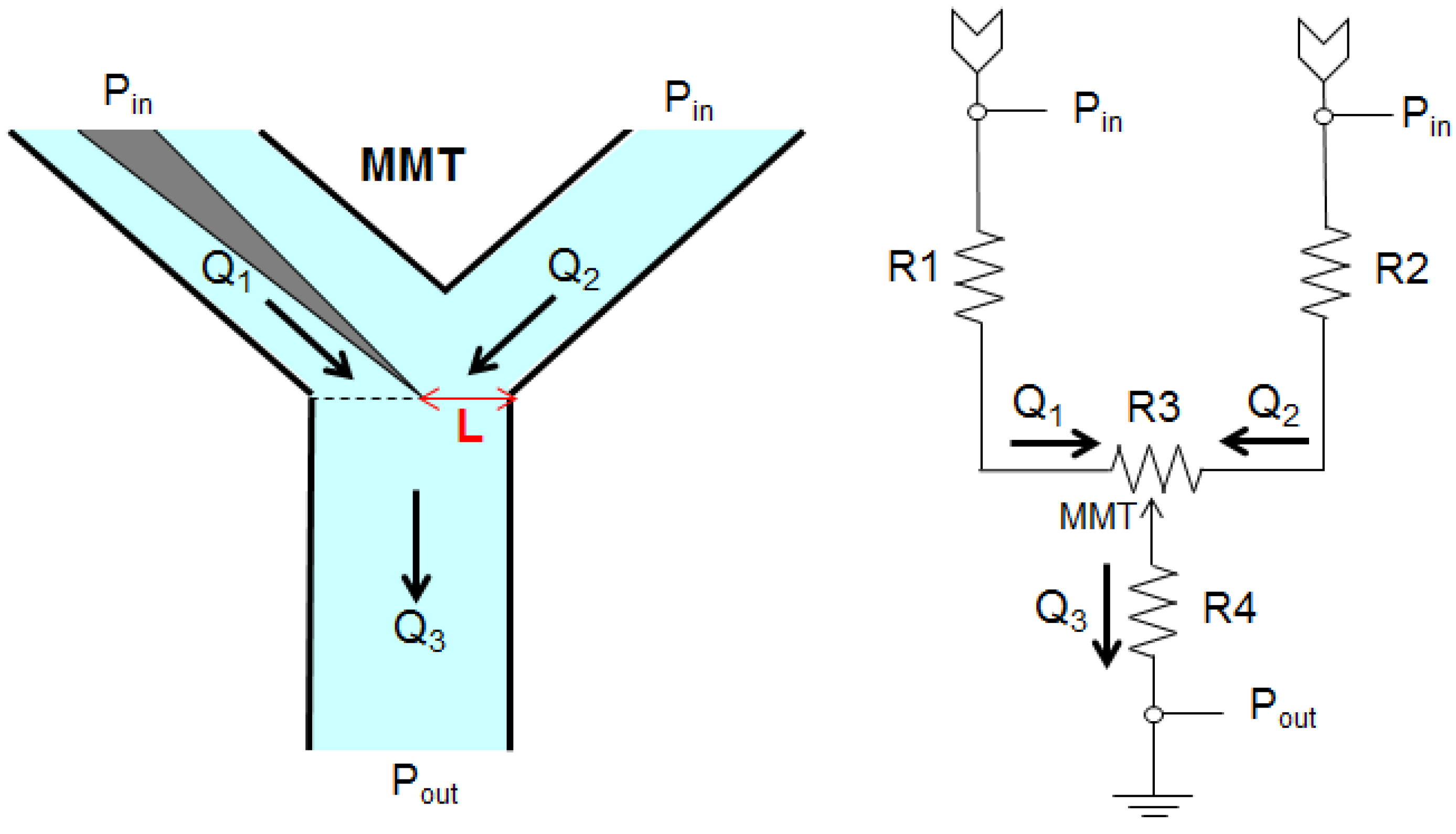
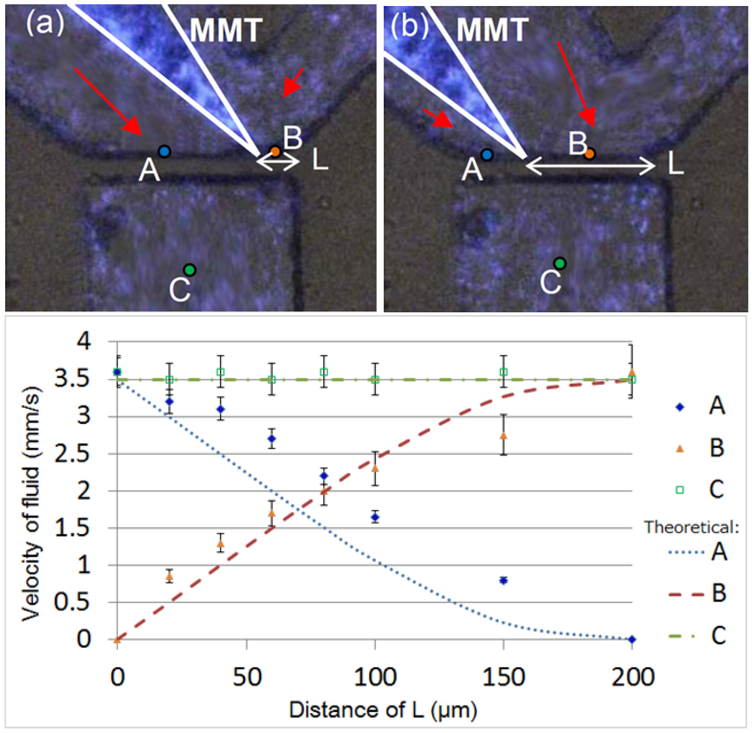
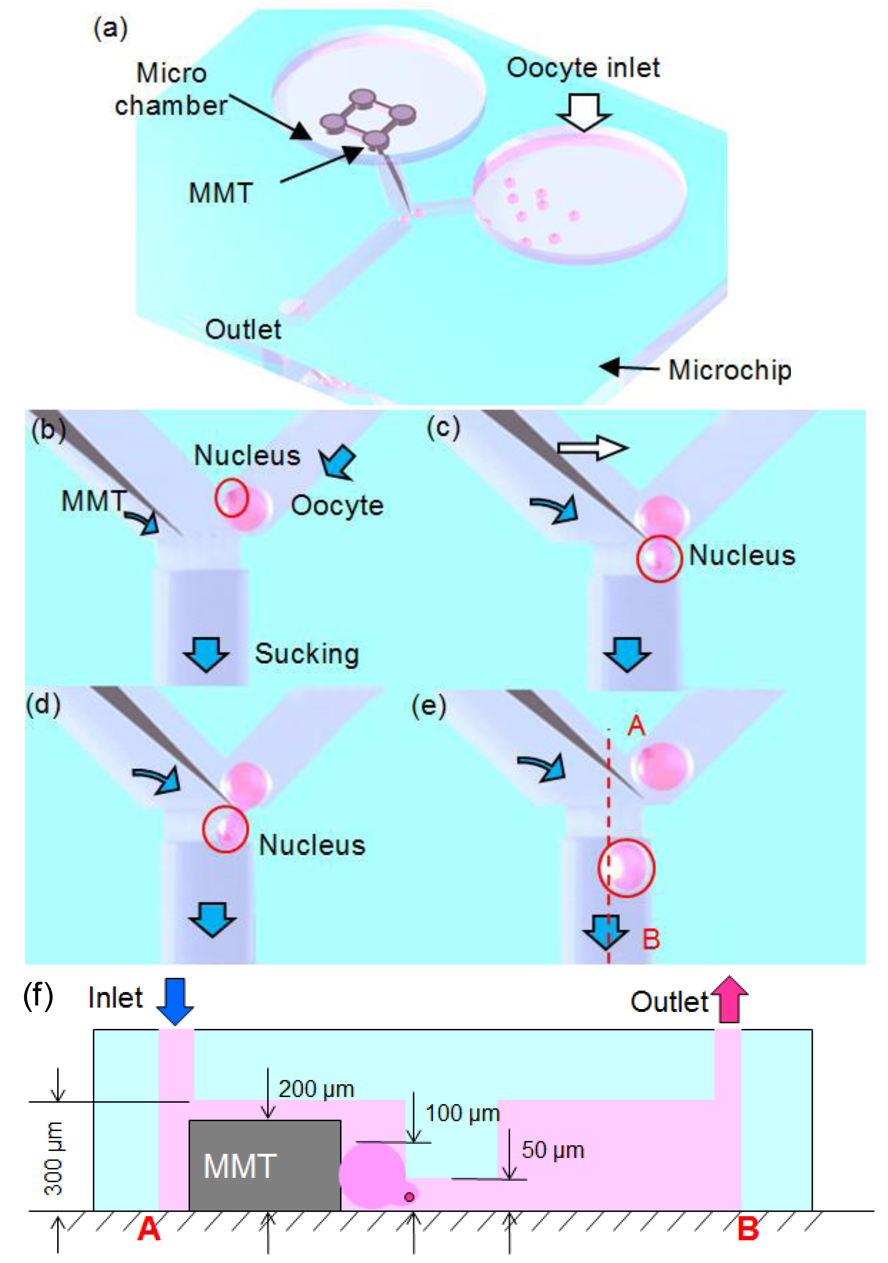
2.1. Fluid Control by MMT

In this enucleation procedure, the nucleus is removed from the oocyte by hydraulic force. The force on a moving object due to a fluid is:
Micromachines 04 00272 i001
where FD is the drag force, ρ is the density of the fluid, v is the speed of the object relative to the fluid, Cd is the drag coefficient, and A is the reference area. As evidenced in the equation, the drag force is relative to the velocity of the fluid. Therefore, in order to utilize the flow effectively for the oocyte enucleation process, the local velocity of the fluid must be precisely controlled by MMT; this method is proposed below.
In representing the flow of a fluid as the flow of electricity, some insight into the process is gained; the fluid in a hydraulic circuit behaves similar to electrons in an electrical circuit. An electric circuit analogy is used in Figure 2 to specify the parameters of the microchannel [19]. The total volumetric flow rate Q (m3/s) in a rectangular microchannel is described by Hagen–Poiseuille’s law [20] as
Micromachines 04 00272 i002
Micromachines 04 00272 i003
where ∆p is the pressure difference (Pa) through a finite channel length L. The hydraulic resistance RH (Pa s3/m) is defined as
Micromachines 04 00272 i004
where η is the viscosity (Pa s). The hydraulic radius of the channel rʜ (m) is a geometric constant and is defined as rʜ = 2A/P, where A is the cross-sectional area of the channel (m2) and P is the wetted perimeter (m).
Based on the equations mentioned above, we determined that the structure of the microchannel strongly influences the volumetric flow rate. The area-averaged velocity of the fluid U (m s1) is [21]:
Micromachines 04 00272 i005
where w and h are the width and the height of the microchannel, respectively. By changing the position of the MMT, the microchannel structures on both sides are slightly modified. Therefore, the fluid distribution is actively controlled by the MMT. By employing the MMT-controlled fluid, the oocytes can be individually delivered to the suction port. Considering oocytes are typically 100 μm in diameter, the oocyte inlet microchannel is 150 μm in width, and length is 300 μm. Because the height of the MMT is 200 μm, the chamber height and width are both 300 μm, and to confine the oocyte at the suction port. In order to have allowed the MMT enough space to conduct all the processes, the MMT works similar to a rheostatic controller, which is governed by the distribution of flow, Q2 and Q3. The flow allows the oocyte to load to the location of operation, i.e., separating the nucleus from the oocyte, by increasing the hydraulic pressure.
We conducted the experiments by loading fluorescent microbeads (Ф: 2 µm) into the microfluidic chip to demonstrate the effectiveness of the MMT movements on the velocity of the fluid. Figure 3 shows the fluid velocity with respect to the position changes of the MMT. In Figure 3a, when the MMT is near the right-side corner of the withdrawal microchannel, the velocity of fluid on the left side is higher than on the right side of the MMT. In Figure 3b, when the MMT is near the left side, the velocity of fluid in the microchannel on the right side is higher than on the left side. Three representative points were selected to assess the velocity distribution in the microchannel. The pressure distribution on the oocyte was derived from the velocity distribution. Points A and B show the distribution of velocity on both sides of the MMT at the suction port, while point C was used to the observe velocity changes in the suction channel. The width of the microchannel is 200 µm and we measured the distance L at points along the range of 0–200 μm. Figure 3c shows the experimental results as well as the theoretical results for the fluid velocity changes with respect to the MMT position at each point. When the position of the MMT was at the right edge of the channel (L = 0 μm), the flow from the right side of the channel ceased, whereas when the position of the MMT was at the left edge of the channel (L = 200 μm), the flow from the left side ceased. The experimental values reasonably corresponded to the theoretical values, proving that the flow distribution in the channel was well-controlled by the MMT position, similar to an adjustable valve. As a result, the surface traction forces (FD) affecting the oocyte can be adjusted to conduct the oocyte enucleation process by allowing the oocyte to split via the hydraulic force and to be flushed away by the flow.
Figure 2. Electric circuit analogy of the enucleation chip.
Micromachines 04 00272 g002
Figure 3. Theoretical and experimental values of the fluid velocity changes at three points in the channel. The velocity of the outflow is set to 3.5 mm/s. (a) In case that the MMT is near the right-side corner, (b) In case that the MMT is the left-side corner.
Micromachines 04 00272 g003

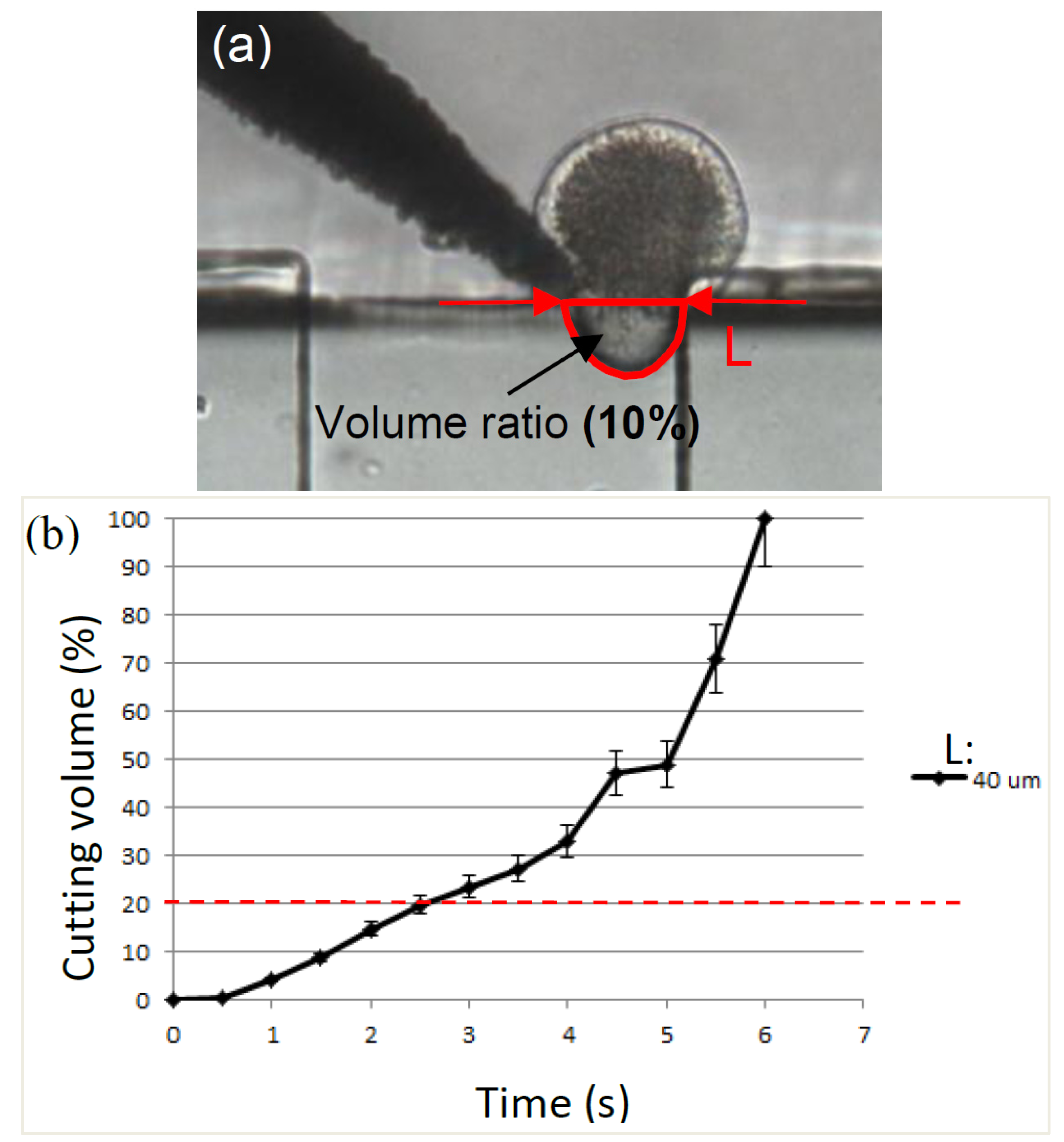
2.2. Cutting Volume Estimation

In order to achieve precise separation of the nucleus from the oocyte with minimal damage, the effect of the oocyte removal volume is significant. It is crucial to remove the nucleus in the smallest volume possible to increase the potential for the development of the nuclear transfer embryos [22]. The MMT controls the volume of the suctioned oocyte by closing the channel after a certain amount of time. To determine the correlation between the suction time and the oocyte volume suctioned into the channel, experiments were conducted.
In the experiment, the outlet velocity (point C in Figure 3) was fixed to avoid interference from the pump. The outlet of the polydimethylsiloxane (PDMS) chip was connected to a syringe pump using a Teflon tube. The relationship between the oocyte volume sucked into the outlet microchannel and the suction time was obtained. The distance between the MMT tip and the right edge of the withdrawal microchannel, L in Figure 4, can vary, which would result in a change in the velocity of the sucked volume. In our experiment, the MMT position was fixed at a distance of 40 μm from the right edge of the channel, and the oocyte with a nucleus had enough space to be suctioned into the withdrawal microchannel. The suctioned volume of the oocyte was measured by the oocyte area in the channel and the height of the channel (Figure 4a). Figure 4b shows the experimental results of the volume ratio of the sucked volume into the channel to the original oocyte volume with respect to time. The graph shows that the error bars at each data point are small. Especially, the volume suctioned in the channel in less than 3 s was consistent and the variation was less than 5%. This indicates that the volume control over time using an MMT and fluid forces is highly accurate, enabling a precise enucleation process.
Figure 4. Correlations of the volume sucked into the outlet microchannel with respect to the time under the fixed position of the MMT. The velocity of the outflow is set to 3.5 mm/s. (a) The definition of volume ratio, (b) the experimental result.
Micromachines 04 00272 g004

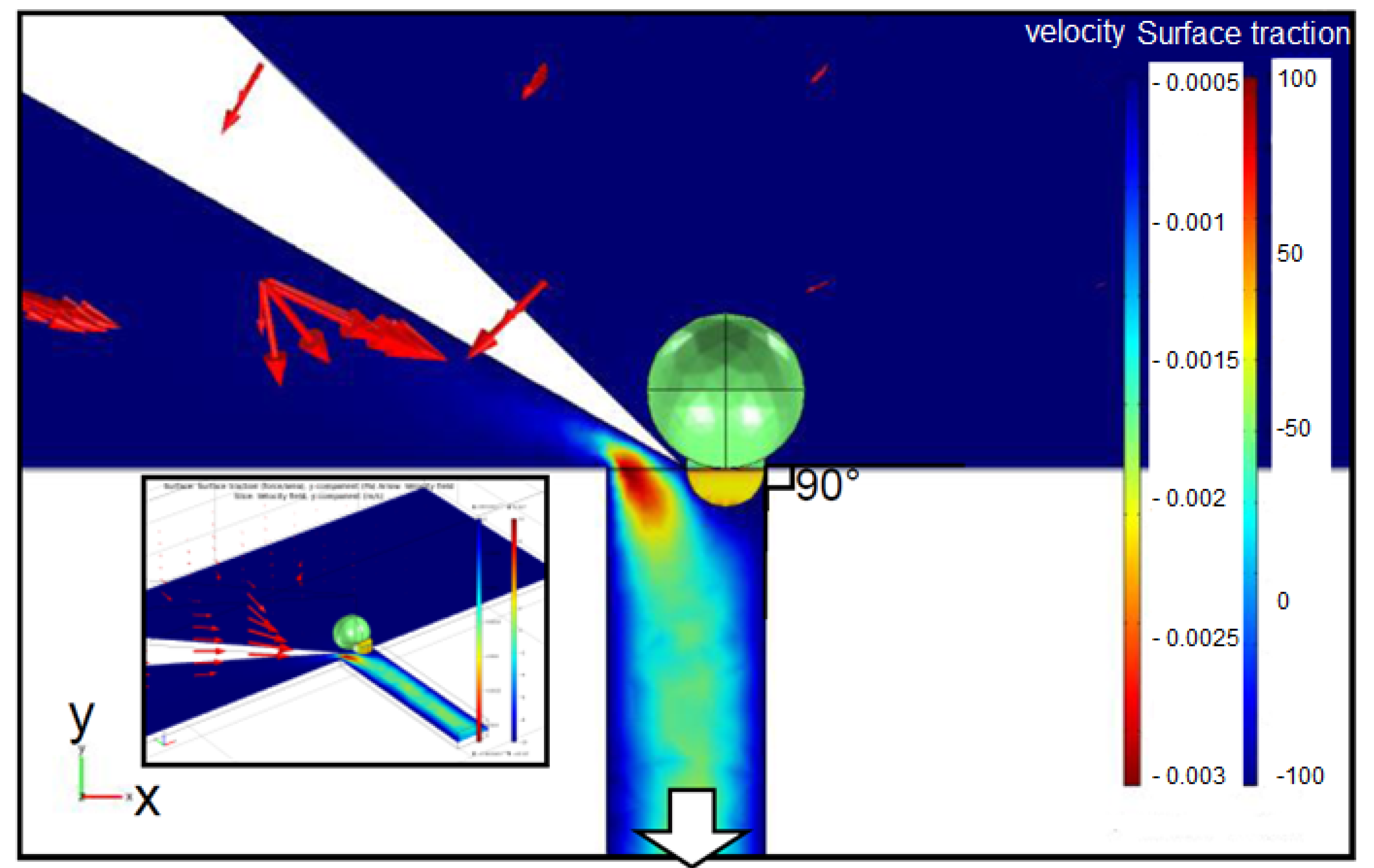
2.3. Separation of Oocyte by Hydraulic Force

Separating an oocyte using two MMTs is difficult because the perfect alignment of two cutting edges is difficult [17]. Therefore, we propose a new cutting method employing only one MMT. We squeeze an oocyte using an MMT towards the wall of the microchannel, allowing the nucleus portion to be separated by fluidic forces. A 3D structure was modeled using COMSOL Multiphysics 4.1 to analyze the distribution of the surface traction on the oocyte; this model also allowed the flow conditions in the microchannel to be observed. The MMT angle and the exit velocity are set to 150° and 3.5 mm/s, respectively. Figure 5 shows the COMSOL simulation results; from this figure, the surface traction on the oocyte is completely different with respect to the velocities in separate areas. The lower part of an oocyte that enters the withdrawal microchannel suffers a high traction force with a maximum value of 72.2 Pa from the hydraulic pressure in the Y-direction. Meanwhile, the part that is not being suctioned into the microchannel experiences almost 0 Pa because it is protected by the MMT from the impact of the medium.

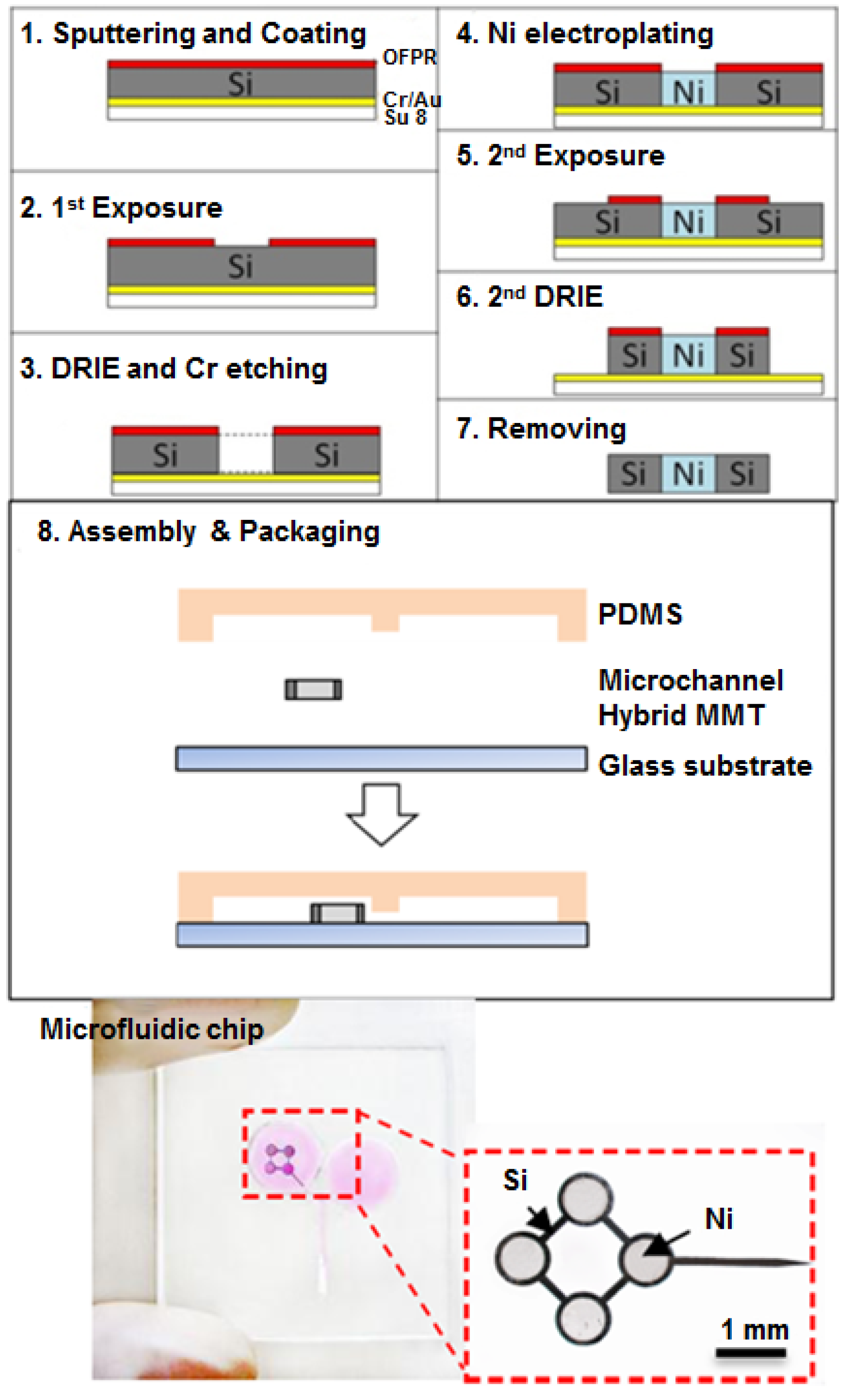
2.4. Fabrication of Hybrid MMT and Microfluidic Chip

A microfluidic chip consists of a PDMS microchannel and is bonded to a glass substrate. A PDMS microchannel was produced via replica molding with a photolithography-fabricated master mold. Ultraviolet light was exposed through a photomask to produce a microchannel pattern using a mask aligner (LA410, Nanometrich Technology Inc., Tokyo, Japan). The substrate was then developed and rinsed. We employed SU-8 film (DuPont Co., Wilmington, DE, USA) and a two-step exposure process to produce the height difference in the microchannel of the microfluidic chip. The two-step exposure was performed to fabricate a precise and uneven channel for cell confinement. The main channel and the withdrawal microchannel had heights of 300 μm and 50 μm, respectively.
Ni is ferromagnetic and can be magnetically attracted by a permanent magnet, but it is easy to bend during handling because of its ductility and thinness. As a result, smooth Ni is difficult to maintain, which is essential for flow control in the channel. Therefore, we employed a hybrid MMT composed of Ni and Si, which is both rigid and bio-compatible. The Ni-Si MMT fabrication process is shown in Figure 6. At first, Au and then Cr were sputtered onto the Si wafer (thickness = 200 μm). Then, the wafer was coated with a thick negative photoresist (SU-8, Tokyo Ohka Kogyo Co., Kanagawa, Japan) and then exposed on the Si substrate so it could be utilized as a support layer. The other side of the Si wafer was coated with the photoresist OFPR (Tokyo Ohka Kogyo Co., Kanagawa, Japan). After the exposure on the OFPR side, the OFPR pattern was developed. Next, deep reactive-ion etching (DRIE) was conducted on the OFPR side, and the Si was etched to a depth of 200 μm, until the Cr/Au layer stopped the etching process. After the wet etching of the Cr, the Au surface was exposed. Then, Ni was grown on the Au surface by the electroplating method to a thickness of 200 μm. After the Ni accumulated in the holes on the Si substrate, we again conducted the OFPR coating, exposure, and DRIE processes to form the MMT shape. At last, by removing the photoresist and the Au layer, a hybrid MMT was fabricated.
In order to prevent contamination after 2–3 h experiments, one disposable microfluidic chip that costs only 0.2 dollars was available. However, the MMT could be repeatedly cleaned and reused.
Figure 5. FEM results of the velocity distribution and the surface traction of oocytes in the Y-direction. Object surface: y component of surface traction (force/area) (Pa). Arrow: Velocity field, Slice: y component of velocity field (m/s).
Micromachines 04 00272 g005
Figure 6. Fabrication process of the MMT and a fabricated chip with a magnified figure of the MMT.
Micromachines 04 00272 g006

3. Oocyte Enucleation Experiments

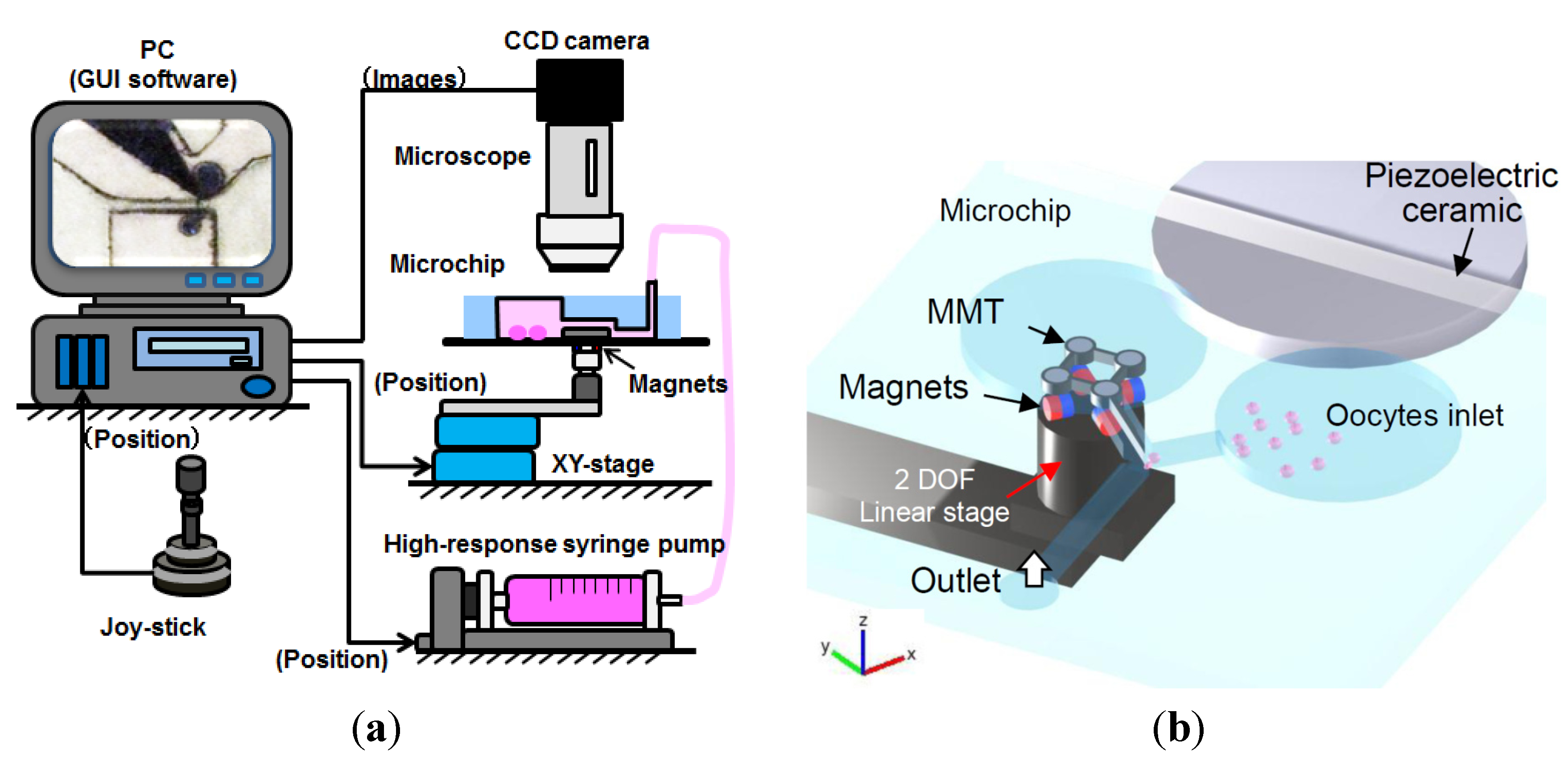
3.1. Experimental Setup

Figure 7a shows the system components of the platform, including a linear stage for the magnet actuation, a microscope with a CCD camera, a joystick, a high-response pump, and a microfluidic chip. The microscope with the CCD camera sends the captured image data to the PC and the stage movement is controlled by the joystick. A high-response syringe pump connected to the microchip is used to control the velocity in the microchannel.
Figure 7b shows the overview of the microchip setup, including the driving concept of the MMT using horizontal polar drive (HPD) with ultrasonic vibration [17]. The MMT is actuated by HPD and the four neodymium (Nd2Fe14B) (diameter: 1.0 mm, grade: N40) permanent magnets, which are arranged on a swivel base set on a 2 degrees-of-freedom (DOF) linear stage [16]. The commercially available piezoelectric ceramic (W-40, MKT Taisei Co., Tokyo, Japan) has the following parameters: the size is φ = 42.0 × 3.5 mm; the resonance frequency is 55 kHz; and the electrostatic capacitance is 4600 pF. This was attached to the microfluidic chip and an AC of 150 Vp-p was applied at 52.5 kHz to vibrate the sliding surface of the MMTs [17]. By controlling the 2-DOF linear stage, the MMT could be actuated in the X- and Y-directions. The swivel base rotated the MMT in the X-Y plane. In summary, an MMT with 3-DOF on the X-Y plane is sufficient for performing the enucleation process.
Figure 7. Components of experimental system: (a) experimental setup for the enucleation of oocytes including the linear stage for magnet actuation, a microfluidic chip, and a piezoceramic for generating vibrations on the microfluidic chip and (b) system architecture.
Micromachines 04 00272 g007

3.2. Experimental Process and Result

Prior to the oocyte enucleation process, the bovine oocyte must be prepared in advance with hyaluronidase (0.1% of medium) for 10 min in order to remove the cumulus cells surrounding the oocytes and pronase (0.5% of Phosphate buffered saline) for 10 min to remove the zona pellucida. Next, Hoechst 34580 is applied to stain the nucleus of the oocyte; the nucleus portion was florescent when exposed to a mercury lamp.
Figure 8 shows the experimental results of the bovine oocyte enucleation process (Supplemental video file available online). The oocyte inserted from the inlet flowed to the narrow channel. The MMT pushed the oocyte towards the wall of the microchannel so the oocyte orientation could be adjusted by letting the nucleus face towards the suctioning microchannel. The oocyte was too large to pass into the microchannel with a height of 50 μm (Figure 8a). After the nucleus position was confirmed, the downside of the oocyte was drawn towards the withdrawal microchannel by the outward flow until the nucleus, visualized by the bright spot, was sucked in the channel (Figure 8b). Then, the tip of the MMT held the oocyte by pressing it towards the corner of the channel (Figure 8c). Next, the lower part of the oocyte with the nucleus was torn by hydraulic forces and was washed away with the outward flow (Figure 8d). After the separation experiments, the remainder of the oocytes were suctioned from the outlet and immediately sent to an extraction chamber to evaluate the status of the cell membranes. Although deformation of the oocyte could happen during the separation process, Figure 8e shows that the cell membrane of the enucleated oocyte, which is spherical, remained intact. The removed nucleus can also be observed in this figure. The nucleus was successfully removed and the oocyte shape remained circular, even after the separation. The procedure time, i.e., the duration from the oocyte reaching the narrow channel until the nucleus was removed from the oocyte, was less than 5 s and the volume removed from the oocyte is approximately 17.8% of the original volume.
Figure 8. (ad) Experimental results of the oocyte enucleation process with an MMT. (e) Nucleus after being removed from the oocyte. The incision of the enucleated oocyte is smooth and the remaining oocyte is remains smooth; the enucleated nucleus is also shown in this figure with a removal volume of 17.8% from the original volume. (Supplemental Video file available online).
Micromachines 04 00272 g008

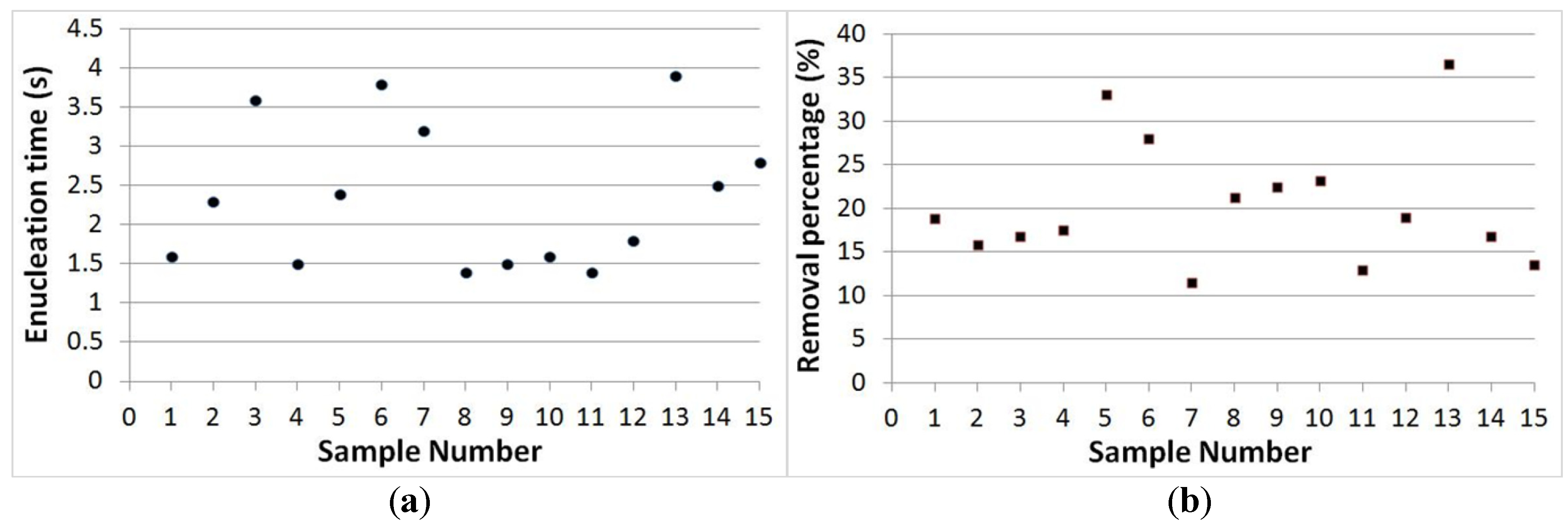
3.3. Separation Time and Removal Proportion Evaluation

The dot graphs of Figure 9 show the evaluations of both the enucleation time and the removal proportion of oocytes based on 15 samples. Figure 9a shows that the enucleation time was an average of 2.5 s for a single oocyte enucleation. The slowest processing time was less than 5 s. In mammalian cells, the average diameter of the nucleus is approximately 6 μm, which occupies about 10% of the total cell volume [23]. Using our approach, the removal volume of the oocyte was 20% on average; the 20% removal of the cytoplasm ratio is significant for early cloned bovine embryos [22]. Depending on the nucleus position, the removal volume can be slightly increased, but the highest volume removed was 36%. The precise control of oocyte orientation in a few seconds assists in improving the separation accuracy, which will be further covered in our future work.
Figure 9. (a) Enucleation processing time for 15 samples; the average enucleation time is 2.5 s for one oocyte. (b) Removal proportion of the nucleus from the original oocyte for 15 samples; the average removal proportion is 20%.
Micromachines 04 00272 g009

4. Conclusions

A new scheme that involves use of hydraulic forces controlled by a microrobot to perform an oocyte enucleation process in a microfluidic chip has been demonstrated. Using this novel design for oocyte enucleation, the nucleus was removed from the oocyte successfully. This system is advantageous for the following three reasons: (1) that oocyte enucleation can be conducted at a higher speed as compared to conventional enucleation methods; (2) that it minimizes the damage to the oocyte, and that the removal volume of the nucleus portion is small, which is important because the cytoplasmic volume affects the development of nuclear transfer embryos; and (3) that the incision of the enucleated oocyte is smooth, which may also reduce the influence of the viability on the oocyte. Viability examinations of enucleated oocyte by proposed method are our ongoing work. However, the advantage of separating an oocyte by fluid force is confirmed by Ichikawa et al. [7].
The precise and faster orientation control of the oocyte needs to be studied more because it takes several seconds to minutes to properly orient the oocyte positions. Then, the next step is a fusion process using the enucleated oocyte. After this, our study will include a repeatable enucleation process via more automatic control. For instance, automatically detecting oocytes and adding a dispensing module, which could dispense the enucleated portion to the culture automatically, will achieve high-speed, high-precision, and repeatable results. This work will conclude with the automation of the oocyte enucleation process, similar to a manufacturing production line.

Acknowledgements

This work is partially supported by SENTAN, JST; the Nagoya University Global COE program for Education and Research of Micro-Nano Mechatronics; and Scientific Research from the Ministry of Education, Culture, Sports, Science and Technology (25630090).

Conflict of Interest

The authors declare no conflict of interest.

References

  1. Lassen, J.; Gjerris, M.; Sandøe, P. After Dolly—Ethical limits to the use of biotechnology on farm animals. Theriogenology 2005, 65, 992–1004. [Google Scholar] [CrossRef]
  2. Edwards, J.L.; Schrick, F.N.; McCracken, M.D.; van Amstel, S.R.; Hopkins, F.M.; Welborn, M.G.; Davies, C.J. Cloning adult farm animals: A review of the possibilities and problems associated with somatic cell nuclear transfer. Am. J. Reprod. Immunol. 2003, 50, 113–123. [Google Scholar] [CrossRef]
  3. Vanderwall, D.K.; Woods, G.L.; Aston, K.I.; Bunch, T.D.; Li, G.P.; Meerdo, L.N.; White, K.L. 76 cloned horse pregnancies produced using adult cumulus cells. Reprod. Fertil. Dev. 2003, 16, 160–160. [Google Scholar]
  4. Schramm, R.D.; Paprocki, A.M. Strategies for the production of genetically identical monkeys by embryo splitting. Reprod. Biol. Endocrinol. 2004, 2, 38. [Google Scholar] [CrossRef]
  5. Peura, T.T.; Lewis, I.M.; Trounson, A.O. The effect of recipient oocyte volume on nuclear transfer in cattle. Mol. Reprod. Dev. 1998, 50, 185–191. [Google Scholar] [CrossRef]
  6. Wang, H.L.; Chang, Z.L.; Li, K.L.; Lian, H.Y.; Han, D.; Cui, W.; Tan, J.H. Caffeine can be used for oocyte enucleation. Cell. Reprogramming 2011, 13, 225–232. [Google Scholar] [CrossRef]
  7. Ichikawa, A.; Tanikawa, T.; Akagi, S.; Ohba, K. Automatic cell cutting by high-precision microfluidic control. J. Rob. Mechatron. 2011, 23, 13–18. [Google Scholar]
  8. Costa-Borges, N.; Paramio, M.T.; Calderón, G.; Santaló, J.; Ibáñez, E. Antimitotic treatments for chemically assisted oocyte enucleation in nuclear transfer procedures. Cloning Stem Cells 2009, 11, 153–166. [Google Scholar] [CrossRef]
  9. Barbic, M.; Mock, J.J.; Gray, A.P.; Schultz, S. Electromagnetic micromotor for microfluidics applications. Appl. Phys. Lett. 2001, 79, 1399–1401. [Google Scholar] [CrossRef]
  10. Mensing, G.A.; Pearce, T.M.; Graham, M.D.; Beebe, D.J. An externally driven magnetic microstirrer. Phil. Trans. R. Soc. Lond. A 2004, 362, 1059–1068. [Google Scholar] [CrossRef]
  11. Atencia, J.; Beebe, D.J. Magnetically driven biomimetic micro pumping using vortices. Lab Chip 2004, 4, 598–602. [Google Scholar] [CrossRef]
  12. Roper, M.; Dreyfus, R.; Baudry, J.; Fermigier, M.; Bibette, J.; Stone, H.A. On the dynamics of magnetically driven elastic filaments. J. Fluid Mech. 2006, 554, 167–190. [Google Scholar] [CrossRef]
  13. Gao, L.; Gottron, N.J., III; Virgin, L.N.; Yellen, B.B. The synchronization of superparamagnetic beads driven by a micro-magnetic ratchet. Lab Chip 2010, 10, 2108–2114. [Google Scholar] [CrossRef]
  14. Zhang, L.; Abbott, J.J.; Dong, L.; Kratochvil, B.E.; Bell, D.; Nelson, B.J. Artificial bacterial flagella: Fabrication and magnetic control. Appl. Phys. Lett. 2009, 94, 064107. [Google Scholar] [CrossRef]
  15. Park, H.S.; Floyd, S.; Sitti, M. Roll and pitch motion analysis of a biologically inspired water runner robot. Int. J. Rob. Res. 2010, 29, 1281–1297. [Google Scholar] [CrossRef]
  16. Hagiwara, M.; Kawahara, T.; Yamanishi, Y.; Arai, F. Driving method of microtool by horizontally arranged permanent magnets for single cell manipulation. Appl. Phys. Lett. 2010, 97, 013701. [Google Scholar] [CrossRef]
  17. Hagiwara, M.; Kawahara, T.; Yamanishi, Y.; Masuda, T.; Feng, L.; Arai, F. On-chip magnetically actuated robot with ultrasonic vibration for single cell manipulations. Lab Chip 2011, 11, 2049–2054. [Google Scholar] [CrossRef]
  18. Hagiwara, M.; Kawahara, T.; Yamanishi, Y.; Arai, F. Precise control of magnetically driven microtools for enucleation of oocytes in a microfluidic chip. Adv. Rob. 2011, 25, 991–1005. [Google Scholar] [CrossRef]
  19. Oh, K.W.; Lee, K.; Ahn, B.; Furlani, E.P. Design of pressure-driven microfluidic networks using electric circuit analogy. Lab Chip 2012, 12, 515–545. [Google Scholar] [CrossRef]
  20. Pfitzner, J. Poiseuille and his law. Anaesthesia 1976, 31, 273–275. [Google Scholar] [CrossRef]
  21. Cornish, R.J. Flow in a pipe of rectangular cross-section. Proc. R. Soc. Lond. A 1928, 120, 691–700. [Google Scholar] [CrossRef]
  22. Hua, S.; Zhang, H.; Su, J.M.; Zhang, T.; Quan, F.S.; Liu, L.; Wang, Y.S.; Zhang, Y. Effects of the removal of cytoplasm on the development of early cloned bovine embryos. Anim. Reprod. Sci. 2011, 126, 37–44. [Google Scholar] [CrossRef]
  23. Alberts, B.; Johnson, A.; Lewis, J.; Raff, M.; Roberts, K.; Walter, P. DNA and Chromosomes. In Molecular Biology of the Cell, 4th ed.; Garland Science: New York, NY, USA, 2002; pp. 191–234. [Google Scholar]

