Article

Design of a Weighted-Rotor Energy Harvester Based on Dynamic Analysis and Optimization of Circular Halbach Array Magnetic Disk

1
Department of Mechanical and Electromechanical Engineering, National Sun Yat-sen University, No. 70 Lienhai Rd., Kaohsiung 80424, Taiwan
2
Nuvoton Technology Corporation, No. 4, Creation Rd., Hsinchu Science Park 30077, Taiwan
3
Department of Mechanical Engineering, National Taipei University of Technology, No. 1, Sec. 3, Zhongxiao E. Rd., Taipei 10608, Taiwan
*
Author to whom correspondence should be addressed.
Micromachines 2015, 6(3), 375-389; https://doi.org/10.3390/mi6030375
Submission received: 26 December 2014 / Revised: 15 March 2015 / Accepted: 18 March 2015 / Published: 23 March 2015
(This article belongs to the Special Issue Power MEMS)

Abstract

:
This paper proposes the design of a weighted-rotor energy harvester (WREH) in which the oscillation is caused by the periodic change of the tangential component of gravity, to harvest kinetic energy from a rotating wheel. When a WREH is designed with a suitable characteristic length, the rotor’s natural frequency changes according to the wheel rotation speed and the rotor oscillates at a wide angle and high angular velocity to generate a large amount of power. The magnetic disk is designed according to an optimized circular Halbach array. The optimized circular Halbach array magnetic disk provides the largest induced EMF for different sector-angle ratios for the same magnetic disk volume. This study examined the output voltage and power by considering the constant and accelerating plate-rotation speeds, respectively. This paper discusses the effects of the angular acceleration speed of a rotating wheel corresponding to the dynamic behaviors of a weighted rotor. The average output power is 399 to 535 microwatts at plate-rotation speeds from 300 to 500 rpm, enabling the WREH to be a suitable power source for a tire-pressure monitoring system.

1. Introduction

An energy harvester converts ambient energy into electricity to drive small autonomous devices such as sensors. Researchers have built and tested vibration-based generators by using three types of transducer: electromagnetic, electrostatic, and piezoelectric. Roundy [1] demonstrated that electromagnetic and piezoelectric harvesting mechanisms have a higher energy storage density than that of electrostatic mechanisms. Electromagnetic harvesting mechanisms provide favorable energy density and high reliability and do not require a separate voltage source. Furthermore, energy harvesters that involve this mechanism are compatible with many types of vibrational mode including rotation, oscillation, and hybrid vibrations [2].
A tire-pressure monitoring system (TPMS) is a device integrated with the pressure sensor, the radio frequency module, the analog-to-digital converter, and the temperature sensor to monitor the pressure inside the tire. A TPMS is typically powered by a lithium battery, which exhibits a limited lifespan, thus constituting an inconvenience for the end user. Therefore, research aimed at developing energy-harvesting devices for use in TPMSs has expanded in recent years [3,4,5]. Harvesting energy from tire rotation and from road vibrations are two widely adopted methods for powering a TPMS. The frequency of the external force applied on the wheel is varied with the wheel rotation speed. Hence, a wide bandwidth or similar frequency-adjusting energy-harvesting mechanism is necessary. To adjust the resonance frequency of the energy harvester, Leland et al. [6] presented a tunable-resonance vibration energy scavenger that axially compresses a piezoelectric bimorph to lower its resonance frequency. The compressive axial preload of the piezoelectric energy is adjusted manually. Stanton et al. [7] validated the use of a nonlinear energy harvester capable of bidirectional hysteresis, in which both hardening and softening responses within the quadratic potential field of a power-generating piezoelectric beam (with a permanent magnet end mass) are induced by tuning the nonlinear magnetic interactions. The development of a wide-bandwidth energy-harvesting device is a current research topic [8,9,10,11,12,13,14,15].
Research into energy harvesters with wide-bandwidth characters for TPMS applications is progressing. Kanwa et al. [16] developed an energy harvester mounted on the inner tire, demonstrating power generation capabilities sufficient for transmitting tire sensor data multiple times per minute. Wang et al. [17] developed a pendulum-based energy harvester for harvesting energy from a rotating wheel. A seesaw-structured energy harvester for TPMS applications was proposed by Xuan et al. [18]. This design, which can effectively circumvent the influence of enormous centrifugal forces, was tested with an average power of 5.625 μW at 750 rpm. A non-contact piezoelectric energy harvester to generate 3.5 μW at 333 rpm from centripetal force is proposed by Ghaithaa et al. [19]. In order to power TPMS, a piezofiber energy harvester mounted inside the tire to provide 34.5 μJ for one wheel cycle was developed [20]. Although relatively broad bandwidths were achieved in these studies, energy harvesters used in TPMSs should be lightweight and demonstrate sufficient output power at different wheel speeds and accelerations. The TPMS P420A [21] produced by Orange Electronics consumes an average power of 29.6 μW that is measured by a power detector circuit. Considering the power consumption of the TPMS and 30% efficiency of the storage circuit, the output power of the energy harvester should be greater than 100 μW.
We propose a weighted-rotor energy harvester (WREH) demonstrating a wide-bandwidth energy-harvesting capability for TPMS applications. The characteristic length of a weighted rotor is adjusted using an adjustable screw to make the natural frequency of the weighted rotor meet the wheel rotation frequency. The well-weighted rotor, which exhibits no jump phenomenon at huge car acceleration speed, is approved in the dynamic analysis section. Previous research [22] has only considered the constant car speed. The magnetic flux density varied with the sector-angle ratio of the circular Halbach array magnetic disk is analyzed. We propose a novel optimized sector-angle ratio rather than a traditional 1:1 ratio to enhance the electromotive force. The optimized sector-angle arrangement could achieve a suitable electromagnetic damping value in the smallest volume of the magnetic disk. The transient response and output voltage of WREH are provided in the numerical results and experiment when the plate-rotation speed was accelerated. The remainder of this paper is organized as follows: Section 2 presents detailed simulations of the weighted rotor based on various parameters and wheel accelerations, and the optimization of the circular Halbach array magnetic disk. Section 3 presents the construction of power generation equations, the experimental setup, and comparisons between the numerical and the experimental results of using the prototype, regarding power generation at different wheel speeds under various acceleration conditions. Finally, the conclusion of this study is provided in Section 4.

2. Overall Design of the WREH

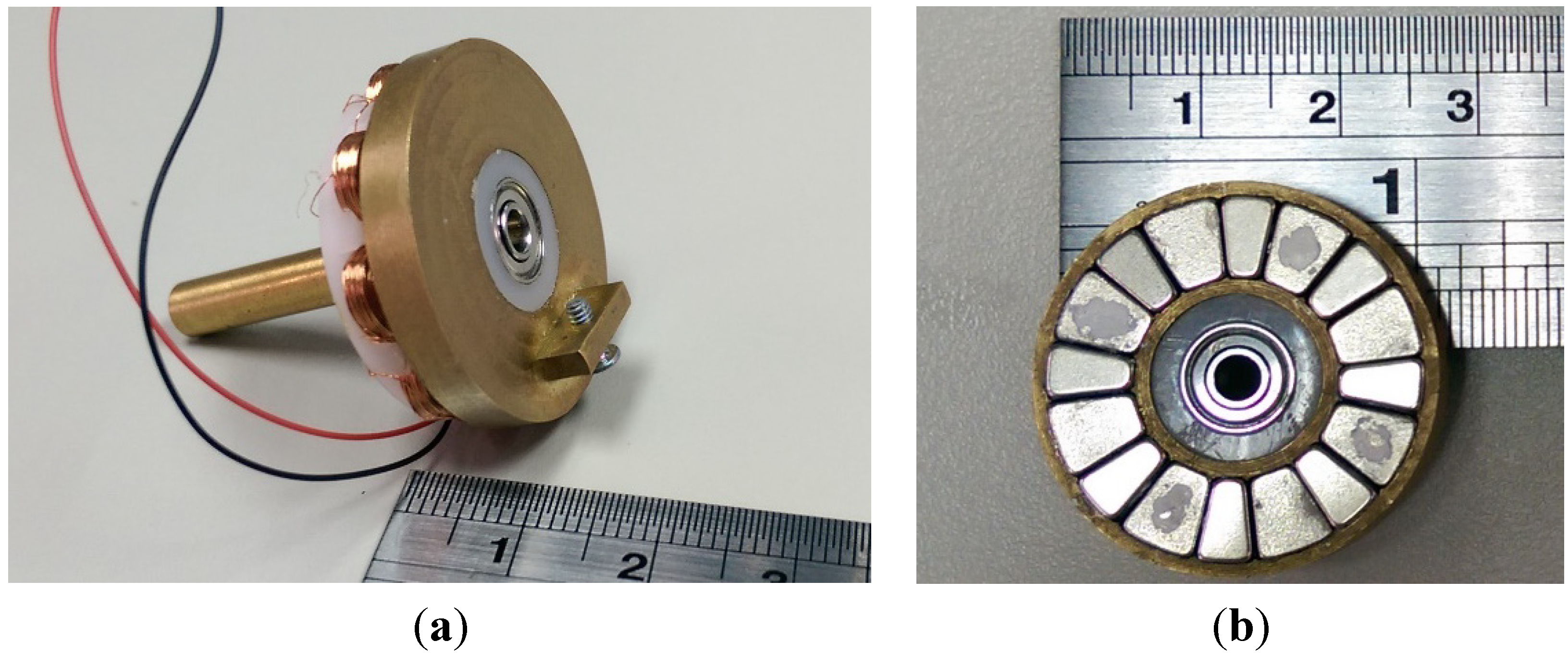
2.1. Weighted Rotor for Energy Harvester

Figure 1 shows the schematic diagram of the proposed weighted rotor, pivoted off-center on a wheel. Considering a fixed frame of reference oxy, the locations of the pivot and the wheel center are (x1, y1) and (x0, 0), respectively. The outer radius of the wheel is R1; the distance between the pivot of the weighted rotor and the wheel center is R2. The angular displacement, velocity, and acceleration of the wheel rotation are represented by α , α ˙ , and α ¨ , respectively. According to Wang et al. [17], the dynamic equation of a weighted rotor in a rotating wheel is written as:
θ ¨ + C T * θ ˙ + R 2 α ˙ 2 L * sinθ = α ¨ + a 0 L * cos ( θ α ) + R 2 α ¨ L * cosθ + g L * sin ( θ α )
where CT* is the generalized damping constant (including electromagnetic and mechanical damping), g is the gravitational acceleration, and a0 is the linear acceleration of the wheel center. The swing angle, angular velocity, and angular acceleration of the weighted rotor are represented by θ , θ ˙ , and θ ¨ , respectively. The characteristic length (L*) is expressed as:
L * = I M D
where I is the mass moment of inertia of the weighted rotor and MD is the product of the mass and the distance. The weighted rotor is composed of a rotor base, ball bearing, weighted block, adjustable screw, and magnets. I is the summation of mass moment of inertia of these parts. MD is the product of the mass of the weighted block and the adjustable screw (ma and mb), and the distance (da and db) between the pivot point of the weighted rotor and the center of mass of off-center parts, such as the weighted block and the adjustable screw, which are expressed as:
M D   = ( m a d a ) w e i g h t e d   b l o c k + ( m b d b ) a d j u s t a b l e   s c r e w
The position of the adjustable screw is allowed to be moved for fine adjusting L* when the other parameters are determined. Eight sets of pancake coils in a stator base are installed behind the magnets to induce a current and electromagnetic damping force. A ball bearing is mounted at the center of the stator base and is connected to the weighted rotor. A WREH is composed of a weighted rotor, magnets, and coil sets, as shown in Figure 2. Based on constant car speed ( α ¨ = 0 and a0 = 0), Equation (1) becomes:
θ ¨ + C T * θ ˙ + R 2 α ˙ 2 L * sinθ = g L * sin ( θ α )
Figure 1. Weighted rotor mounted on a rolling wheel.
Micromachines 06 00375 g001
Figure 2. Schematic diagram of WREH. (a) 3D schematic view of the WREH for TPMS. (b) Weighted rotor composed of magnets, a weighted block, and an adjustable screw.
Micromachines 06 00375 g002
The standard Runge–Kutta method is employed to obtain the dynamic behavior of the weighted rotor based on solving Equation (1). The listed parameters are decided in the following calculation: I = 1.725 × 10⁻⁶ kg·m2, g = 9.81 m/s2, and considering a 15-inch wheel to decide R1 = 0.300 m, R2 = 0.203 m. The characteristic length and generalized damping constant are 0.200 m and 1.15 N·s·kg−1·m−1, respectively, to simulate the time response of the WREH. Figure 3 shows the swing angle θ when the car speed is 50 km/h under the initial conditions θ ( 0 ) = 0 and θ ˙ (0) = 0.
θmax is the maximum swing angle defined according to the widest swing angle in one period. Equation (4) describes the dynamic behavior of the weighted rotor at a constant car speed. Linearized sinθ by θ in Equation (5), the natural frequency w n of the weighted rotor can be written as:
w n = α ˙ R 2 L *
Figure 3. Transient response of the swing angle at the car speed 50 km/h and initial conditions θ ( 0 ) = 0 and θ ˙ (0) = 0.
Micromachines 06 00375 g003
The requirement of L* = R2 causes the system to oscillate in resonance at any wheel speed [22]. Figure 4 shows the variation of the maximum angular speed of a WREH in a steady state at various characteristic lengths and wheel speeds with a total generalized damping constant of 1.10 N·s·kg−1·m−1. When the condition L* = R2 = 0.203 m is met, the angular speed varies continuously at wheel speeds from 200 to 1000 rpm. The maximum angular speed for L* > R2 is lower than that for L* = R2 at any wheel speed, meaning that the power generation is low. When L* << R2, such as L* = 0.198 m, the maximum angular speed exhibits a sudden discontinuous jump at a critical wheel rotation speed. When L* is close but slightly lower than R2, such as L* = 0.200 m, and the critical wheel speed is reached, the maximum angular speed decreases with the increment of wheel speed. The decreasing slope of the maximum angular speed for L* << R2 is higher than that for L* < R2 once the critical wheel speed is achieved. Therefore, the characteristic length L* of a WREH should be designed to be approximately equal to R2. In this case, a WREH with a characteristic length from 0.202 to 0.204 m is suitable at wheel speeds from 200 to 1000 rpm for energy harvesting.
Figure 4. Variation of the steady-state maximum angular speed of WREH with various L* and wheel speed with CT* = 1.10 N·s·kg−1·m−1.
Micromachines 06 00375 g004
In contrast to the previous discussion on constant wheel rotation speed, the following addresses two non-constant car velocity modes, acceleration and deceleration (Figure 5). Consider this example: The generalized damping constant is 0.5 N·s·kg−1·m−1, and the initial conditions are θ ( 0 ) = 0 and θ ˙ (0) = 0. The wheel rotation speed is represented by a yellow line shown in Figure 5. For the wheel radius of 0.300 m, the wheel rotation speed of 707 rpm is equal to the car speed of 80.2 km/h. As shown in Figure 5a, when the wheel angular acceleration speed is 73.7 rad/s2, the maximum swing angles of the three weighted rotors with different L* are close to those at the same constant wheel speed. Consider another example depicted in Figure 5b, when the high wheel angular acceleration speed of 148 rad/s2 to the same final speed 707 rpm, the weighted rotor with L* = 0.191 m demonstrates a jump phenomenon, but this does not occur for the other two L* (0.198 m and 0.203 m). The weighted rotors with L* close to R2 avoid the jump phenomenon even after a wheel angular acceleration is executed. The acceleration speed shown in Figure 5b is equal to that of a car accelerating from 22.6 to 80.2 km/h in 5 s, which represents the acceleration performance of a normal car on a highway. When a well-weighted rotor satisfies the requirement of L* = R2, the variation in maximum swing angle and maximum angular velocity is continuous, and no jump phenomenon occurs.
Figure 5. Maximum swing angle under various L*. (a) After angular acceleration of 73.7 rad/s2. (b) After angular acceleration of 148 rad/s2.
Micromachines 06 00375 g005

2.2. Output Voltage and Electromagnetic Damping

The induced electromotive force (EMF) ε for a coil in a magnetic field is expressed as:
ϵ = d φ d t = d φ d θ d θ d t
where φ is the magnetic flux. For an energy harvester series connected to an external load, the cross voltage (VL) on the external load is expressed as:
V L = ε R L R L + R C = d φ d θ d θ d t R L R L + R C
where RL and RC are the resistance of the external load and coil wires, respectively. The output (cross) voltage on the external load is measured using an oscilloscope and the angular velocity (dθ/dt) is calculated according to the rotor turns per second. In this case, RL = 550 Ω and RC = 85 Ω, based on Equations (6) and (7), the average value of dφ/dθ was calculated as 0.059 V·s in different angular velocity experiments. The value of RL is decided to make the damping constant approach to 1.10 N·s·kg−1·m−1. The torque Te caused by the electromagnetic damping to the weighted rotor can be expressed as:
T e = ( d φ / d θ ) 2 R c + R L θ ˙
Consequently, electromagnetic damping constant Ce* can be expressed as:
C e * = ( d φ / d θ ) 2 I ( R c + R L )

2.3. Optimization of Halbach Array Magnetic Circuit

The Halbach array is a periodic arrangement of magnets that augments the magnetic field on one side of the array where the coil sets rotate on, while cancelling the magnetic field on the other side. This magnetic field distribution improves the induced electromotive force [23]. Figure 6 shows the Halbach array concept arranged in a circular shape, with the red arrows representing the flux orientation of each magnet. The circular Halbach array disk is composed of 16 magnetic sector blocks and four periods in one circle.
Figure 6. Circular Halbach array magnetic disk.
Micromachines 06 00375 g006
There are four types of magnetization direction, two opposite axial (y-axis) directions, and two opposite tangential directions in one period, as shown in Figure 6. To pursue a high gradient of magnetic flux density for high power generation based on the same magnetic disk volume, the sector angles of the magnetic blocks should be optimized. In other words, the optimized sector-angle arrangement could achieve suitable electromagnetic damping value in the smallest magnetic disk. The sector-angle ratio rm as the parameter to be optimized is defined by the ration between the axial-direction sector angle a to the radial-direction sector angle b. Because the relative motion between the circular Halbach array disk and coil sets is on the xz plane, the y component of the magnetic flux density above the circular Halbach array disk should be analyzed. The coil rotation region is located between the inner and outer radius of the magnetic disk and is above the upper surface of the magnetic disk from 2 to 5 mm, as shown in Figure 7a. The magnetic field strength was calculated using COMSOL 4.2a software (COMSOL, Burlington, MA, USA) with a finite element module and the residual magnetism of each magnet set at 1.4 T. The relative permeability of the Neodymium-Iron-Boron (NdFeB) magnets and air are set at 1.05 and 1.00, respectively. The Y component of the magnetic flux density in the different altitudes from the upper surface of the magnetic disk to the altitude plane is shown in Figure 7b. Considering the uniform distribution of coil turns in each layer, the Y component of magnetic flux density for any rm in EMF calculation is determined according to the average value from the altitude planes of 2–5 mm (the thickness of the coil set), as shown in Figure 7c.
For power generation, the EMF based on the same coil parameters for different sector-angle ratios rm is applied as the objective function. The magnetic flux φ from each coil rotation in the xz plane is expressed as vt·D·[By·(Rc + D/2) − By·(RcD/2)], where vt, D, By, and Rc are the velocity of the coil, diameter of the coil, Y component of magnetic flux density, and position of the coil center, respectively. In the same layer, the diameter of each coil should be considered individually. Figure 8 shows the EMFs for different sector-angle ratios based on the same magnetic disk volume with an angular speed of 1 rps and the parameters listed in Table 1. The sector-angle ratios are plotted on logarithmic coordinates along the horizontal axis, and the sector angles are also indicated in Figure 8. A higher rm causes the circular Halbach array magnetic disk to approach the multipolar magnetic disk magnetized in tangential directions. Conversely, a lower rm causes the circular Halbach array magnetic disk as the multipolar magnetic disk magnetized in axial directions. The optimal rm for the largest EMF is located between the highest and the lowest rm. Moreover, rm = 1 is not the optimal design. As shown in Figure 8, rm = 19/26 provides the largest EMF as the optimal value of the sector-angle ratio for the circular Halbach array magnetic disk applied to the energy harvester for dimensions of the magnetic disk in this paper.
Figure 7. Simulations of the Y component of magnetic flux density. (a) The definition of the analyzed region. (b) The Y component of magnetic flux density for sector angle ratio (25/20) in different planes. (c) The average Y component of magnetic flux density for sector angle ratio (25/20).
Micromachines 06 00375 g007
Figure 8. Peak value of electromotive force for magnetic disks with different sector angle ratios rm.
Micromachines 06 00375 g008
Table 1. Parameters of the magnets and coils.
ParameterCircular Halbach Array Disk
Dimensions of individual magnetrout = 13.0 mm
rin = 7.0 mm
tm = 3.0 mm
Residual magnetism of magnet by axial magnetizationBr = 1.4 T
Coil wire diameterd = 0.1 mm
Coil turns in a layerNr = 20
Coil layers in a setNt = 30
Thickness of coil settc = 3.0 mm
Inside diameter of the coil setDin = 2.0 mm
Outside diameter of the coil setDout = 6.0 mm
Air gap between magnetic disk and coil setstp = 1.0 mm
Number of coil turn600

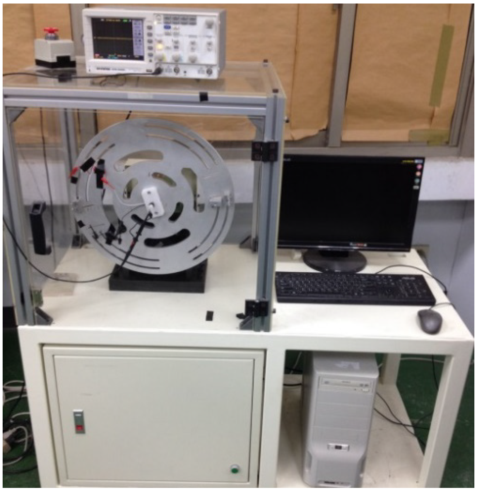
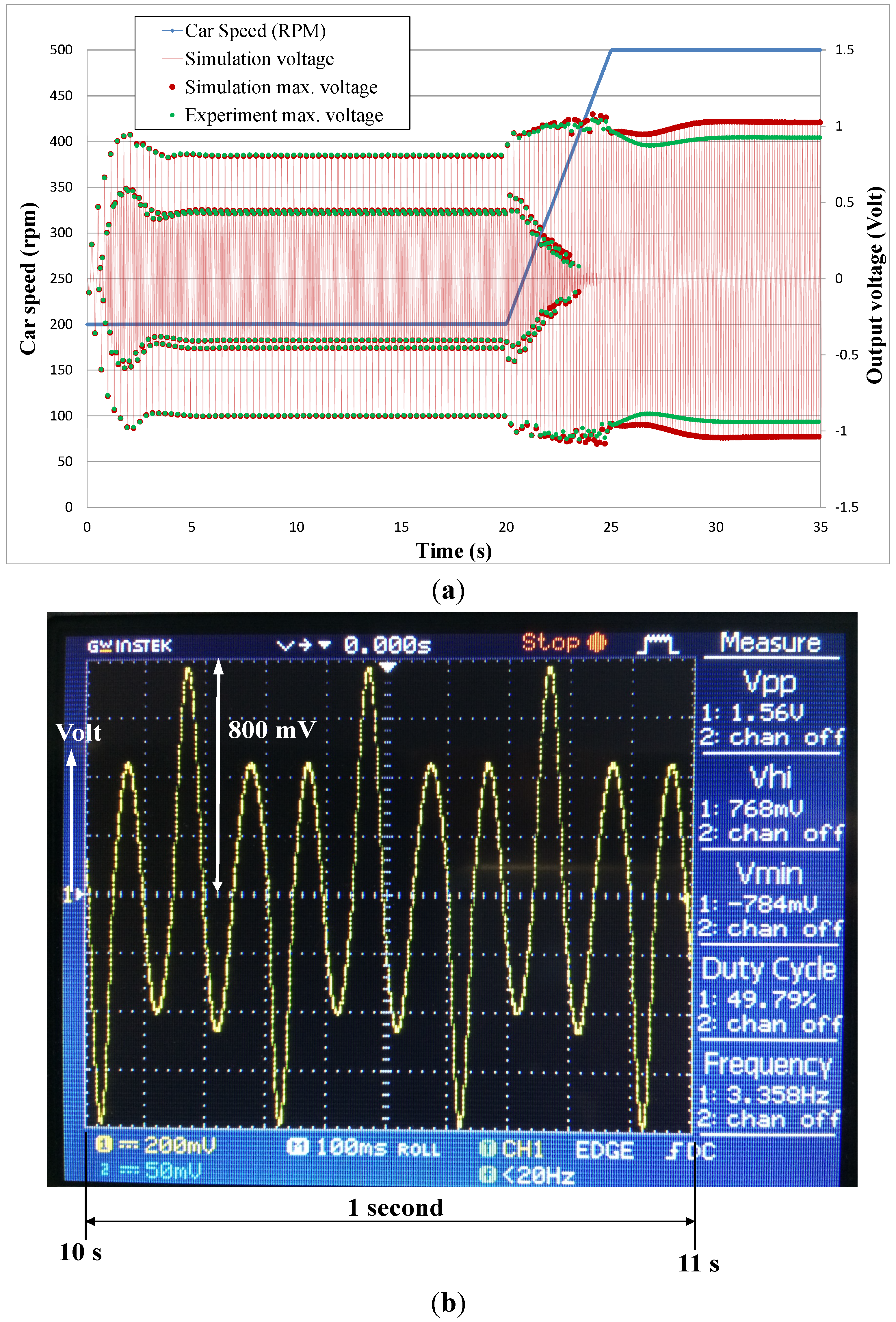
3. Experiments and Results

To verify the power generation and dynamic behavior of the energy harvester, a speed-controllable rotation plate was implemented, as shown in Figure 9. The rotation plate was driven by an AC servomotor connected to a motion-control card to set the rotation and acceleration speeds. A slip ring was mounted at the rotation center of the plate to connect the energy harvester to the oscilloscope used to measure the output voltage from the energy harvester.
Figure 10a shows a prototypical WREH that involves integrating the weighted rotor and the base with coil sets. The weighted rotor of the prototype is composed of brass, on which 16 NdFeB sector magnets are mounted rigidly, according to the optimum rm = 19/26, as shown in Figure 10b. The generalized damping includes electromagnetic and mechanical damping. The mechanical damping attributed to the ball bearing friction and air-dragging force disperses the energy and is unavoidable. The mechanical damping can be estimated by measuring the output voltage of a WREH in the open circuit in a steady state. For this prototype, the mechanical damping measured in the experiments was 0.20 N·s·kg−1·m−1. In the experiments, a 550 Ω external resistor was connected in series with the WREH. The voltage across the external resistor (VL) was measured as the experimental output voltage, using an oscilloscope. Figure 11a provides the instant output voltage results when the plate-rotation speed was accelerated from 200 to 500 rpm in 5 s, as indicated by the blue line. The maximum voltages of simulations and experiments are represented by red and green dots, respectively. When plate-rotation speeds were below 430 rpm, two additional small peaks appeared in the output voltage wave for one period, as shown in Figure 11b, which shows the voltage measurement from 10 to 11 s. This phenomenon is attributed to the swing angle of the weighted rotor being wider than the one period of the magnetic pole arrangement of 45°. An entire swing period of the weighted rotor is still the same as the plate-rotation period. Within the acceleration region from 20 to 25 s, both the simulation and experimental output voltage vary according to the plate-rotation speed and are accompanied by a transient response of 20–30 s. The differences between the simulation and experimental voltage at low plate-rotation speeds are smaller than those at high speeds.
Figure 9. Experiment setup for the energy harvester verification.
Micromachines 06 00375 g009
Figure 10. Prototype of the WREH with mass moment of inertia 1.725 × 10⁻⁶ kg·m2. (a) The weighted rotor assembled with the coil sets. (b) The circular Halbach array magnetic disk of sector angle ratio rm = 19/26.
Micromachines 06 00375 g010
Figure 11. Instant output voltage of the WREH from 200 to 500 rpm. (a) Simulation and experimental results. (b) Experimental output voltage of the WREH from 10 to 11 s.
Micromachines 06 00375 g011
The power generation from a WREH is the power consumed by the external resistor and is calculated using integration over an entire period from t0 to t1, the electromagnetic damping obtained from Equation (9) as well as the square of the angular velocity of the weighted rotor:
P = t 0 t 1 C e θ ˙ 2 d t R L R L + R C
Table 2 shows the average voltage and power generation from a WREH at various constant plate-rotation speeds. Both the numerical and experimental results demonstrate that the output power and the average voltage obtained from the energy harvester increased monotonically, with the plate-rotation speed contributing to the high angular velocity of the weighted rotor (dθ/dt), inducing a large EMF. With the increase of the plate-rotation speeds, the centrifugal force applying to the ball bearing also intensifies, thereby increasing the kinetic friction force that induces a high mechanical damping constant. Consequently, while the rotation plate was accelerating, the increasing rate of the output voltage in the experiments was lower than that in the simulations. The output voltage differences between the simulations and the experiments at high plate-rotation speeds are attributed to the large kinetic friction force.
Table 2. Output voltage and power at constant plate rotation speed.
Plate rotation speed (rpm)Average power generation simulation (μw)Average voltage simulation (V)Average power generation experiment (μw)Average voltage experiment (V)
3004040.4713990.468
3504540.4994450.494
4005070.5284910.520
4505550.5525260.538
5005850.5675350.541

4. Conclusions

This study proposes a WREH composed of a weighted rotor for use in TPMS applications considering the power generation. The numerical analysis and experimental results reveal that several hundred microwatts of output power are achievable for a WREH. If the characteristic length L* is equal to R2, then the natural frequency of a well-weighted rotor matches the rotation frequency of the car wheel. Consequently, resonance occurs at any wheel speed, and the well-weighted rotor demonstrates no jump phenomenon at either the constant or acceleration speeds of the rotation plate. To provide a suitable L*, the weighted condition can be fine-adjusted using the adjustable screw. The extremely high angular acceleration of the plate causes only a transient response within 2–5 s and does not affect the steady-state response of a well-weighted rotor. Therefore, oscillation at a wide angle and high angular velocity is feasible for generating high power. The mathematical model of output voltage and power generation employed in numerical simulation demonstrated favorable agreement with the experimental results. In the experiments, when the plate-rotation speed is 300–500 rpm—which is equal to normal car speeds of 33.9–59.5 km/h—the power generation of a WREH is between 399 and 535 μW. These results demonstrate that a WREH has the potential to be a power source for a TPMS.

Acknowledgments

The authors would like to thank the Ministry of Science and Technology for its financial support to the research (grant numbers 103-2218-E-110-009 and 103-2221-E-110-086).

Author Contributions

The original concept and models in research were provided by Yu-Jen Wang; he also wrote the paper, and supervised the work in all stages. The optimization of circular Halbach array magnetic disk and magnetic field strength were performed by Yu-Ti Hao. The model simulation and experiments were performed by Hao-Yu Lin.

Conflicts of Interest

The authors declare no conflict of interest.

References

  1. Roundy, S.; Leland, E.S.; Baker, J.; Carleton, E.; Reilly, E.; Lai, E.; Otis, B.; Rabaey, J.M.; Wright, P.K.; Sundararajan, V. Improving power output for vibration-based energy scavengers. IEEE Pervas. Comput. 2005, 4, 28–36. [Google Scholar] [CrossRef]
  2. Arnold, D.P. Review of microscale magnetic power generation. IEEE Trans. Magn. 2007, 43, 3940–3951. [Google Scholar] [CrossRef]
  3. Matsuzaki, R.; Todoroki, A. Wireless monitoring of automobile tires for intelligent tires. Sensors 2008, 8, 8123–8138. [Google Scholar] [CrossRef]
  4. Wang, Y.J.; Chen, C.D.; Lin, C.C.; Yu, J.H. A nonlinear suspended energy harvester for a tire pressure monitoring system. Micromachines 2015, 6, 312–327. [Google Scholar] [CrossRef]
  5. Schaijk, R.V.; Elfrink, R.; Oudenhoven, J.; Pop, V.; Wang, Z.; Renaud, M. A MEMS vibration energy harvester for automotive applications. Prco. SPIE 2013, 8763, 876305. [Google Scholar]
  6. Leland, E.S.; Wright, P.K. Resonance tuning of piezoelectric vibration energy scavenging generators using compressive axial preload. Smart Mater. Struct. 2006, 15, 1413–20. [Google Scholar] [CrossRef]
  7. Stanton, S.C.; McGehee, C.C.; Mann, B.P. Reversible hysteresis for broadband magnetopiezoelastic energy havesting. Appl. Phys. Lett. 2009, 95, 174103. [Google Scholar] [CrossRef]
  8. Sari, I.; Balkan, T.; Kulah, H. An electromagnetic micro power generator for wideband environmental vibrations. Sens. Actuators A 2008, 145–146, 405–413. [Google Scholar] [CrossRef]
  9. Lee, D.G.; Carman, G.P.; Murphy, D.; Schulenburg, C. Novel micro vibration energy harvesting device using frequency up conversion. In Proceeding of Sensors Solid-State Actuators and Microsystems Conference Transducers, Lyon, French, 10–14 June 2007.
  10. Daminakis, M.; Goethals, J.; Kowtke, J. Enhancing power harvesting using a tuned auxiliary structure. J. Intell. Mater. Syst. Struct. 2005, 16, 825–834. [Google Scholar] [CrossRef]
  11. Spreemann, D.; Manoli, Y.; Folkmer, B.; Mintenbeck, D. Non-resonant vibration conversion. J. Micromech. Microeng. 2006, 16, 169–173. [Google Scholar] [CrossRef]
  12. Wang, Y.J.; Chen, C.D.; Sung, C.K. Design of a frequency-adjusting device for harvesting energy from a rotating wheel. Sens. Actuators A 2010, 159, 196–203. [Google Scholar] [CrossRef]
  13. Guizzi, G.L.; Mannon, M.; Manzi, G.; Salvatori, M. Preliminary study on a kinetic energy recovery system for sailing yachts. Renew. Energy 2014, 62, 216–225. [Google Scholar] [CrossRef] [Green Version]
  14. Lu, C.H.; Wang, Y.J.; Sung, C.K.; Chao, P.C.P. A hula-hoop energy-harvesting system. IEEE Trans. Magn. 2011, 47, 2395–2398. [Google Scholar] [CrossRef]
  15. Barton, D.A.W.; Burrow, S.G.; Clare, L.R. Energy harvesting from vibrations with a nonlinear oscillator. J. Vib. Acoustics 2010, 132, 021009. [Google Scholar] [CrossRef]
  16. Singh, K.B.; Bedekar, V.; Taheri, S.; Priya, S. Piezoelectric vibration energy harvesting system with an adaptive frequency tuning mechanism for intelligent tires. Mechatronics 2012, 22, 970–988. [Google Scholar] [CrossRef]
  17. Wang, Y.J.; Chen, C.D.; Sung, C.K. System design of a weighted-rotor type electromagnetic generator for harvesting energy from a rotating wheel. IEEE/ASME Trans. Mechatron. 2013, 18, 754–763. [Google Scholar] [CrossRef]
  18. Wu, X.; Parmar, M.; Lee, D.W. A seesaw-structured energy harvester with super wide bandwidth for TPMS application. IEEE/ASME Trans. Mechatron. 2013, 19, 1514–1522. [Google Scholar]
  19. Manla, G.; White, N.M.; Tudor, M.J. Numerical model of a non-contact piezoelectric energy harvester for rotating objects. IEEE Sens. J. 2011, 12, 1785–1793. [Google Scholar] [CrossRef]
  20. Lee, J.; Choi, B. Development of a piezoelectric energy harvesting system for implementing wireless sensors on the tires. Energy Convers. Manag. 2014, 78, 32–38. [Google Scholar] [CrossRef]
  21. Introduction of TPMS. Orange Electronic. Available online: http://www.orange-electronic.com (accessed on 19 March 2015).
  22. Wang, Y.J.; Chen, C.D. Design and jump phenomenon analysis of an eccentric ring energy harvester. Smart Mater. Struct. 2013, 22, 105019. [Google Scholar] [CrossRef]
  23. Wang, Y.J.; Chen, C.D.; Sung, C.K.; Li, C. Natural frequency self-tuning energy harvester using a circular Halbach array magnetic disk. J. Intell. Mater. Syst. Struct. 2012, 23, 933–943. [Google Scholar] [CrossRef]

