Wide Linearity Range and Highly Sensitive MEMS-Based Micro-Fluxgate Sensor with Double-Layer Magnetic Core Made of Fe–Co–B Amorphous Alloy

Abstract
:1. Introduction
2. Materials and Methods
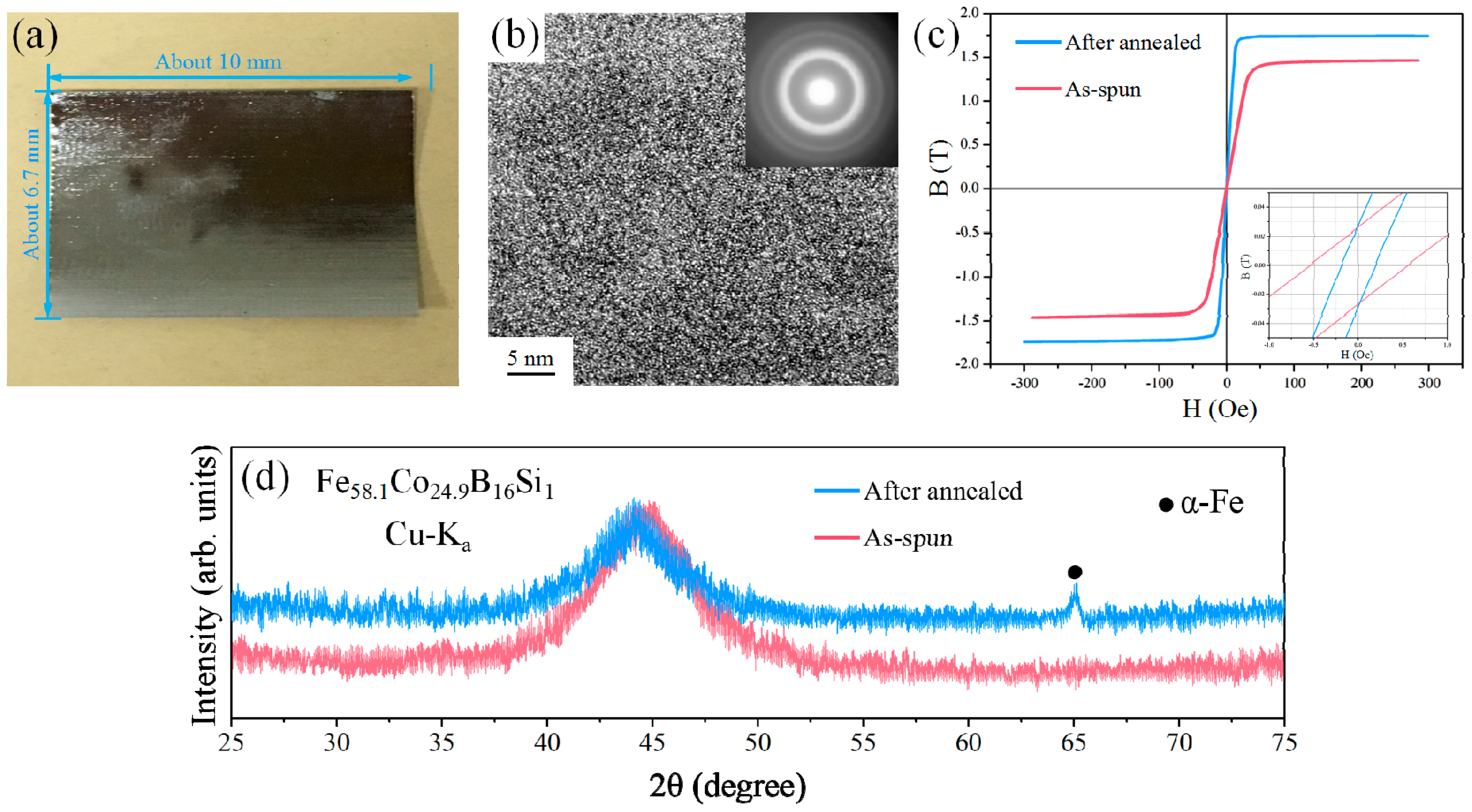
2.1. Preparation of the Fe58.1Co24.9B16Si1 Amorphous Alloy
2.2. Fabrication of the Micro-Fluxgate Sensor
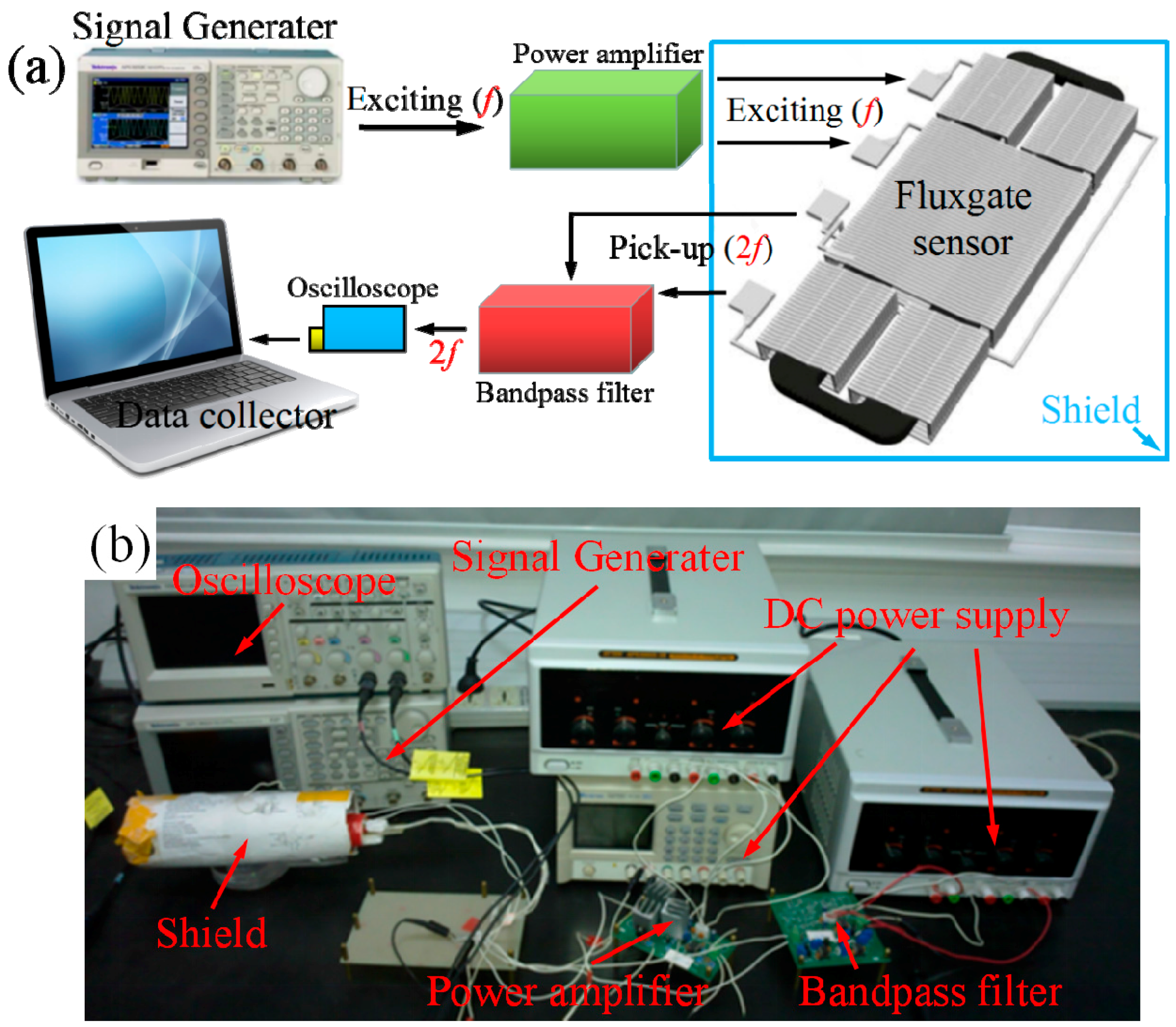
2.3. Testing System of the Micro-Fluxgate Sensor
3. Results and Discussion
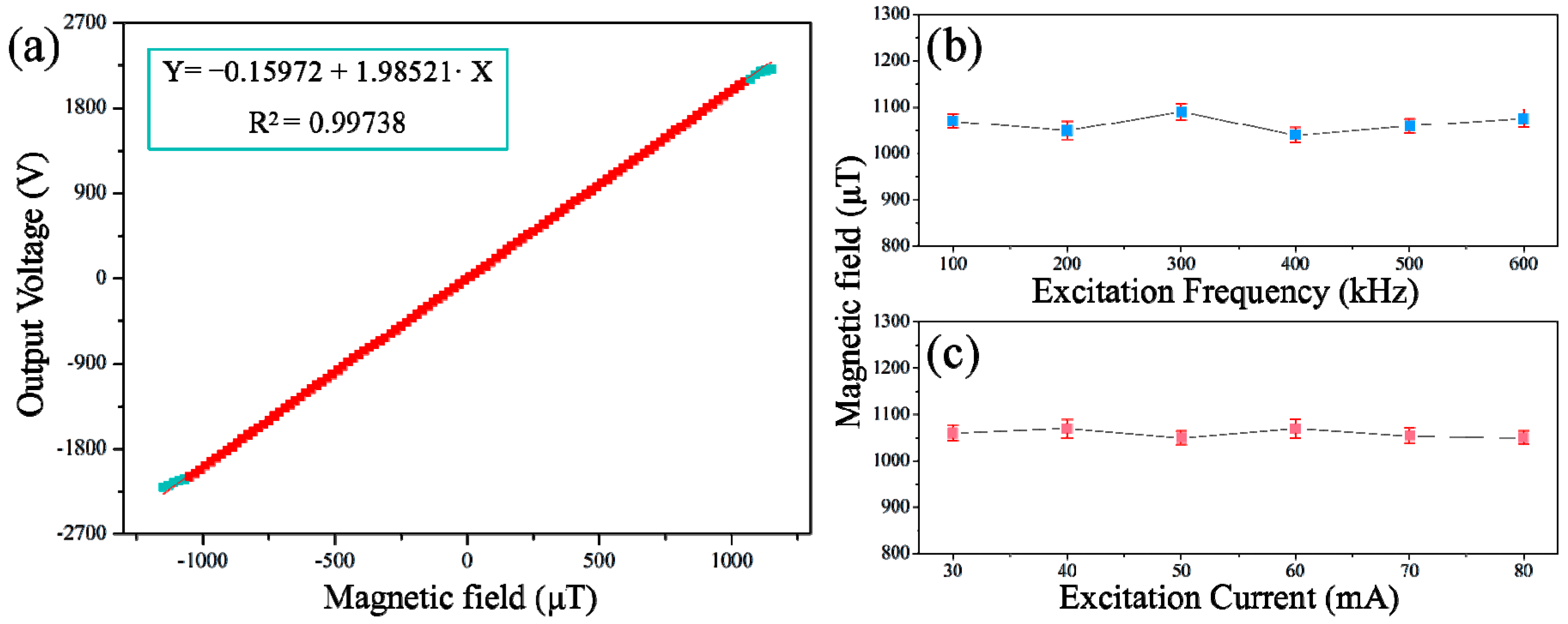
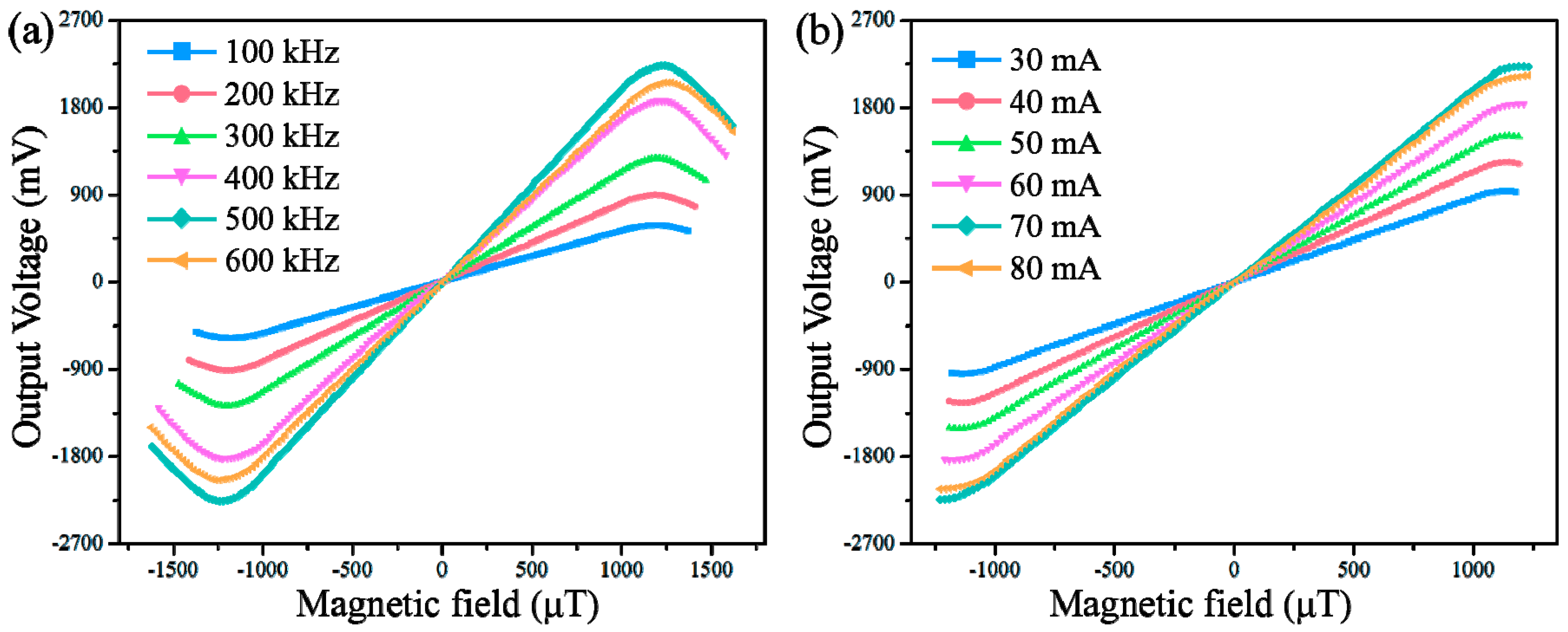
3.1. Sensitivity and Linearity
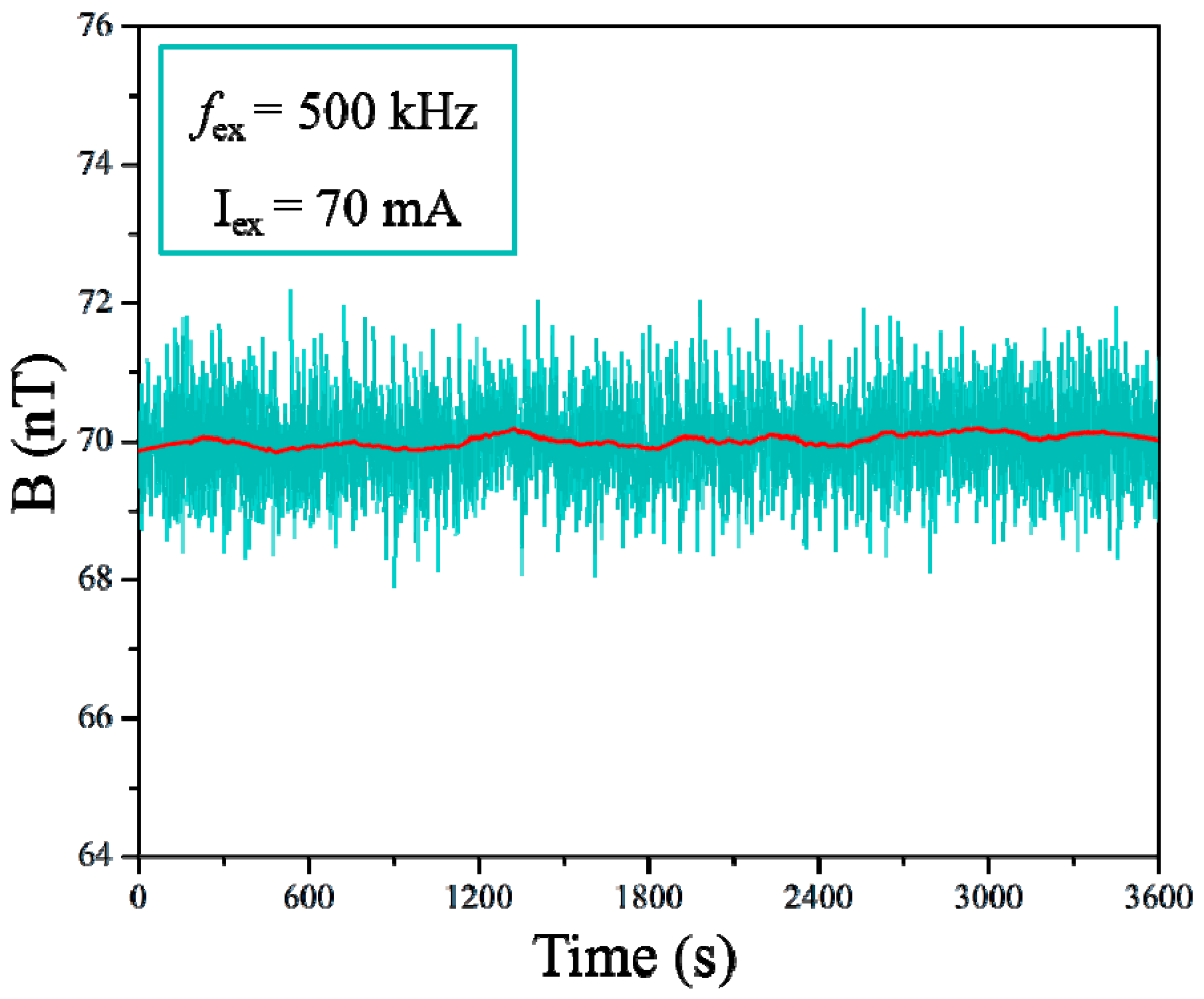
3.2. Offset Stability
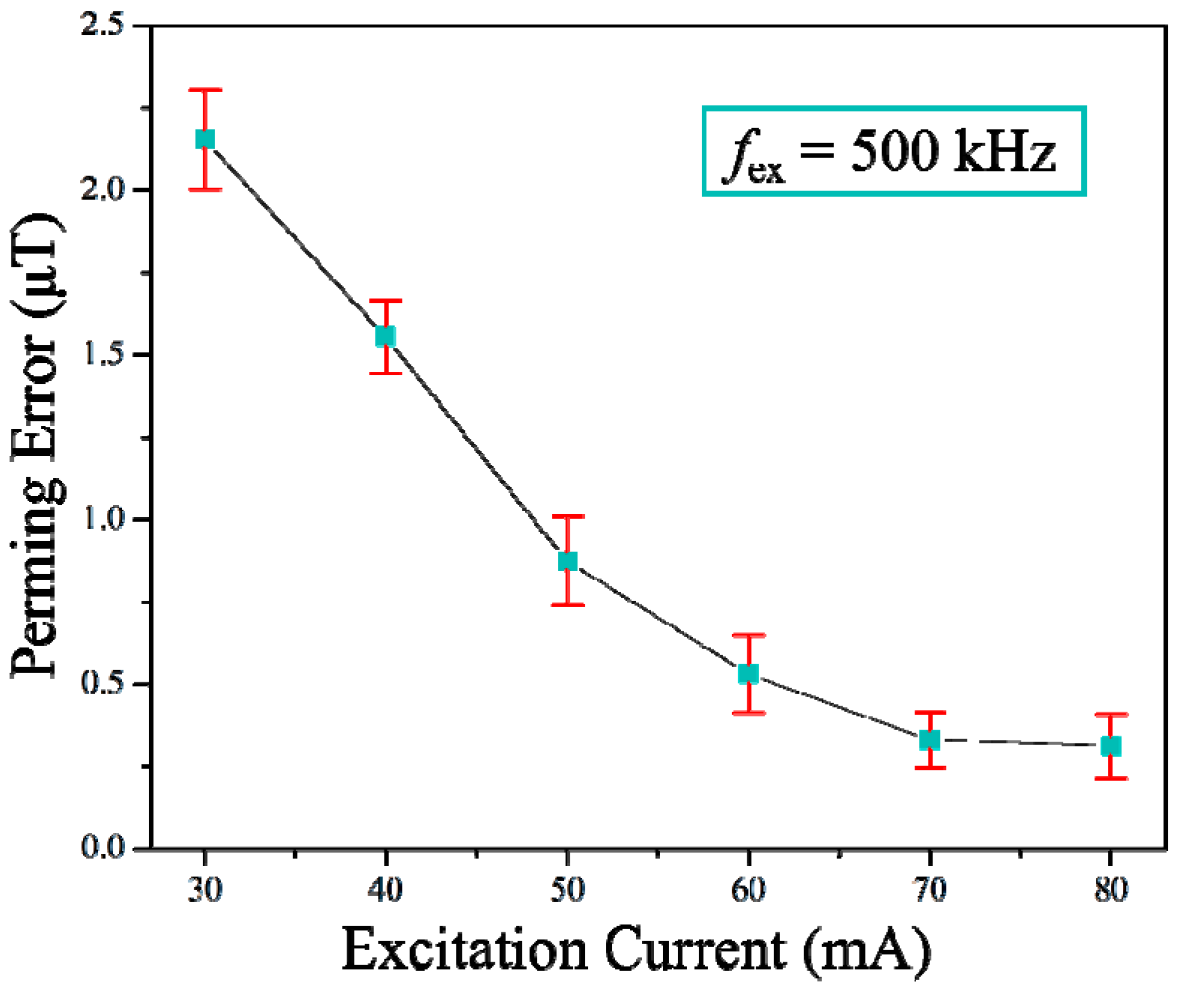
3.3. Perming Error
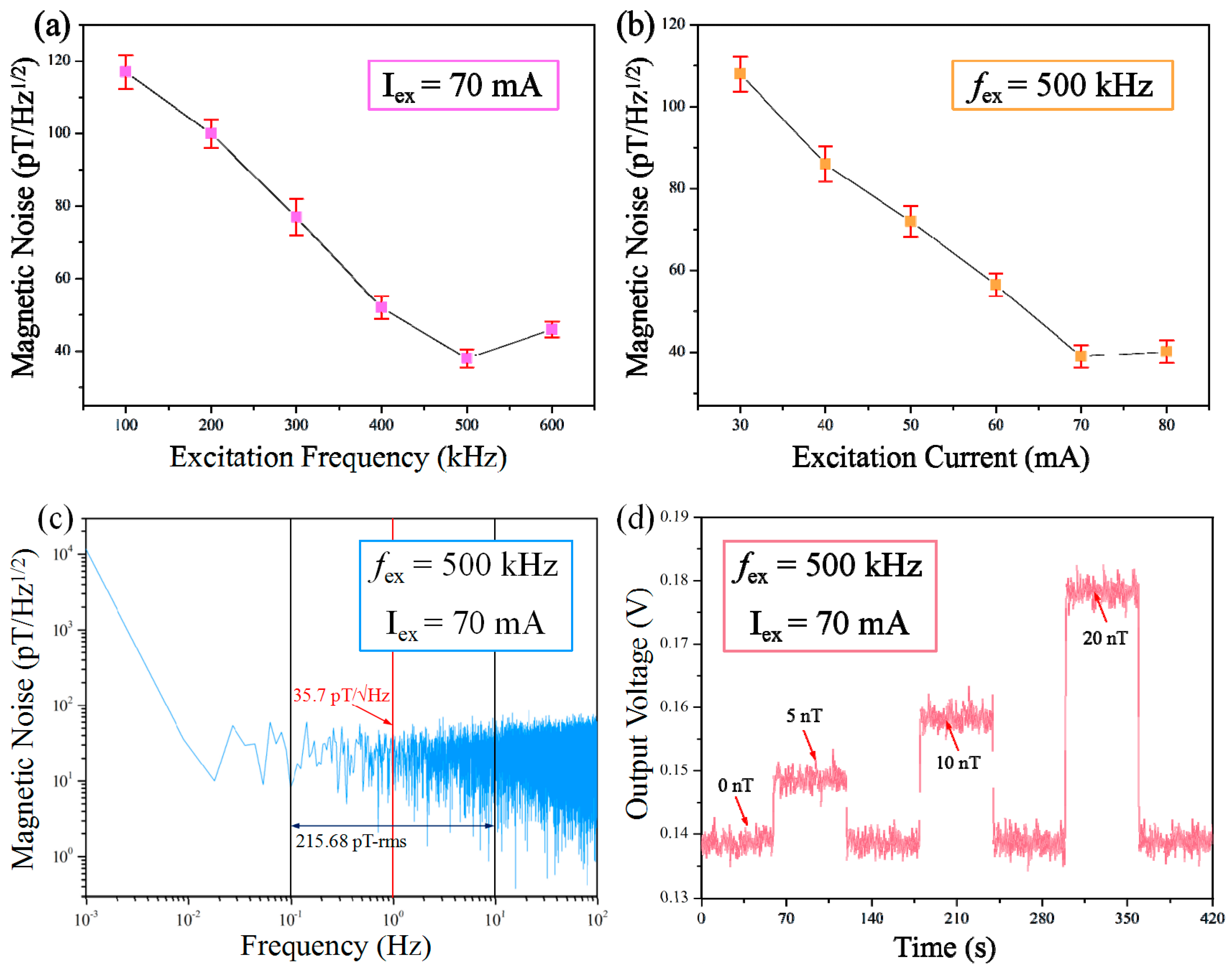
3.4. Noise
4. Conclusions
Supplementary Materials
Acknowledgments
Author Contributions
Conflicts of Interest
References
- Liakopoulos, T.M.; Chong, H.A. A micro-fluxgate magnetic sensor using micromachined planar solenoid coils. Sens. Actuators A Phys. 1999, 77, 66–72. [Google Scholar] [CrossRef]
- Kubik, J.; Pavel, L.; Ripka, P. PCB racetrack fluxgate sensor with improved temperature stability. Sens. Actuators A Phys. 2006, 130, 184–188. [Google Scholar] [CrossRef]
- Trigona, C.; Sinatra, V.; Andò, B.; Baglio, S.; Bulsara, A.R. Flexible microwire residence times difference fluxgate magnetometer. IEEE Trans. Instrum. Meas. 2017, 66, 559–568. [Google Scholar] [CrossRef]
- Khawaja, A.H.; Huang, Q.; Li, J.; Zhang, Z. Estimation of current and sag in overhead power transmission lines with optimized magnetic field sensor array placement. IEEE Trans. Magn. 2017, 53, 1–10. [Google Scholar] [CrossRef]
- Snoeij, M.F.; Schaffer, V.; Udayashankar, S.; Ivanov, M.V. Integrated fluxgate magnetometer for use in isolated current sensing. IEEE J. Solid-State Circuits 2016, 51, 1684–1694. [Google Scholar] [CrossRef]
- Miles, D.M.; Mann, I.R.; Ciurzynski, M.; Barona, D.; Narod, B.B.; Bennest, J.R.; Cupido, C. A miniature, low-power scientific fluxgate magnetometer: A stepping-stone to cube-satellite constellation missions. J. Geophys. Res. Space Phys. 2016, 121, 12–15. [Google Scholar] [CrossRef]
- Lu, C.C.; Huang, J.; Po-Kai, C.; Shih-Liang, C.; Jen-Tzong, J. High-sensitivity low-noise miniature fluxgate magnetometers using a flip chip conceptual design. Sensors 2014, 14, 13815–13829. [Google Scholar] [CrossRef] [PubMed]
- Lei, C.; Wang, R.; Zhou, Y.; Zhou, Z. MEMS micro fluxgate sensors with mutual vertical excitation coils and detection coils. Microsyst. Technol. 2009, 15, 969–972. [Google Scholar] [CrossRef]
- Kirchhoff, M.R.; Büttgenbach, S. MEMS fluxgate magnetometer for parallel robot application. Microsyst. Technol. 2010, 16, 787–790. [Google Scholar] [CrossRef]
- Díaz-Michelena, M. Small magnetic sensors for space applications. Sensors 2009, 9, 2271–2288. [Google Scholar] [CrossRef] [PubMed]
- Ripka, P. Advances in fluxgate sensors. Sens. Actuators A Phys. 2003, 106, 8–14. [Google Scholar] [CrossRef]
- Lei, J.; Wang, T.; Lei, C.; Zhou, Y. Detection of dynabeads using a micro-electro-mechanical-systems fluxgate sensor. Appl. Phys. Lett. 2013, 102, 166–170. [Google Scholar] [CrossRef]
- Grejner-Brzezinska, D.A.; Toth, C.K.; Moore, T.; Raquet, J.F.; Miller, M.M.; Kealy, A. Multisensor navigation systems: A remedy for GNSS vulnerabilities? Proc. IEEE 2016, 104, 1339–1353. [Google Scholar] [CrossRef]
- Zorlu, O.; Kejik, P.; Popovic, R.S. An orthogonal fluxgate-type magnetic microsensor with electroplated permalloy core. Sens. Actuators A Phys. 2007, 135, 43–49. [Google Scholar] [CrossRef]
- Andd, B.; Baelio, S.; Sacco, V.; Bulsara, A. Noise effects in RTD-fluxgate. IEEE Conf. Sens. 2005, 4, 935–938. [Google Scholar]
- Butta, M.; Sasada, I. Orthogonal fluxgate with annealed wire core. IEEE Trans. Magn. 2013, 49, 62–65. [Google Scholar] [CrossRef]
- Hasegawa, R. Advances in amorphous and nanocrystalline magnetic materials. J. Magn. Magn. Mater. 2006, 304, 187–191. [Google Scholar] [CrossRef]
- Wang, F.; Inoue, A.; Han, Y. Excellent soft magnetic Fe-Co-B-based amorphous alloys with extremely high saturation magnetization above 1.85 T and low coercivity below 3 A/m. J. Alloys Compd. 2017, 711, 132–142. [Google Scholar] [CrossRef]
- Kohmoto, O.; Ohya, K.; Yamaguchi, N.; Fujishima, H.; Ojima, T. Magnetic properties of zero magnetostrictive amorphous Fe-Co-Si-B alloys. J. Appl. Phys. 1979, 50, 5054–5056. [Google Scholar] [CrossRef]
- Vasquez, M.; Ascasibar, E.; Hernando, A.; Nielsen, O.V. Co-Si-B and Fe-Co-B amorphous alloys: Induced anisotropy and various magnetic properties. J. Magn. Magn. Mater. 1987, 66, 37–44. [Google Scholar] [CrossRef]
- Chen, L.H.; Klemmer, T.J.; Ellis, K.A.; Dover, R.B.; Jin, S. Soft-magnetic properties of Fe-Co-B thin films for ultra-high-frequency applications. J. Appl. Phys. 2000, 87, 5858–5860. [Google Scholar] [CrossRef]
- Li, X.P.; Fan, J.; Ding, J.; Chiriac, H.; Qian, X.B.; Yi, J.B. A design of orthogonal fluxgate sensor. J. Appl. Phys. 2006, 99, 08B313. [Google Scholar] [CrossRef]
- Jie, F.; Ning, N.; Ji, W.; Chiriac, H.; Xiaoping, L. Study of the noise in multicore orthogonal fluxgate sensors based on Ni-Fe/Cu composite microwire arrays. IEEE Trans. Magn. 2009, 45, 4451–4454. [Google Scholar]
- Ripka, P.; Butta, M.; Jie, F.; Li, X. Sensitivity and noise of wire-core transverse fluxgate. IEEE Trans. Magn. 2010, 46, 654–657. [Google Scholar] [CrossRef]
- Han, Y.; Inoue, A.; Kong, F.L.; Chang, C.T.; Shu, S.L.; Shalaan, E.; Al-Marzouki, F. Softening and good ductility for nanocrystal-dispersed amorphous Fe-Co-B alloys with high saturation magnetization above 1.7 T. J. Alloys Compd. 2016, 657, 237–245. [Google Scholar] [CrossRef]
- Makino, A.; Men, H.; Kubota, T.; Yubuta, K.; Inoue, A. FeSiBPCu nanocrystalline soft magnetic alloys with high Bs, of 1.9 tesla produced by crystallizing hetero-amorphous phase. Mater. Trans. 2009, 50, 204–209. [Google Scholar] [CrossRef]
- Wang, F.; Inoue, A.; Han, Y.; Zhu, S.L.; Kong, F.L.; Zanaeva, E. Soft magnetic Fe-Co-based amorphous alloys with extremely high saturation magnetization exceeding 1.9 T and low coercivity of 2 A/m. J. Alloys Compd. 2017, 723, 376–384. [Google Scholar] [CrossRef]
- Garcia, A.; Moron, C. Biaxial magnetometer sensor. IEEE Trans. Magn. 2002, 38, 3312–3314. [Google Scholar] [CrossRef]
- Lei, J.; Lei, C.; Zhou, Y. Analysis and comparison of the performance of MEMS fluxgate sensors with permalloy magnetic cores of different structures. Measurement 2013, 46, 710–715. [Google Scholar] [CrossRef]
- Malátek, M.; Kraus, L. Off-diagonal GMI sensor with stress-annealed amorphous ribbon. Sens. Actuators A Phys. 2010, 164, 41–45. [Google Scholar] [CrossRef]
- Marauska, S.; Jahns, R.; Kirchhof, C.; Claus, M.; Quandt, E.; Knöchel, R.; Wagner, B. Highly sensitive wafer-level packaged MEMS magnetic field sensor based on magnetoelectric composites. Sens. Actuators A Phys. 2013, 189, 321–327. [Google Scholar] [CrossRef]
- Kachniarz, M.; Petruk, O.; Salach, J. Functional properties of monolayer and bilayer graphene hall-effect sensors. Acta Phys. Pol. A 2017, 5, 1250–1254. [Google Scholar] [CrossRef]
- AICHI Micro Intelligent Co. Commercialized GMI Sensor (Type DH). Available online: https://www.aichi-mi.com/e-home-new/highly-sensitive-magnetometers/type-dh/ (accessed on 17 November 2017).
- HoneyWell Co. Commercialized HMR Sensor (Type HMR 3300). Available online: https://www.digikey.com.cn/product-detail/zh/honeywell-microelectronics-precision-sensors/HMR3300/342-1032-ND/396917 (accessed on 17 November 2017).
- HoneyWell Co. Commercialized HMR Sensor (Type HMR2300-D21–485). Available online: https://www.digikey.com.cn/product-detail/zh/honeywell-microelectronics-precision-sensors/HMR2300-D21-485/342-1019-ND/334174 (accessed on 17 November 2017).
- MEDA Co. Commercialized Fluxgate Sensor (Type μMag-01/02). Available online: http://www.meda.com/umag.htm (accessed on 17 November 2017).
- Bartington Co. Commercialized Fluxgate Sensor (Type Mag619). Available online: http://www.bartington.com/presentation/mag619-miniature-fluxgate-probe (accessed on 17 November 2017).
- Dowaytech Co. Commercialized TMR Sensor (Type TMR9003). Available online: http://www.dowaytech.com/1886.html (accessed on 17 November 2017).
- Snoeij, M.F.; Schaffer, V.; Udayashankar, S.; Ivanov, M.V. An integrated fluxgate magnetometer for use in closed-loop/open-loop isolated current sensing. In Proceedings of the ESSCIRC Conference 2015-41st European Solid-State Circuits Conference (ESSCIRC), Graz, Austria, 14–18 September 2015; pp. 263–266. [Google Scholar]
- Yang, X.; Li, Y.; Zheng, W.; Guo, W.; Wang, Y.; Yan, R. Design and realization of a novel compact fluxgate current sensor. IEEE Trans. Magn. 2015, 51, 1–4. [Google Scholar] [CrossRef]


| Materials, Methods | Linearity Ranges | Sensitivity (V/T) | Size | Resolution | Noise Level | Operating Current | Reference |
|---|---|---|---|---|---|---|---|
| Permalloy-based MEMS-micro-fluxgate sensor | ±300 μT | 327 | 3 × 4 mm2 | -- | -- | 150 mA | [29] |
| Co-based amorphous ribbon fluxgate sensor | ±1 mT | 593 | 3 × 6.5 cm2 | -- | 790 pT/Hz1/2 | 600 mA | [7] |
| Co-based amorphous ribbon giant magnetoimpedance (GMI) sensor | ~±1 μT | ~1800 | 1 × 9 mm2 | -- | 17 pT/Hz1/2 | 20 mA | [30] |
| Magnetoelectric composite-based sensor | ~1 nT–1 μT | 3800 | 4 × 4 mm2 | -- | 27 pT/Hz1/2 | -- | [31] |
| Hall sensor based on bilayer graphene | ±8 mT | 32 | 0.7 × 2.1 mm2 | 118 μT | -- | 1.2 mA | [32] |
| Commercialized GMI sensor (Type DH) by AICHI micro intelligent Co., Ltd., Tōkai, Japan | ±40 μT | 106 | 35 × 11 mm2 | 1 nT | 30 pT/Hz1/2 | 15 mA | [33] |
| Commercialized HMR sensor (Type 3300) by HoneyWell Co., Ltd., Seoul, Korea | ±200 μT | -- | 82 × 38 mm2 | 10 nT | -- | 35 mA | [34] |
| Commercialized HMR sensor (Type 2300-D21-485) by HoneyWell Co., Ltd., Seoul, Korea | ±40 μT | -- | 25 × 30 mm2 | 6.7 nT | -- | 27 mA | [35] |
| Commercialized Fluxgate sensor (Type uMag-01/02) by MEDA Co., Ltd., Tianjin, China | ±2 μT~±200 μT | -- | 12 × 27 mm2 | 1 nT | -- | -- | [36] |
| Commercialized Fluxgate sensor (Type Mag619) by Bartington Co., Ltd., Witney, UK | ±60 μT | -- | 25 × 20 mm2 | Several nT | ≤50 pT/Hz1/2 | 38 mA | [37] |
| Commercialized TMR sensor (Type TMR9003) by Dowaytech Co., Ltd., San Jose, CA, USA | ±1.5 mT | 300 | 6 × 5 mm2 | -- | 750 pT/Hz1/2 | 20 μA | [38] |
| This work | ±1.05 mT | 1985 | 2.7 × 7.3 mm2 | 5 nT | 36 pT/Hz1/2 | 70 mA | Current study |
© 2017 by the authors. Licensee MDPI, Basel, Switzerland. This article is an open access article distributed under the terms and conditions of the Creative Commons Attribution (CC BY) license (http://creativecommons.org/licenses/by/4.0/).
Share and Cite
Guo, L.; Wang, C.; Zhi, S.; Feng, Z.; Lei, C.; Zhou, Y. Wide Linearity Range and Highly Sensitive MEMS-Based Micro-Fluxgate Sensor with Double-Layer Magnetic Core Made of Fe–Co–B Amorphous Alloy. Micromachines 2017, 8, 352. https://doi.org/10.3390/mi8120352
Guo L, Wang C, Zhi S, Feng Z, Lei C, Zhou Y. Wide Linearity Range and Highly Sensitive MEMS-Based Micro-Fluxgate Sensor with Double-Layer Magnetic Core Made of Fe–Co–B Amorphous Alloy. Micromachines. 2017; 8(12):352. https://doi.org/10.3390/mi8120352
Chicago/Turabian StyleGuo, Lei, Cai Wang, Saotao Zhi, Zhu Feng, Chong Lei, and Yong Zhou. 2017. "Wide Linearity Range and Highly Sensitive MEMS-Based Micro-Fluxgate Sensor with Double-Layer Magnetic Core Made of Fe–Co–B Amorphous Alloy" Micromachines 8, no. 12: 352. https://doi.org/10.3390/mi8120352