Development of Highly Nano-Dispersed NiO/GDC Catalysts from Ion Exchange Resin Templates
by
 , ,
, ,
Angel Caravaca
1,2,* ,
,
Sebastien Picart
3,
Mimoun Aouine
2,
Benedicte Arab-Chapelet
1,
Philippe Vernoux
2 and
Thibaud Delahaye
1,* 1
CEA, DEN, DMRC/SFMA/LPCA, F-30207 Bagnols-sur-Cèze CEDEX, France
2
Université de Lyon, CNRS, Université Claude Bernard Lyon 1, IRCELYON, UMR 5256, 2 Avenue A. Einstein, 69626 Villeurbanne, France
3
CEA, DEN/DMRC/CETAMA, F-30207 Bagnols-sur-Cèze CEDEX, France
*
Authors to whom correspondence should be addressed.
Catalysts 2017, 7(12), 368; https://doi.org/10.3390/catal7120368
Submission received: 7 November 2017
/
Revised: 20 November 2017
/
Accepted: 20 November 2017
/
Published: 28 November 2017
Abstract
:Novel NiO/GDC (Gadolinium-doped Ceria) cermet catalysts were developed by the Weak Acid Resin (WAR) method using an ion exchange resin template. In addition, the specific surface area of these tunable materials was enhanced by NiO partial dissolution in aqueous acid solution. The whole procedure highly improved the micro-structural properties of these materials compared to previous studies. Catalysts with high metal loadings (≥10%), small Ni nanoparticles (<10 nm), and high specific surface areas (>70 m2/g) were achieved. These properties are promising for catalytic applications such as methane steam reforming for H2 production.
1. Introduction
Even though carbon-based materials (mainly activated carbon, graphite, and carbon nanofibers) exhibit an interesting performance as catalytic supports in other catalytic processes, one of the major deactivation factors of Ni catalysts in methane reforming processes is the deposition of carbonaceous species [1]. In this sense, several approaches have been developed to overcome the problem of carbon deposition.
Carbon deposition is structure-sensitive in nature and the particle size of Ni has an important role in the steam reforming of methane. Large and aggregated particles of nickel have a lower proportion of surface-exposed Ni atoms, and are therefore more vulnerable to the deposition of various carbon species. By contrast, Ni small nanoparticles provide a large metal active surface area and hence improved catalytic activity [2,3].
On the other hand, the extent of interaction between Ni active sites and the support play a very important role. Recently, Huang et al. demonstrated that, using Gadolinia-Doped Ceria (GDC) as catalytic support, the supported Ni catalyst may have a self-de-coking ability (at temperatures higher than 600 °C). This way, the deposited carbon species would be removed by their oxidation with the O2− species supplied from the lattice of the catalyst support [4,5,6,7,8].
However, according to the above-mentioned studies, conventional wet impregnation of Ni precursors over GDC leads to a poor dispersion of Ni. This synthesis procedure results in Ni/GDC catalysts with large and aggregated Ni particles (~30 nm) and limited specific surface area (20–45 m2 g−1 after calcination at temperatures lower than 750 °C) when high loadings are required (>3% Ni w/w). The improvement of these structural properties will clearly enhance the activity of these catalysts.
Here we report, for the first time, a new synthesis procedure for the preparation of novel NiO/GDC catalysts, aimed at the production of materials with highly dispersed/small Ni nanoparticles and high specific surface area, even when the Ni loadings are higher than 5 wt % (as is usually the case in methane reforming processes). The synthesis is based on a modified Weak Acid Resin method [9,10] (Supplementary Materials, Section 1.2), following a procedure explained in the Experimental section. This is the first time in the literature that the WAR method is used for a catalytic purpose.
2. Results and Discussion
The first series of 6 different Ni/GDC catalysts were prepared by the WAR method (Supplementary Materials, Section 1.2). All starting solutions were prepared with a Ce/Gd molar ratio ~4 (Ce0.8Gd0.2O2-δ). In addition, the concentration of Ni in the starting solutions varied from 0 to 100 mol %. Samples were named as follows: GDC, NiGDC X (X = 25, 50, 75, 90, where X = mol % Ni in starting solution), and 100 Ni (100% Ni).
Figure 1a shows the molar concentration of Ni in the catalysts obtained after the calcination of the metal loaded resin. First, the solid materials were dissolved and analyzed via ICP-AES (Inductively coupled plasma atomic emission spectroscopy) For comparison, both the starting (Before Exchange, BE) and the final solutions (After Exchange, AE) were analyzed by ICP-AES, and the Ni, Ce, and Gd loadings in the catalyst were calculated by subtraction (Supplementary Materials, Section 1.3). It can be clearly observed that the catalyst compositions obtained by both methods are consistent. In addition, Figure 1b shows that the Ce/Gd molar ratio in the catalysts was very similar to that of the initial solution (Ce/Gd ~ 3–4), while the Ni concentration was lower. This indicates that the affinity of the resin for the ionic exchange was similar for both lanthanides (Ce3+ and Gd3+) and lower for Ni2+, since the electrostatic effects are predominant and, as a consequence, the ion exchanger prefers the counter-ion of higher valence [11].
The thermal conversion of the metal loaded resin was investigated using TGA (Thermogravimetric analysis) at a heating rate of 2 K·min−1 from room temperature to 800 °C under air (Supplementary Materials, Figure S1a). All materials exhibited a similar trend. The slow mass loss at the beginning of the heating (T < 250 °C) is attributed to the water that left the structure of the loaded resin. In addition, TGA analysis shows a main weight loss between 300 and 400 °C, together with an important release of energy (DSC analysis, Differential Scanning Calorimetry). This is attributed to the departure of the organic skeleton of the acrylic resin [12,13,14].
The exchange efficiency (Supplementary Materials, Figure S1b) was calculated as the ratio between the effective and the scientific exchange capacity of the resin, based on the ICP-AES and TGA results [11,13] (see Supplementary Materials for detailed calculation). Figure S1a,b show that, as the Ni concentration increases in the starting solution (and, according to Figure 1a, in the catalysts), the exchange efficiency decreases. These results corroborate the fact that the general efficiency of the ionic exchange with Ni2+ ions is slightly lower than that for Ce3+ and Gd3+. Nevertheless, even with pure Ni (sample 100 Ni), the efficiency was higher than 80%. Therefore, the exchange efficiency for all elements was high, demonstrating that the WAR method is a powerful technique to produce Ni/GDC catalysts with a controlled composition.
The catalyst materials obtained after the calcination at 750 °C of the loaded resin were analyzed by X-ray diffraction (XRD, Figure 2). The lattice parameters, crystallite size, and strain of NiO and GDC were calculated based on the XRD patterns (Supplementary Materials, Table S1). In all catalysts, a first set of peaks could be observed, which can be attributed to a single crystal fluorite-type structure with a lattice parameter between 5.4235 and 5.4280 Å. This value is higher than that for CeO2 (5.411 Å [15]), which could be attributed to the substitution of CeO2 by Gd2O3 in the catalyst support [12,16].
These results, together with the previous ICP-AES analysis (Figure 1), confirm not only the presence of Gd in the structure of the materials, but also that the calcination procedure achieved a solid solution between Ce and Gd oxides, leading to a GDC material with a Ce/Gd ratio of ~3–4 depending on the sample (Figure 1b). In addition, diffraction peaks corresponding to NiO crystallites were observed in samples with high Ni loading (NiGDC 75 and NiGDC 90).
On the other hand, GDC and NiO crystallite sizes were estimated (Supplementary Materials, Table S1). It is worth noting that, for the sample NiGDC 90, both GDC and NiO exhibit a similar crystallite size of around ~10 nm. These results point out that, even for high NiO loadings, the WAR synthesis can produce small NiO particles highly dispersed in the GDC matrix, most likely due to the fact that a homogeneous distribution of metals is obtained after the metal cation fixation in the resin beads. This resulted in a very intimate mixture of oxides after calcination.
The loading of Ni is shown in Table 1 in a more conventional way. In view of the XRD results, it could be assumed that Ce and Gd formed a GDC fluorite solid solution, and Ni is in its oxidized state (NiO). Hence, the compositions shown in Figure 1 were recalculated to obtain the weight loading considering Ni in its reduced state (which is the preferred state for methane reforming processes). The results indicate that high loadings (up to 40%) of Ni can be achieved with the WAR method.
The specific surface area (SSA) and pore size were determined by the BET method (Table 1). All the materials exhibit a mesoporous structure with an average pore size between 16 and 20 nm. The presence of Ni does not lead to a significant SSA modification in samples NiGDC25, NiGDC50, and NiGDC75 (SSA = 13–15 m2 g−1), in which the loading of reduced Ni was lower than 10 wt %. However, a significant SSA increase is observed for the highest Ni loading (NiGDC 90, with a loading of reduced Ni ~40 wt %). This seems to indicate that, for high Ni loadings, Ni might behave as a structural promoter, enhancing the SSA of the final material, although further studies should be performed to verify this interesting behavior.
To summarize the main results obtained regarding the first series of materials, the WAR synthesis procedure allowed us to (a) easily control the metal loading with high exchange efficiencies (higher than 80%), (b) develop Ni/GDC materials by a once-through procedure, with the simultaneous ionic exchange of all the metallic ions involved in the catalyst formulation (Ni2+, Ce3+ and Gd3+), (c) obtain a CeO2/Gd2O3 fluorite solid solution with a Ce/Gd ratio of ~3–4, and (d) produce small NiO crystallites regardless of the high Ni loadings in the GDC matrix (up to 40 wt %). However, even the material with the highest SSA exhibited a rather small SSA, <26 m2 g−1.
In order to enhance the structural parameters of these novel materials, the catalyst with the highest SSA (NiGDC 90) was treated in an HNO3 solution (Supplementary Materials, Section 1.2). The idea of this procedure was to selectively dissolve part of the NiO in this material to enhance the SSA [10].
Hence, a new series of catalytic materials was prepared, with different degrees of NiO partial dissolutions. First, a new NiGDC 90 material was synthesized following the previously described WAR method [9]. In this case, a greater amount of acrylic resin (40 mL in NH4+ form, vs. 8 mL used in the first series of materials) was exchanged with the desired cationic species (Ni2+, Ce3+, and Gd3+). Figure S2 and Table S2 (Supplementary Materials) show the structural properties (TGA/DSC, ICP-AES, and SSA) of the new NiGDC 90 material and the NiGDC 90 catalyst prepared in the first series of experiments. Both materials exhibit almost identical properties, which indicates the satisfactory reproducibility of the WAR synthesis method used in this study.
Using the new NiGDC 90 catalyst as starting material, several partial dissolutions of the NiO were performed using stoichiometric amounts of HNO3 (Supplementary Materials, Section 1.2). This way, four samples were prepared, in which 25%, 50%, 75%, and 100% NiO were dissolved, denoted as Dis 25, Dis 50, Dis 75, and Dis 100, respectively.
First, the HNO3 solutions after this procedure were analyzed by ICP-AES analysis (Supplementary Materials, Figure S3a). It could be observed that the concentrations of Ce and Gd in the solution were negligible compared to that of Ni (a difference of 1–2 orders of magnitude). In addition, Figure S3b shows that the concentration of Ni in the solution was almost exactly the expected concentration according to the stoichiometric dissolution of NiO in HNO3. These results clearly demonstrated that this simple procedure allows to easily control the selective partial dissolution of NiO [10] and therefore to adjust the Ni loading of these materials.
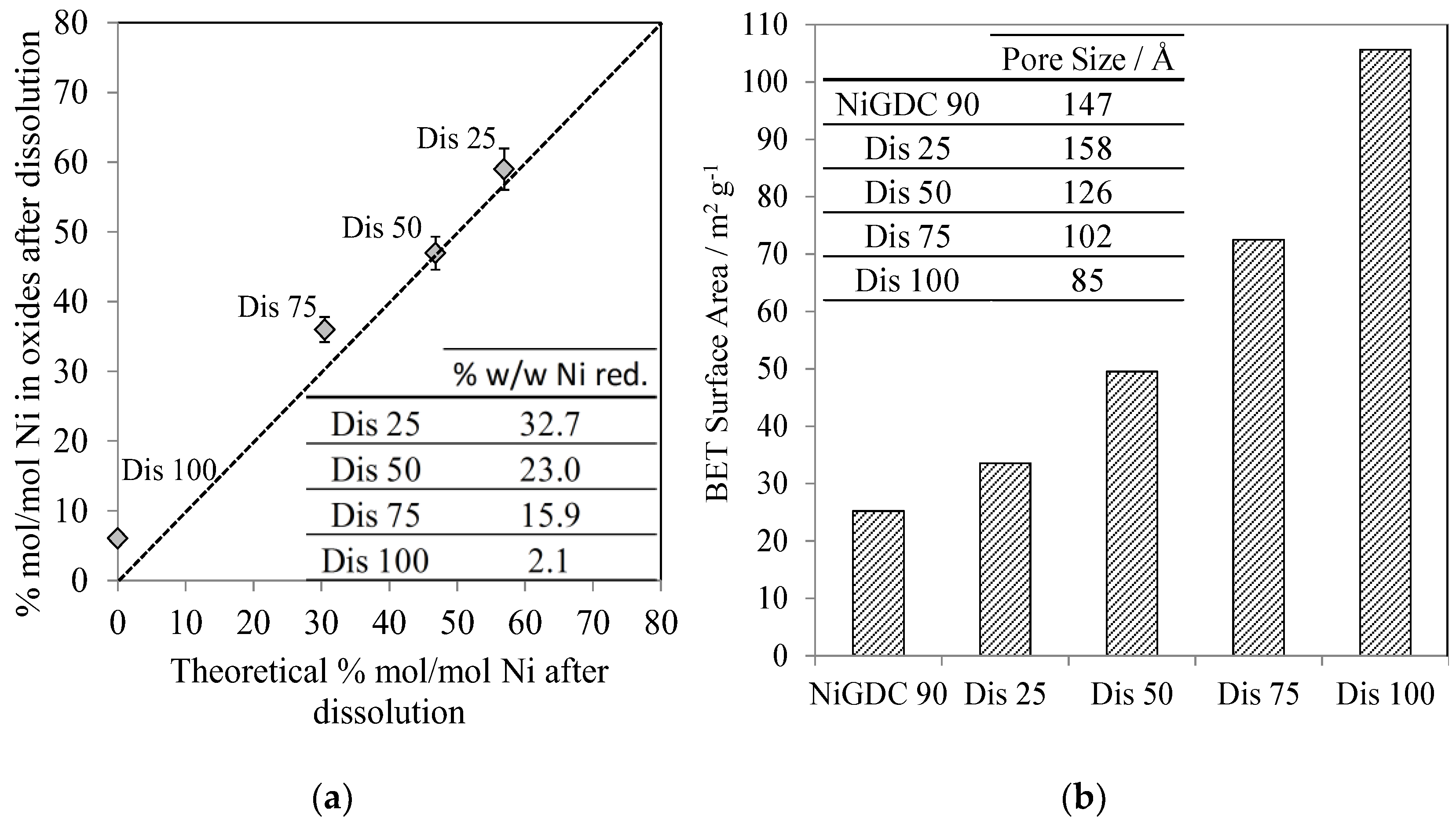
In addition, a small amount of the solid materials obtained after partial dissolution, filtering, washing, and drying (Supplementary Materials, Section 1.2) was dissolved and then analyzed via ICP-AES (Figure 3a). First of all, it could be observed that the final loading of the materials was fairly similar to the theoretical loading assuming the stoichiometric dissolution of NiO. In addition, the table inset in Figure 3a shows the Ni weight loading if Ni were reduced (as previously demonstrated in Table 1) on GDC. A wide variety of Ni loadings were achieved, varying from 2 (sample Dis 100) to 33 wt % (sample Dis 25).
The obtained solid materials were also analyzed by XRD (Supplementary Materials, Figure S4 and Table S1). As previously observed, for all these materials, a first set of diffraction peaks is characteristic of GDC fluorite structure, with lattice parameters from 5.4214 to 5.4246 Å. In addition, NiO peaks were observed. It is worth noting that the crystallite sizes of GDC and Ni (~10 nm) are not modified in a significant way after the HNO3 dissolution procedure.
The SSA of this new series of materials was analyzed by the BET method (Figure 3b). The SSA strongly increased from 25 (starting material, NiGDC 90, with a Ni loading of 37% w/w), to 105 m2 g−1 (Dis 100, with a Ni loading of 2% w/w).
These results clearly demonstrate, for the first time, that the whole synthesis procedure (WAR + partial NiO dissolution) leads to the production of NiO/GDC materials with high Ni loadings, small Ni crystallite sizes, and high SSAs without modifying the GDC structure. For instance, the materials called Dis 50 and Dis 75, with Ni loadings of 23 and 16% w/w, respectively, exhibit high SSAs of ~50 and 72 m2 g−1, respectively. These values are much higher than those previously reported for Ni/GDC catalysts with loadings around 10 wt % [6,8].
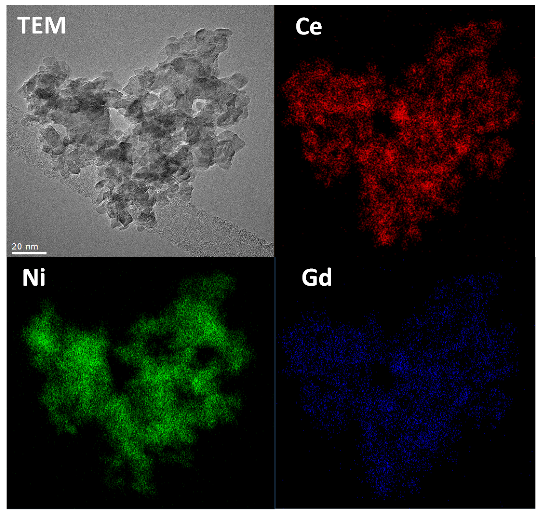
Finally, TEM measurements were carried out on the Dis 50 sample as a representative example (Figure 4). The presence of Ce, Gd, and Ni was confirmed by EDX analysis (Energy-dispersive X-ray spectroscopy). EDX mappings of the different elements have clearly shown that the catalyst is very homogeneous, containing well dispersed NiO nanoparticles in the GDC matrix. In addition, in good agreement with the XRD measurements, both GDC and NiO nanoparticles exhibit a small particle size (6–10 nm). Additional TEM images and EDX and FFT analysis are shown in Figures S5 and S6 and Table S3 (Supplementary Materials), confirming the presence, distribution, and low size of the NiO nanoparticles on the GDC support.
3. Experimental
Briefly, a polyacrylic resin in the form of micro-spherical beads (630–800 μm) was pre-treated in an NH3 solution. Then, a solution of the selected elements (Ce, Gd, and Ni) in the desired concentrations was prepared and stirred in contact with the resin for 24 h. Drying (110 °C) and calcination (750 °C) treatment in air of the metal loaded resin allows for the oxidization of the organic skeleton of the resin, leaving an intimate mixture of Gadolinia-Doped Ceria and Ni oxide [9]. Finally, a material with a selected composition was treated in an HNO3 solution, aimed at the partial/selective dissolution of NiO [10]. This enhances the open porosity and therefore the specific surface area of this material (see Supplementary Materials for detailed synthesis and characterization techniques, Sections 1.1–1.3).
4. Conclusions
Novel Ni/GDC materials with advanced nanostructural properties have been developed in this study following a new synthesis procedure which involved (a) an ionic exchange of all metal cations in a once-through procedure followed by a thermal treatment in air at 750 °C and (b) the partial NiO dissolution to enhance the SSA. Therefore, these novel materials exhibit very promising properties, in comparison with other conventional preparation methods (incipient wetness impregnation, etc.), in view of their application to the catalytic reforming of methane for hydrogen production.
Supplementary Materials
The following are available online at https://www.mdpi.com/2073-4344/7/12/368/s1, Experimental details (synthesis and characterization), preparation of Ni/GDC catalysts, additional TGA and ICP-AES analysis, and complementary TEM/STEM-EDX analysis. Figure S1: (a) Thermogravimetric analysis of the first set of loaded resin materials performed under air (20 mL min−1); (b) Exchange efficiency, calculated on the basis of the TGA and ICP-AES results, Figure S2: Thermogravimetric analysis of the sample NiGDC 90 prepared in the first series of loaded resin materials, Figure S3: (a) ICP-AES analysis of the second series catalysts after the NiO partial dissolution regarding the concentration of Ce, Gd and Ni in the HNO3 solution used to dissolve NiO; (b) Comparison of Ni concentration in the HNO3 solution after partial dissolution, and the theoretical amounts expected, considering stoichiometric dissolution of NiO with HNO3, Figure S4: XRD patterns of the second series of catalysts after the NiO partial dissolution, Figure S5: TEM image of catalyst Dis 50 (50% of Ni in starting material, NiGDC 90, was selectively dissolved), Figure S6: EDX analysis of the areas highlighted on Figure S5, Table S1: Lattice Parameters, crystallite size and strain of GDC and NiO, for the 1st and 2nd series of catalysts, based on the XRD measurements, Table S2: % mol/mol Ni and % w/w of Ni (if it was reduced) according to ICP-AES analysis, and Specific Surface Area (BET) of the catalysts after calcination of the loaded resin, Table S3: Fast Fourier Transform (FFT) analysis of selected area on Figure S5.
Acknowledgments
Financial support by Agence Nationale de la Recherche (ANR, project ANR-15-CE08-0017) and the European Commission (Enhanced Eurotalents programme, N/Ref INSTN/SFRES/ASL/2016-715) are gratefully acknowledged.
Author Contributions
A. Caravaca, S. Picart, T. Delahaye and P. Vernoux conceived and designed the experiments; A. Caravaca performed the synthesis experiments, analyzed the data and wrote the first draft of the paper (corrected by the rest of authors); B. Arab-Chapelet performed and analyzed the XRD results; M. Aouine performed and analyzed the results from E-TEM.
Conflicts of Interest
The authors declare no conflict of interest.
References
- Lahijani, P.; Zainal, Z.A.; Mohammadi, M.; Mohamed, A.R. Conversion of the greenhouse gas CO2 to the fuel gas CO via the Boudouard reaction: A review. Renew. Sustain. Energy Rev. 2015, 41, 615–632. [Google Scholar] [CrossRef]
- Khani, Y.; Shariatinia, Z.; Bahadoran, F. High catalytic activity and stability of ZnLaAlO4 supported Ni, Pt and Ru nanocatalysts applied in the dry, steam and combined dry-steam reforming of methane. Chem. Eng. J. 2016, 299, 353–366. [Google Scholar] [CrossRef]
- Ali, S.; Al-Marri, M.J.; Abdelmoneim, A.G.; Kumar, A.; Khader, M.M. Catalytic evaluation of nickel nanoparticles in methane steam reforming. Int. J. Hydrog. Energy 2016, 41, 22876–22885. [Google Scholar] [CrossRef]
- Huang, T.-J.; Lin, H.-J.; Yu, T.-C. A comparison of oxygen-vacancy effect on activity behaviors of carbon dioxide and steam reforming of methane over supported nickel catalysts. Catal. Lett. 2005, 105, 239–247. [Google Scholar] [CrossRef]
- Huang, T.-J.; Wang, C.-H. Methane decomposition and self de-coking over gadolinia-doped ceria-supported Ni catalysts. Chem. Eng. J. 2007, 132, 97–103. [Google Scholar] [CrossRef]
- Huang, T.-J.; Yu, T.-C. Effect of steam and carbon dioxide pretreatments on methane decomposition and carbon gasification over doped-ceria supported nickel catalyst. Catal. Lett. 2005, 102, 175–181. [Google Scholar] [CrossRef]
- Huang, T.-J.; Yu, T.-C.; Jhao, S.-Y. Weighting Variation of Water-Gas Shift in Steam Reforming of Methane over Supported Ni and Ni−Cu Catalysts. Ind. Eng. Chem. Res. 2006, 45, 150–156. [Google Scholar] [CrossRef]
- Huang, T.-J.; Huang, M.-C.; Huang, M.-S. Novel methane steam-reforming catalyst of Ni-Bi2O3/GDC to reduce CO for hydrogen production. Appl. Catal. A Gen. 2009, 354, 127–131. [Google Scholar] [CrossRef]
- Delahaye, T.; Caisso, M.; Picart, S. Procede de Preparation d’un Materiau Composite du Type Cermet Mettant en Uvre une Resine Echangeuse D’ions. French Patent EP3034209 A1, 22 June 2016. Available online: https://encrypted.google.com/patents/EP3034209A1?cl=fr&hl=es (accessed on 27 November 2017).
- Delahaye, T.; Caisso, M.; Picart, S. Method for Preparing an Oxide Ceramic Substrate Using an Ion Exchange Resin. French Patent EP3034483 A1, 22 June 2016. Available online: http://www.google.com/patents/EP3034483A1?cl=en (accessed on 27 November 2017).
- Walton, H.F. Ion Exchange; Helfferich, F.G., Ed.; Mcgraw-Hill: New York, NY, USA, 1962; Volume 138, p. 133. [Google Scholar]
- Caisso, M.; Lebreton, F.; Horlait, D.; Picart, S.; Martin, P.M.; Bès, R.; Renard, C.; Roussel, P.; Neuville, D.R.; Dardenne, K.; et al. Nanostructured gadolinium-doped ceria microsphere synthesis from ion exchange resin: Multi-scale in-situ studies of solid solution formation. J. Solid State Chem. 2014, 218, 155–163. [Google Scholar] [CrossRef]
- Remy, E.; Picart, S.; Grandjean, S.; Delahaye, T.; Herlet, N.; Allegri, P.; Dugne, O.; Podor, R.; Clavier, N.; Blanchart, P.; et al. Calcined resin microsphere pelletization (CRMP): A novel process for sintered metallic oxide pellets. J. Eur. Ceram. Soc. 2012, 32, 3199–3209. [Google Scholar] [CrossRef]
- Picart, S.; Parant, P.; Caisso, M.; Remy, E.; Mokhtari, H.; Jobelin, I.; Bayle, J.P.; Martin, C.L.; Blanchart, P.; Ayral, A.; et al. Porous metal oxide microspheres from ion exchange resin. Eur. Phys. J. Spec. Top. 2015, 224, 1675–1687. [Google Scholar] [CrossRef]
- Sørensen, O.T. Thermodynamic studies of the phase relationships of nonstoichiometric cerium oxides at higher temperatures. J. Solid State Chem. 1976, 18, 217–233. [Google Scholar] [CrossRef]
- Caisso, M.; Boulesteix, R.; Picart, S.; Maître, A.; Delahaye, T.; Ayral, A. Investigation of the sintering mechanisms of GDC pellets obtained by the compaction of nanostructured oxide microspheres. J. Am. Ceram. Soc. 2017, 100, 4450–4460. [Google Scholar] [CrossRef]
Figure 1.
(a) mol % Ni on the first series of catalysts after calcination, measured via ICP-AES analysis of the solid materials, and the liquid solutions before and after exchange; (b) Ce/Gd ratio of the catalysts based on the ICP-AES analysis of the catalysts after calcination.
Figure 1.
(a) mol % Ni on the first series of catalysts after calcination, measured via ICP-AES analysis of the solid materials, and the liquid solutions before and after exchange; (b) Ce/Gd ratio of the catalysts based on the ICP-AES analysis of the catalysts after calcination.
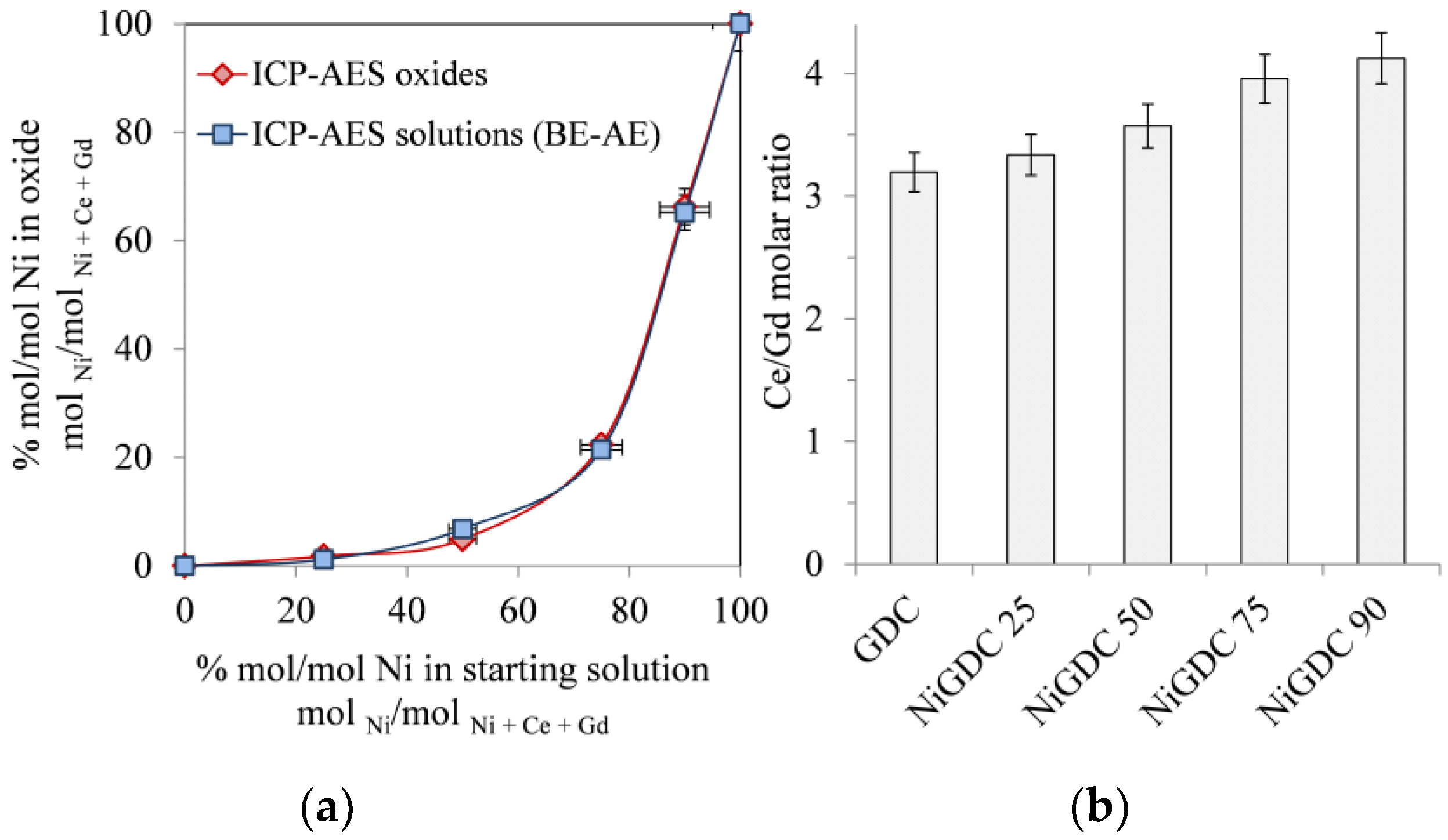
Figure 2.
XRD patterns of the first series of catalysts after calcination at 750 °C.
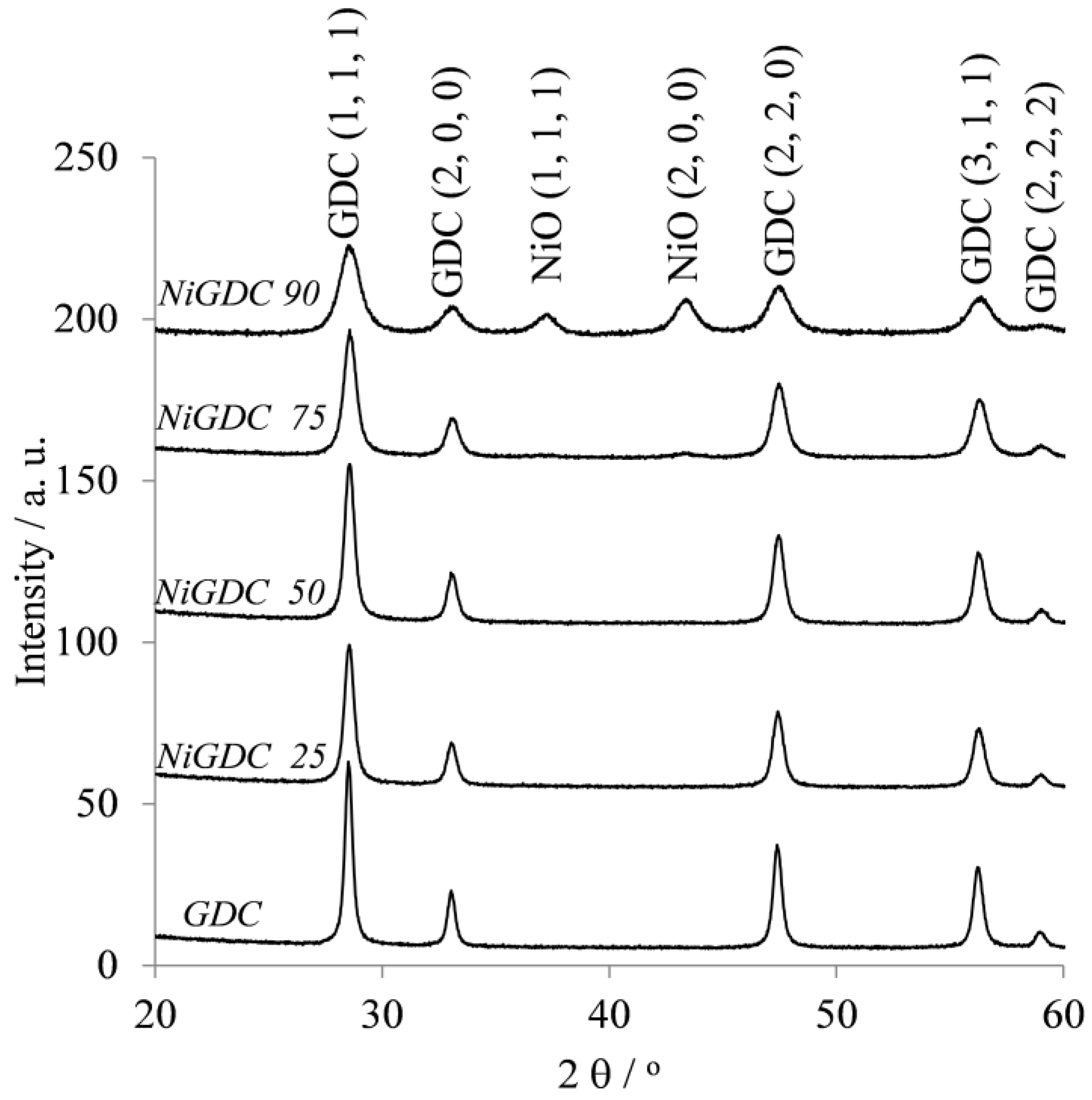
Figure 3.
(a) mol % Ni in the 2nd series of catalysts after partial NiO dissolution in the starting material (NiGDC 90) based on ICP-AES measurements of the oxide catalysts; (b) SSA and average pore size of the 2nd series of catalysts.
Figure 3.
(a) mol % Ni in the 2nd series of catalysts after partial NiO dissolution in the starting material (NiGDC 90) based on ICP-AES measurements of the oxide catalysts; (b) SSA and average pore size of the 2nd series of catalysts.

Figure 4.
TEM image of catalyst Dis 50 (50% of Ni in starting material, NiGDC 90, was selectively dissolved), and EDX mapping of Ce, Ni, and Gd.
Figure 4.
TEM image of catalyst Dis 50 (50% of Ni in starting material, NiGDC 90, was selectively dissolved), and EDX mapping of Ce, Ni, and Gd.

Table 1.
Specific Surface Area (BET), average pore size (BJH), and wt % of Ni (if it was reduced) of the first series of catalysts after calcination.
Table 1.
Specific Surface Area (BET), average pore size (BJH), and wt % of Ni (if it was reduced) of the first series of catalysts after calcination.
| Specific Surface Area/m2 g−1 | BJH Average Pore Size/Å | wt % Ni Reduced mg Ni/(mg Ni + mg GDC) | |
|---|---|---|---|
| GDC | 14 (1) | 204 | 0.0 |
| NiGDC 25 | 15 (1) | 202 | 0.6 |
| NiGDC 50 | 14 (1) | 214 | 1.7 |
| NiGDC 75 | 13 (1) | 182 | 8.9 |
| NiGDC 90 | 26 (1) | 165 | 39.8 |
© 2017 by the authors. Licensee MDPI, Basel, Switzerland. This article is an open access article distributed under the terms and conditions of the Creative Commons Attribution (CC BY) license (http://creativecommons.org/licenses/by/4.0/).
Share and Cite
MDPI and ACS Style
Caravaca, A.; Picart, S.; Aouine, M.; Arab-Chapelet, B.; Vernoux, P.; Delahaye, T. Development of Highly Nano-Dispersed NiO/GDC Catalysts from Ion Exchange Resin Templates. Catalysts 2017, 7, 368. https://doi.org/10.3390/catal7120368
AMA Style
Caravaca A, Picart S, Aouine M, Arab-Chapelet B, Vernoux P, Delahaye T. Development of Highly Nano-Dispersed NiO/GDC Catalysts from Ion Exchange Resin Templates. Catalysts. 2017; 7(12):368. https://doi.org/10.3390/catal7120368
Chicago/Turabian StyleCaravaca, Angel, Sebastien Picart, Mimoun Aouine, Benedicte Arab-Chapelet, Philippe Vernoux, and Thibaud Delahaye. 2017. "Development of Highly Nano-Dispersed NiO/GDC Catalysts from Ion Exchange Resin Templates" Catalysts 7, no. 12: 368. https://doi.org/10.3390/catal7120368
Note that from the first issue of 2016, this journal uses article numbers instead of page numbers. See further details here.