1. Introduction
Platinum (Pt) has long been used as an electrocatalyst for fuel cells but because of its high cost, and the fact that it is a source-limited material, the search for new electrocatalysts is a very important issue. Therefore, we have studied the possibility of using hydrogen storage intermetallic compounds as anode active materials for application in proton exchange membrane fuel cells (PEMFCs). The AB5-type hydrogen storage alloy (HSA), which has already been widely used as the common negative material for the Ni/MH battery, has been selected as the research’s point of departure. Beginning with the mechanically pulverized MlNi3.6Co0.85Al0.3Mn0.3 (Ml: La-rich mischmetal) alloy, a series of modifications including particle size reducing, surface chemical treatment and surface chemical coating, have been investigated in order to improve the electrochemical activity and stability of the materials in operating conditions. A porous structure electrode using the above-mentioned alloy as gas diffusion electrode (GDE) was designed and fabricated. The performance and operating life of the HSA anode was examined.
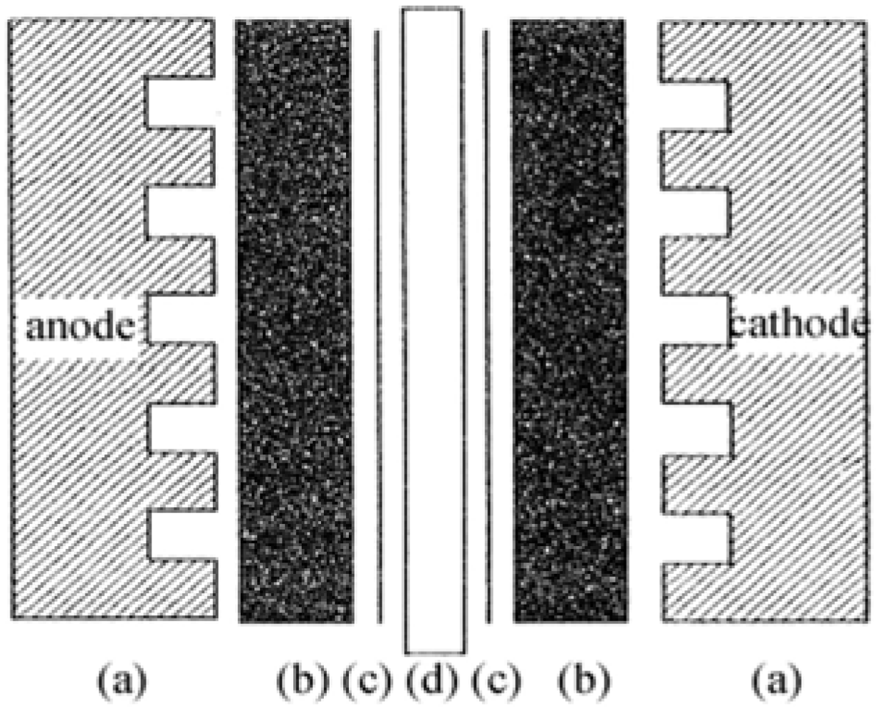
The membrane electrode assembly (MEA) is the core part of a PEMFC, as displayed in
Figure 1.
Figure 1.
Schematic structure of a membrane electrode assembly (MEA).
Figure 1.
Schematic structure of a membrane electrode assembly (MEA).
The MEA is the key component that controls the performance, energy distribution density and operating life of the PEMFC. The electrode materials and electrode fabrication techniques are essential factors in determining the cell performance.
In a GDE of a PEMFC, one strategy to improve performance is to increase three-phase boundary (TPB) sites. By introducing bulk ionic transport, hydrogen can be oxidized to H
+ over a significant portion of the electrode, thereby extending the size of the active region and improving the kinetics. To enlarge the three-dimension reaction zone, extending the active material far from the electrode/electrolyte interface, the contact area between the electronically conductive HSA and the ionically conductive polymer electrolyte must be maximized. A technique of impregnating PTFE bonded electrodes by Nafion solution is frequently used to extend the TPB sites because Nafion provides the path for proton transfer [
1,
2,
3,
4,
5].
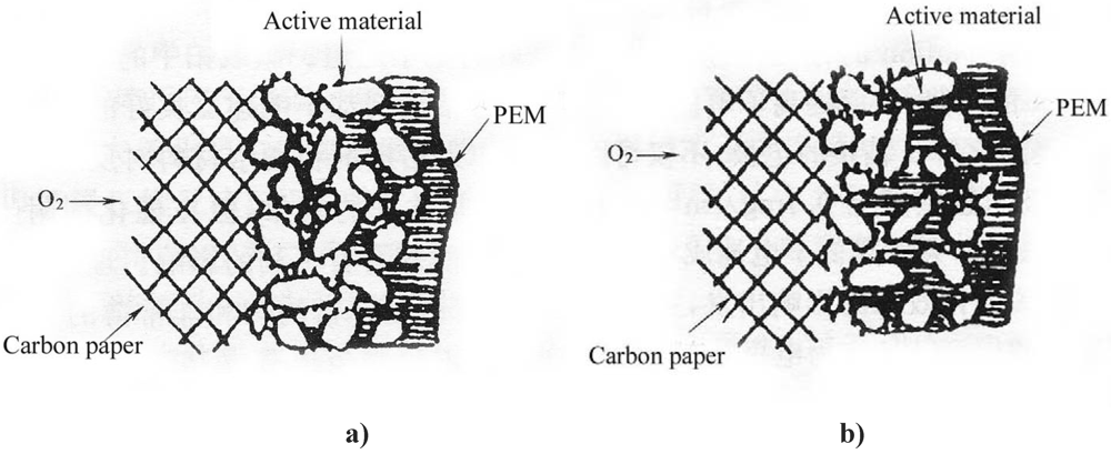
Figure 2 illustrates the schematic diagrams of the three-phase reaction zone of a GDE.
Without Nafion impregnation, the electrochemical reaction mainly proceeds in the electrolyte-wettable pores, while the sub-pores are hydrophobic due to the presence of PTFE and the active area has only a path for gas (
Figure 2a). After impregnation of a PTFE-bonded electrode with Nafion solution, this solution penetrates into the electrode micro- or mesopores, creating more TPB sites away from the front reaction zone of the proton exchange membrane (PEM). Nafion fills in the sub-pores driven by surface tension (
Figure 2b). Consequently, the sub-pores become part of the electrochemical reaction zone due to the presence of proton conductors and reaction gas, leading to more active material involved in the electrochemical reaction.
Figure 2.
Schematic diagrams of the three-phase reaction zone of a gas diffusion electrode (GDE). a) PTFE-bonded electrode without Nafion impregnation. b) Nafion impregnated electrode.
Figure 2.
Schematic diagrams of the three-phase reaction zone of a gas diffusion electrode (GDE). a) PTFE-bonded electrode without Nafion impregnation. b) Nafion impregnated electrode.
Many intermetallic compounds are capable of reversibly absorbing large amounts of hydrogen at appropriate conditions. Charging can be done using molecular hydrogen gas or hydrogen atoms from an electrolyte [
6]. As a typical example of rare earth type alloys, LaNi
5-based alloys show promising properties including high hydrogen storage capacity, fast and reversible hydrogen absorption/desorption kinetics with small hysteresis, and good life-cycle [
6]. Due to these attractive properties, LaNi
5 series HSAs are already widely used in metal-hydrogen engineering application fields.
The major problem involved in the electrochemical application of alloys, particularly for use in the Ni/MH battery, is the decrease of the metal hydride (MH) electrode capacity due to the continuous oxidation and pulverization of HSAs during the charging/discharging cycles. It was reported that an approach to reduce such degradation is by surface chemical coating [
7,
8,
9,
10,
11,
12,
13,
14,
15,
16]. The coating not only improves the cyclic stability of HSAs, but also remarkably increases the electrocatalytic activity and the rate of the charging/discharging ability.
In this work, the HSA used as anode active material of the PEMFC was the mischmetal based AB5-type material MlNi3.6Co0.85Al0.3Mn0.3. At the A side Ml was La-rich mischmetal composed of 61.3 wt.% La, 26.2 wt.% Ce, 3.1 wt.% Pr, 8.4 wt.% Nd, and total mischmetal content was 99%; as for the B side it was designed to be slightly overstoichiometric, as AB5.05. The overstoichiometric composition at the B side was intended to improve the electrocatalytic properties of the HSA. The use of the La-rich mischmetal was expected to decrease the pressure-composition isotherm (p-c-T) plateau and therefore enhance hydrogen sorption ability at lower temperatures.
2. Experimental
The MlNi3.6Co0.85Al0.3Mn0.3 based HSA was fabricated in an Al2O3 crucible using a RF induction furnace equipped with a vacuum system. The purity of the selected components Ni, Co, Al, Mg, Mn, Ca was higher than 99 wt.%. The samples were remelted 3 times to assure good homogeneity. The chemical compositions of the product were analyzed by inductively coupled plasma spectroscopy (ICP) to be consistent with the designed compositions.
The ingot alloy bulks were firstly mechanically pulverized into powders with a dimension of less than 200 mesh. The powder thus prepared was introduced into a stainless steel vial together with stainless steel balls (diameter: 10 mm). The weight ratio of the powder to the balls was 1:20. The vial was then evacuated, filled with three different ball-milling media including high purity argon, hydrogen gas and ethanol, respectively, and tightly sealed. The samples were then ball-milled by the QM-1SP Planetary Ball Mill at a rate of 225 rpm and the ball-milling time was set as required.
Part of the milled powder was submitted to surface modifications. The modification was done by immersing the powder in a 6 M KOH alkaline solution containing 0.01 M KBH4 at 80 °C. The weight ratio of alloy powder to treatment solution was 1 g to 5 mL and the treatment was performed for a period of 3 h. After the treatment, the alloy powder was rinsed with distilled water and then dried in a vacuum chamber.
A further chemical coating modification of palladium on the above surface modified HSA was conducted in order to enhance the resistance against the attack from acidic operating environment. At room temperature, a coating solution was prepared by adding PdCl2 (61 wt% of Pd in total) into 36~38% HCl solution and adding NH4Cl, NaH2PO2·H2O in sequence and using DI water and ammonia to adjust the pH of the solution. In the coating procedure, the prepared solution and HSA was mixed in the weight ratio of 1 g HSA to 0.03 g Pd in solution. The mix solution was ultrasonically dispersed at 35 °C for 15 min. The weight gain of the Pd coated alloy powder was measured to be controlled in ~3 wt%.
For preparing the MEA, Pt-dispersed carbon (Pt/C) powder with a Pt content of 39 wt.% (Product No. 44830, Alfa Aesar) was employed as electrocatalyst of the MEA. Nafion 115 membrane (Product No. 42179, Alfa Aesar) and 5 wt.% Nafion solution (Product No. 42117, Alfa Aesar) were employed as PEM and proton conducting material for the impregnation, respectively. A sheet of carbon fiber paper (TGP-H-060, 190 μm in thickness, Toray Composites America, Inc.) was soaked in a PTFE solution for hydrophobic treatment, to be used as the MEA diffusion layer. An ink prepared by mixing the active material with PTFE and Nafion solution was sprayed onto the carbon diffusion layer. All parts including the electrodes and membrane were assembled in sequence as shown in
Figure 1. The assemblies were then submitted to hot-press at 120–200 °C, using a pressure of 30–60 kg cm
–2 for 100 s, to obtain the final MEAs. The MEAs were tested in a PEMFC test stand using conventional electrochemical equipment.
The measurement of the p-c-T for the HSA sample was determined by the Sieverts method and examined on a HI-980001 type p-c-T apparatus. The alloy sample was ground to below 200 mesh in advance. The particle size, distribution and the specific surface area analysis were carried out by a Mastersizer 2000 Particle Size Analyzer (PSA) from Malvern Instruments.
Before recording the experimental data, 4 to 5 hydriding/dehydriding cycles were applied to activate the sample. The electrochemical properties of a PEMFC MEA using the HSA as anode active material were studied.
3. Results and Discussion
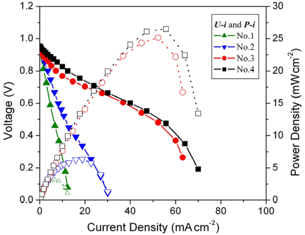
The cell voltage
vs. current density (
U-
i characteristics) plots for the MEAs with different loading amounts of mechanical pulverized HSA anode active material are shown in
Figure 3, corresponding to
Table 1.
Table 1.
Selected electrocatalysts and loading amounts for the tested MEAs.
Table 1.
Selected electrocatalysts and loading amounts for the tested MEAs.
| MEA sample No. | Pt/C cathode loading amount (mg cm–2) | HSA anode loading amount (mg cm–2) |
|---|
| No.1 | 10 | 0.08 |
| No.2 | 10 | 0.15 |
| No.3 | 10 | 0.5 |
| No.4 | 10 | 1 |
Figure 3.
Cell performance of MEAs with different hydrogen storage alloy (HSA) anode loading amount. Operating conditions: A = 1 cm2, PH2 = PO2 = 2 atm, Tcell = Tanode = Tcathode = 60 °C. Open symbols refer to the RH scale.
Figure 3.
Cell performance of MEAs with different hydrogen storage alloy (HSA) anode loading amount. Operating conditions: A = 1 cm2, PH2 = PO2 = 2 atm, Tcell = Tanode = Tcathode = 60 °C. Open symbols refer to the RH scale.
Open circuit voltages (OCVs) of all MEA samples are rather close (~0.99 V). When the loading amounts increase from 0.08 g cm–2 to 0.15 g cm–2, the performance of the corresponding cells improve, with the current densities increasing from 5.7 mA cm–2 to 11.2 mA cm–2 at a constant voltage of 0.5 V. When the loading amounts of HSA reach 0.5 g cm–2 and 1 g cm–2, the corresponding U-i characteristics of No.3 and No.4 MEAs are significantly increased comparing with those of No.1 and No.2 MEAs. At a load of 0.5 V, the current densities reach 50 mA cm–2 and 52.9 mA cm–2 for MEAs No.3 and No.4, respectively. The maximum power densities also increase from 2.8 mW cm–2 and 5.6 mW cm–2 for No.1 and No.2 MEAs to 25 mW cm–2 and 26.5 mW cm–2 for No.3 and No.4 MEAs.
The study of Pt catalysts revealed that the reduction of the particle size of Pt would greatly enhance its utilization rate. N. Giordano
et al. [
17] found that when the diameter of Pt is reduced to about 3 nm, the electrocatalytic activity can reach its maximum value. Accordingly, by reducing the size of active material using ball mill, one could expect to improve the MEA electrochemical properties by enlarging the specific surface area of the electrode material.
In this study, the alloy samples were modified using three different ball-mill media,
i.e., under 3 atm H
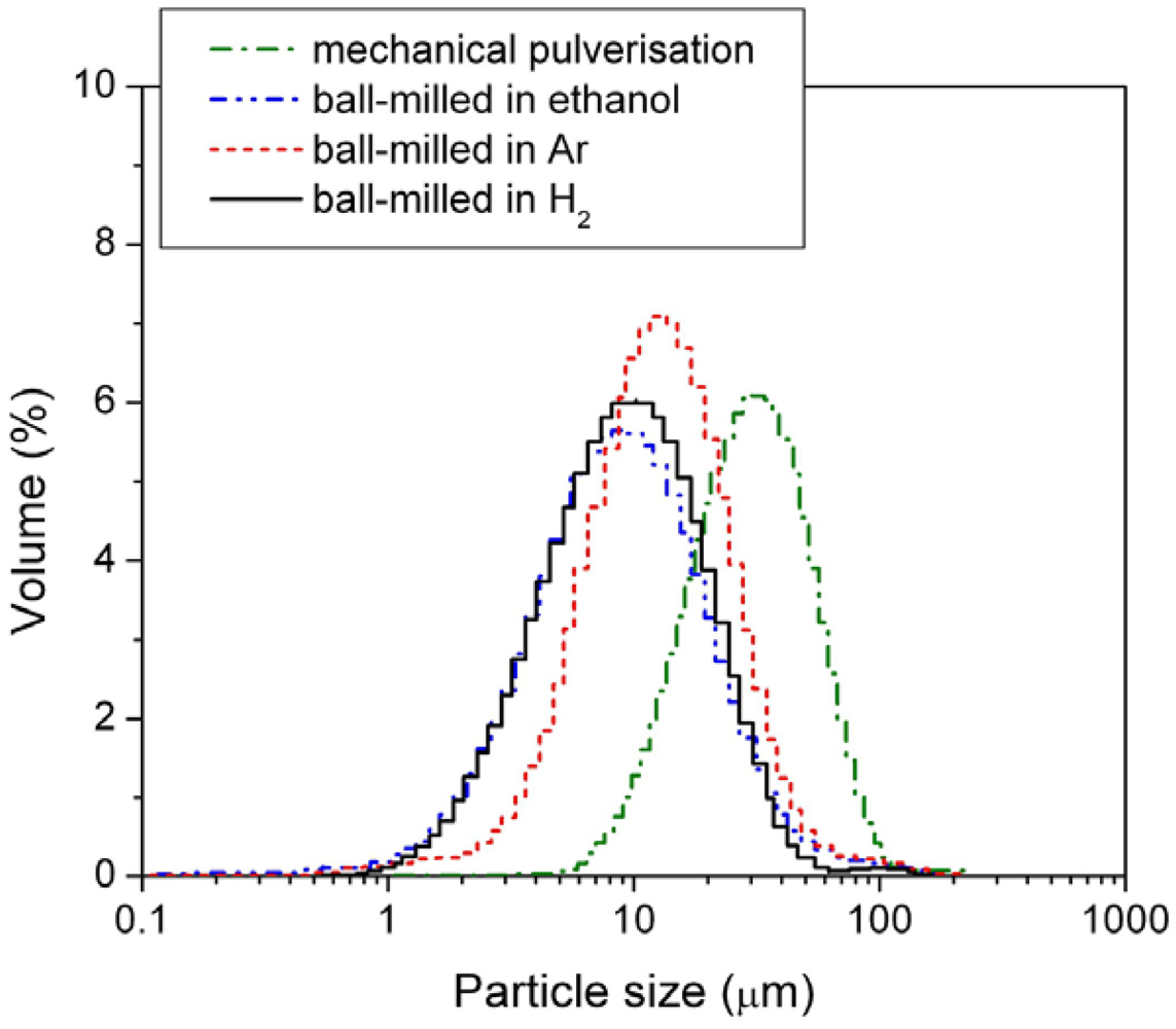
2, under 3 atm Ar, and in passivating ethanol solution. After milling, the sizes of the HSA particles were examined by the PSA. The results are shown in
Figure 4 and mean particle sizes are listed in
Table 2.
Table 2.
Mean particle size and specific surface area of the mechanically pulverised HSA and of the HSAs ball-milled in different media.
Table 2.
Mean particle size and specific surface area of the mechanically pulverised HSA and of the HSAs ball-milled in different media.
| Preparation method | Mean particle size (μm) | Specific surface area (m2 g–1) |
|---|
| Ball-milled under 3 atm H2 | 11.969 | 1.2069 |
| Ball-milled under 3 atm Ar | 12.272 | 1.1702 |
| Ball-milled in ethanol | 16.561 | 0.8096 |
| Mechanical pulverisation | 43.410 | 0.3272 |
Figure 4.
Particle size distribution of the mechanically pulverized HSA and of the HSAs ball-milled in different media.
Figure 4.
Particle size distribution of the mechanically pulverized HSA and of the HSAs ball-milled in different media.
Among the three different modification media, the HSA sample ball-milled in 3 atm H2 had the smallest mean particle size of 11.969 μm and showed the best concentrated distribution of particle size of HSA. During the ball milling in 3 atm H2, the HSA likely reacted with H2 to form the metal hydride. The material in hydride phase is much more brittle compared with the corresponding dehydrided phase, resulting in easier pulverization and the smaller in final ball mill product size.
Chemical surface treatment could improve electrochemical properties of the HSAs. One explanation is that such treatments, particularly in the current study the treatment of HSA in a hot alkaline solution containing KBH
4, can break down and reduce the oxide layer on the top surface and create Ni-rich layer/sites with high electrocatalytic activity. The involved reduction process of the metal oxide MOx can be described by the following chemical reaction equations [
18]:
![Crystals 02 00022 i001]()
Through this series of chemical reactions, the strong reductant KBH
4 can, therefore, partially reduce, or even eliminate, the nickel oxide in the surface and subsurface layers. Moreover, when the chemical reduction occurs at the oxide layer, during the process of treatment, the preferential dissolution of surface elements (such as Mn, Al, and their oxides) as a function of the corrosion induced by the hot alkaline solution, also leads to elemental Ni enrichment in the surface of the HSAs. The above two factors enhance the formation of Ni-rich layers, thus increasing the adsorbability of hydrogen and the electrocatalytic activity of the alloy surface, hence giving better electrocatalytic characteristics to the anode alloys. Further studies on the beneficial effects of borohydride solutions on the pre-treatment of HSAs for anode electrodes have also been recently reported by our group [
19,
20,
21].
Based on the studies of loading amount and ball mill products in different applied environments and associated with the discussion on surface modifications, an optimized HSA anode active material was prepared using a set of modifications including ball milling in H2 as milling media, surface modification in hot alkaline solution containing KBH4 and chemical coating with Pd. Actually, the performance of Pd is expected to follow that of Pt, since it is well known that electrocatalytic activity of the corresponding noble metals nanoparticles reach a maximum value at an average size of about 3 nm. Pd is preferred in the metal hydride case, due to their excellent absorption hydrogen properties.
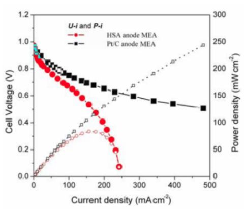
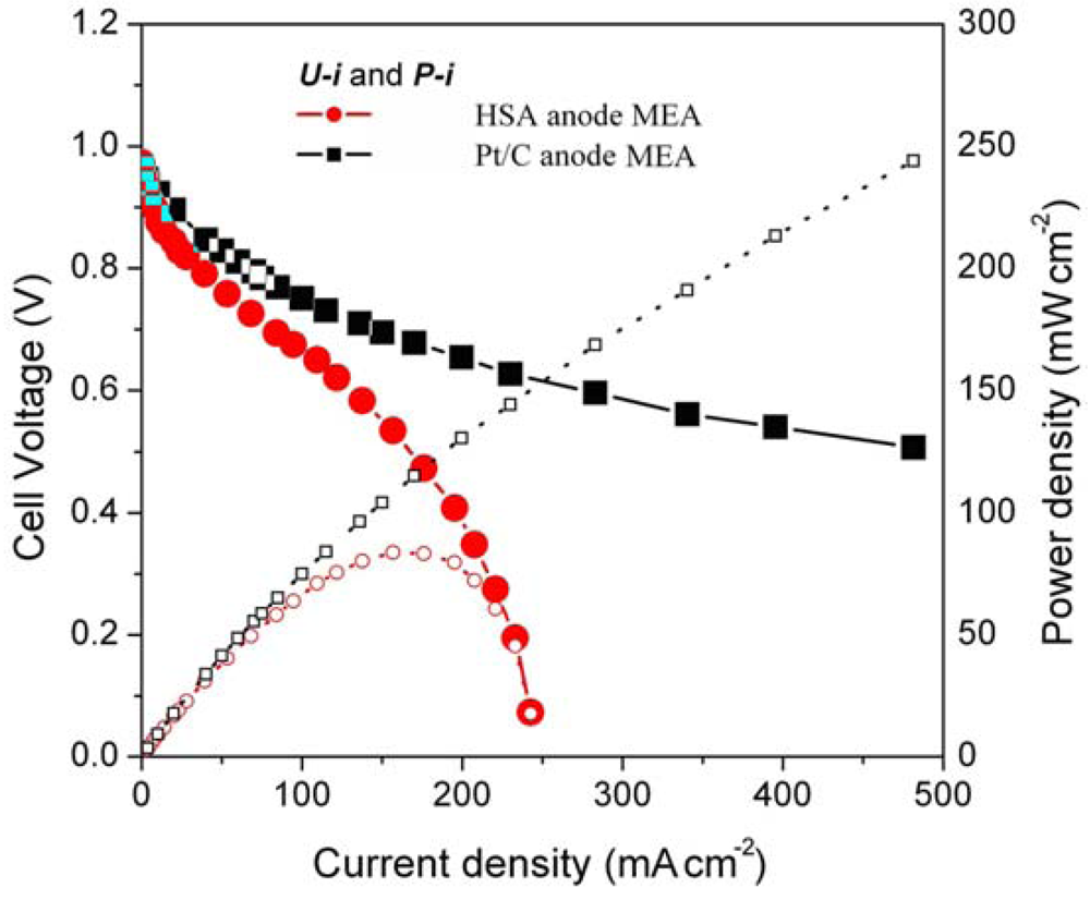
Figure 5 illustrates the
U-i and
P-i characteristics of the optimized HSA anode MEA and of the Pt/C anode MEA. It can be observed that the cell performance of the HSA anode MEA is remarkably improved (
Figure 3). The discharge current densities of the HSA anode MEA reached 168 mA cm
–2 and 232.4 mA cm
–2 at cell voltages of 0.5 V and 0.2 V, respectively, with maximum power densities of up to 84 mW cm
–2.
Figure 5.
U-i and P-i characteristics for the HSA anode MEA and for the Pt/C anode MEA. Operating conditions: A =1 cm2, PH2 = PO2 = 2 atm, Tcell = Tanode = Tcathode = 60 °C. Open symbols refer to the RH scale.
Figure 5.
U-i and P-i characteristics for the HSA anode MEA and for the Pt/C anode MEA. Operating conditions: A =1 cm2, PH2 = PO2 = 2 atm, Tcell = Tanode = Tcathode = 60 °C. Open symbols refer to the RH scale.
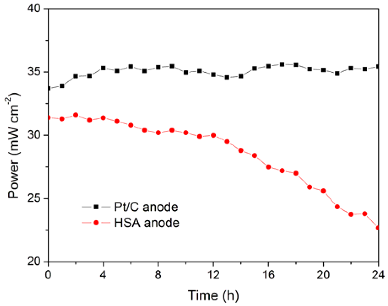
The working stabilities of the optimized HSA anode MEA and the Pt/C anode MEA at a constant current load of 40 mA/cm
2 were studied and compared. As shown in
Figure 6, the power of the HSA anode MEA was at 22.68 mW/cm
2 and 72.4 % of its initial power density after 24 h. No sign of degradation in Pt/C anode MEA implies that the use of HSA active material results in the performance degradation of the HSA anode MEA.
Figure 6.
Working stabilities of the HSA anode MEA in comparison with Pt/C MEA at a constant current load of 40 mA/cm2 (operating conditions: electrode area 1 cm2, pressure PH2 = PO2 = 2 atm; working temperature Tcell = 25 °C, wetting temperature Tanode = Tcathode = 40 °C).
Figure 6.
Working stabilities of the HSA anode MEA in comparison with Pt/C MEA at a constant current load of 40 mA/cm2 (operating conditions: electrode area 1 cm2, pressure PH2 = PO2 = 2 atm; working temperature Tcell = 25 °C, wetting temperature Tanode = Tcathode = 40 °C).
The hydrogen content of a sample of MlNi3.6Co0.85Al0.3Mn0.3, with hydrogen previously absorbed, was monitored by molecular beam-thermal desorption spectrometry (MB-TDS). The hydrogen pre-charging was performed galvanostatically using pure Pd as the anode of an electrolytic cell containing an aqueous 1 M KOH electrolyte, and imposing an electric current of 133 mA.
The dry HSA electrode was weighted with a Kern ABS analytical balance before and after the electrochemical hydrogen charging. In average, the weight difference was ~0.7 mg. The MB-TDS study of the HSA sample was performed at a heating rate of 1 °C min
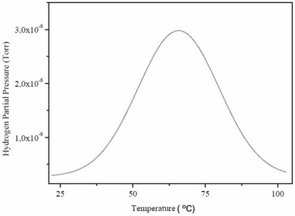
–1. The resulting desorption spectrum is shown in
Figure 7.
Figure 7.
Molecular beam-thermal desorption spectrometry (MB-TDS) spectrum of an electrochemically charged HSA sample submitted to a heating rate of 1 °C min–1.
Figure 7.
Molecular beam-thermal desorption spectrometry (MB-TDS) spectrum of an electrochemically charged HSA sample submitted to a heating rate of 1 °C min–1.
The total amount of hydrogen contained in the HSA sample was computed by considering the integral of the Gaussian MB-TDS spectrum displayed in
Figure 7, followed by subtraction of the hydrogen background pressure taken in similar experimental conditions (which was 1.0 × 10
–7 Torr).
Actually, the number of hydrogen molecules which were desorbed during the MB-TDS measurements are easily estimated from the area under the desorption curve after discounting the above-mentioned hydrogen background pressure. Such a result is 0.1 Pa s. This value is consistent with the hydrogen content in the sample previously weighted (0.7 mg) if the pumping speed is of the order of 3 × 10⁻² dm3 s–1. In fact, 0.7 mg of hydrogen corresponds to about 2 × 10²⁰ hydrogen molecules, and thus for an average temperature of 100 °C, one gets a pumping speed of about 3 × 10⁻² dm3 s–1.
However, the experimental pumping speed of the vacuum system is 10 times larger. Such discrepancy can be attributed to the geometrical fraction of the hydrogen beam effectively “seen” by the quadrupole detector and to the ionization efficiency of this detector as well [
22].
The family of hydrogen storage intermetallic compounds embraces not only rare earth based alloys. Several other types of HSAs such as Ti-based (AB and AB
2), Mg-based (AB
2, AB
3, etc.), and Zr-based (AB
2, AB, and A
2B) alloys also offer fairly good hydrogen sorption kinetics. Among these alloys, Zr-based alloys present thermodynamic features that match with the PEMFCs working temperatures, and may have better electrochemical stabilities in acidic media than rare earth based alloys. On the other hand, the Ti-based alloy pioneered by Viden
et al. in the 1970s [
23] showed promising electrochemical properties. Given the newly technical advances on the PEMFC, Ti-based alloys would deserve further reinvestigation, as well as other functional materials [
24,
25,
26].


