Article

Physiochemical Characterization of Iodine (V) Oxide Part II: Morphology and Crystal Structure of Particulate Films

by
Brian K. Little
1,*,
Samuel B. Emery
2 and
C. Michael Lindsay
3
1
University of Dayton Research Institute, U.S. Air Force Research Laboratory, Eglin AFB, FL 32542, USA
2
Naval Surface Warfare Center Indian Head Explosive Ordinance Technology Division, Indian Head, MD 20640, USA
3
Air Force Research Laboratory, Energetic Materials Branch, Eglin AFB, FL 32542, USA
*
Author to whom correspondence should be addressed.
Crystals 2015, 5(4), 534-550; https://doi.org/10.3390/cryst5040534
Submission received: 16 September 2015 / Revised: 23 October 2015 / Accepted: 26 October 2015 / Published: 2 November 2015
(This article belongs to the Special Issue Energetic Materials)

Abstract

:
In this study, the production of particulate films of iodine (V) oxides is investigated. The influence that sonication and solvation of suspended particles in various alcohol/ketone/ester solvents have on the physical structure of spin or drop cast films is examined in detail with electron microscopy, powder x-ray diffraction, and UV-visible absorption spectroscopy. Results indicate that sonicating iodine oxides in alcohol mixtures containing trace amounts of water decreases deposited particle sizes and produces a more uniform film morphology. UV-visible spectra of the pre-cast suspensions reveal that for some solvents, the iodine oxide oxidizes the solvent, producing I2 and lowering the pH of the suspension. Characterizing the crystals within the cast films reveal their composition to be primarily HI3O8, their orientations to exhibit a preferential orientation, and their growth to be primarily along the ac-plane of the crystal, enhanced at higher spin rates. Spin-coating at lower spin rates produces laminate-like particulate films versus higher density, one-piece films of stacked particles produced by drop casting. The particle morphology in these films consists of a combination of rods, plates, cubes, and rhombohedra structure.

Graphical Abstract

1. Introduction

Iodine (V) oxides (I2O5, HI3O8, and HIO3) promise to be effective oxidizers in energetic materials for various applications [1,2,3]. This potential is largely due to their ability to increase the energy density and pressure impulse in multi-component energetic composites, as well as their ability to produce gaseous iodine (I2) and corrosive hydrogen iodide (HI) during decomposition, which exhibit biocidal behavior towards biological agents such as anthrax [4,5,6,7]. Their use is complicated by the facts that the amount of gas generated, the amount of energy released, and ratio of I2 to HI generated are strongly affected by the degree of hydration of the iodine oxide. The anhydrous form, I2O5, is very hygroscopic, and thus readily forms HI3O8 in low humidity environments. The hydration rate for this process strongly depends on the available surface area of the particles (i.e., the particle size) as well as the relative humidity [8]. HI3O8 can further hydrate to HIO3 at a relative humidity > ~60%, but proceeds more slowly via a different mechanism than hydration of I2O5. Commonly HIO3 is also prepared by solvating I2O5 or HI3O8 in water followed by evaporation leaving behind crystalline HIO3 [9].
While this simple picture adequately describes bulk hydration, the processes are more complex for smaller size particles, particularly for cases where the particles have high-aspect ratios. For instance, deliquescence—the process of dissolving a solid compound by absorbing moisture from the air—plays an important role under these conditions and can drive the instability in the composition of iodine (V) oxides as well as in the morphology of resulting crystals [9]. Kumar et al. reported that the relative humidity threshold for deliquescence to occur in I2O5 and HIO3 is different in each compound and is strongly dependent on particle size as well [10]. Our group has also observed that the suspension and subsequent deposition of iodine (V) oxide-solvent mixtures exhibits a change from a precipitation-based process to a deliquescence-based process depending on the relative humidity [11]. The results of each of these studies collectively emphasize that the fabrication of fine particulate iodine oxide containing materials is an inherently complex process that depends on the balance of the competing and coupled processes of evaporation, deliquescence, precipitation, and crystal growth. Given the interest in producing fast reacting fuel-oxidizer composites for energetic material applications, which require the processing of small particles, there is a clear need to understand this competition better.
In this study, we examine the composition, morphology, particle size, and crystal structure of iodine (V) oxide processed into films, and report on processing and deposition parameters that influence the physical and chemical makeup of the resulting material. Specifically, we examine the chemical interactions of various solvents used to make iodine oxides suspensions, the change in particles upon sonication, and how these affect the particle size distribution and crystal orientation when spin or drop casted into a film. In addition, structural properties such as particle size, % theoretical maximum density (TMD), and thickness (all of which have been shown to influence the reactivity of energetic materials) were evaluated for the oxidizer particles assembled in the form of a film.

2. Background

Energetic films composed of multi-component fuel-oxidizer mixtures can be produced in a variety of ways, including a wide range of liquid and vapor based methods [12]. Aside from multi-layer physical or chemical vapor deposition [13,14,15,16,17], these methods generally involve some sort of a carrier fluid to combine, intermix, and transport the reagent materials to the deposition substrate. Wide ranging methods are available to control the morphology and fuel-oxidizer intimacy of the particles in the films such as self-assembly [18], aerogel, sol-gel based, or aerosol spray pyrolysis [19,20], and core-shell encapsulation [21,22]. Etching can be used to prepare nanostructured substrates (fuel) into which an oxidizer can be deposited [23]. Suspension of particulates coupled with ink-jet writing has also been used to fabricate energetic films [24,25,26]. In general, these and other sophisticated methods produce an intermixed material with a range of domain sizes and morphology, each coming with a range of advantageous and detrimental properties for a given application.
While perhaps not as sophisticated as those other methods, the direct deposition of intermixed suspensions [27,28] is one of the most common and well-established methods for generating particulate films. In such techniques, a substrate is coated with a layer of liquid containing suspended or solvated particles, and the carrier fluid is evaporated leaving behind a solid residue. Both dip and spin coating are well-established industrial techniques for doing this, generating uniform films with thicknesses varying from nanometers to microns [29]. The difference between these two processes is that in spin coating the substrate is rotated quickly as the liquid with suspended/solvated particles is placed onto the substrate. This rotation induces centrifugal forces onto the deposited fluid that results in the radial spreading of the fluid mixture across the substrate and strongly affects the drying rate.
In contrast to the one-step drop casting process, spin casting exhibits two stages that govern the final film thickness and particle arrangement of the film [30]. In the initial “fluid dynamic” stage, particle placement is influenced by multi-phase flow within the fluid bed being directed radially across the substrate. In the second, “drying” stage, particle placement and growth is governed by the evaporation of the fluid from the particle bed, the rate of which influences the final morphology and geometry of the particles. The switchover between the two stages depends on a balance of the viscous flow rate and the evaporation rate of the liquid media, and the equilibrium between the two and the suspended particle size distribution determines the final thickness of the film. Typically, volatile liquids such as ethanol, methanol, and acetone are utilized as they allow for a rapid “freezing” of the particle arrangement following the dynamic flow stage. However, more viscous, less volatile liquids like glycerol, octanedithiol, and dichlorobenzene can instead be used to minimize rapid evaporation and enhance the dynamic stage of the spin coat process. This control results in an inexpensive, fast, and reliable methodology, applied at the industrial level for film fabrication of dielectric, optical and microelectronic materials [28]. Remarkably, however, only a limited number of articles have been published that utilize spin coating to produce binary energetic material films [31,32,33]. While our interest is to produce and investigate such binary fuel-oxidizer energetic materials, this particular paper focuses solely on the effects of drop and spin casting of the oxidizer, given that the oxidizer seems to be most sensitively affected by the conditions of the casting process.
Critical to the ultimate reactivity of the energetic films is the resulting size [34] and morphology [35,36,37] of the constituents that make up the film, often which are significantly affected by the intermixing and deposition processes. Such environments vary broadly as well, ranging from a gentle mixing, stirring, or coalescence processes [38], to more intense milling [39], swaging, [40] or sonication processes [12,41]. Of all of these, sonication is one of the most commonly used, versatile, and significant in that it physically pulverizes solid constituents, typically in a liquid–solid slurry, into smaller fragments of a more uniform size and simultaneously increases the degree of intermixing when multiple components are present. Under some conditions ultrasound can also induce chemical change in a system and more importantly to this work, enhance crystallization in [42,43]. Under such conditions acoustic waves drive bubble formation, growth, and collapse through cavitation, which creates localized temperatures as high as 5000 °C and pressures as high as 500 atmospheres that in turn can induce chemistry [44]. Nucleation has been shown to be enhanced under such conditions that can facilitate crystallization [43]; thus, sonication can be a powerful tool to induce crystallization in liquid–solid slurries with precipitates possessing a narrow particle size distribution under the right conditions.

3. Results and Discussion

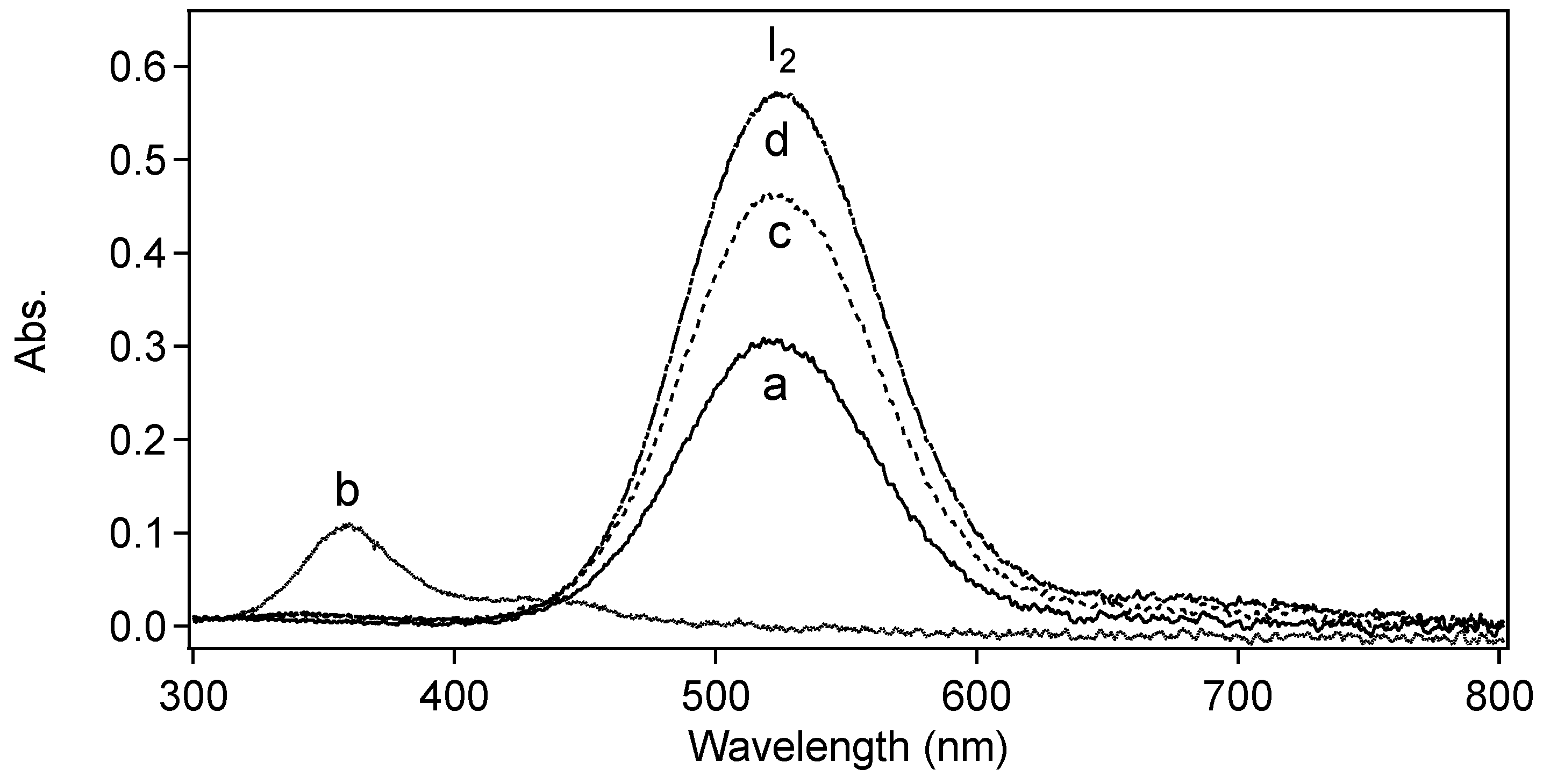
3.1. Suspensions of Iodine Oxides in Alcohols

To examine the interaction between the solvent and solute, suspensions of iodine (V) oxide were prepared by sonicating oxidizer particles in various ethanol-solvent containing mixtures under constant stirring while immersed in a temperature bath at 30 °C for a period of several weeks. The different suspensions included ethanol (200 proof), denatured ethanol, or 1:1 mixtures of one of pure ethanol liquids with methanol, 2-propanol, acetone, 2-butanone, or ethyl acetate (methanol, 2-propanol, acetone, 2-butanone, and ethyl acetate were chosen as they are the main impurities in denatured alcohol). Ethanol-based suspensions were chosen in this study given their common use to disperse aluminum and oxidizer particles for energetic mixtures along with the fact that HIO3 and I2O5 are insoluble in ethanol [45]. All samples initially consisted of a clear liquid with white precipitate, but within 24 h the liquid phase turned to yellow and then dark brown in color (see supplementary Figure S1) with additional sonication. The UV-visible spectra of the resulting liquids were very complex, indicating a variety of products of the apparent oxidation of the solvent. Figure 1 shows the UV-visible absorption spectra of approximately one drop of the liquid phase, diluted and dispersed in hexane. Most of the samples exhibit a strong absorption band at λmax = 520 nm, a well-known feature of I2 dissolved in nonpolar solvents such as hexane, n-heptane, etc. [46]. This observation is a clear indicator of the oxidation of the alcohol by the iodine oxide via reaction Scheme 1:
Scheme 1. Oxidation of Alcohol.
Crystals 05 00534 g008
In contrast, the ethanol:2-butanone solution (and confirmed with ethanol:acetone, not shown) exhibit two, weaker absorptions at λmax = 360 nm and 440 nm and the lack of the 520 nm feature. These observations strongly suggests the iodation of the ketone after oxidation of the ethanol, thereby forming the iodoketone and aqueous iodide, according to reaction Scheme 2 [47,48]:
Scheme 2. Iodination of Ketone.
Crystals 05 00534 g009
Figure 1. UV-visible absorption spectra of sonicated suspensions of HI3O8 powder in various solvents: (a) ethanol; (b) ethanol:2-butanone; (c) ethanol:ethyl acetate; and (d) denatured ethanol. All aliquots were diluted with hexane.
Crystals 05 00534 g001
It is important to note that in these experiments we chose a sample of “I2O5” from a particular lot of material supplied by Acrōs Organics. Reported elsewhere [8], we characterized the material as having few impurities, but note that it is completely in the first hydration state, HI3O8, and not the anhydrous form as advertised. This powder does show a slight pink tint on the outer surface when exposed to air, although the particle core remains white. This change in color has been observed before as an impurity, attributed to the processing method [45,49,50]. The surface discoloration is likely due to residual I2 impurity as solutions with hexane show evidence of slight purple color upon heating.
“I2O5” powder obtained from other vendors ranged in color from white to pink to yellow. Somewhat perplexing is the fact that some lots of material were only partially soluble in water, whereas others were fully soluble. Powder X-ray diffraction showed that the materials ranged in the degree of hydration, a property not correlated with the color. This is further evidence that users of iodine (V) oxides should be careful to fully characterize their material prior to use as there appears to be a wide variability of material coming from suppliers.
Another interesting observation of the post-sonicated suspensions was a lowering of the pH values. Pre-sonicated solutions reflected near neutral pH (7.0–7.4) values prior to inclusion of iodine oxide particles. High acidity concentrations could be attributed to various mechanisms such as solvation of impurities I2, oxidation of ethanol by HI3O8, and/or dissociation of HI3O8/HIO3 (pKa(HIO3) = 0.8) to name a few. Nonetheless, the presence of iodine and possibly hydrogen iodide could be significant for processing purposes with a metallized fuel particle. Iodine and more notably HI can interact with metallized particles unwantedly which could change properties of the mixture such as ignition by impact, friction and electrostatic discharge; in addition, decomposition of the oxidizer during mixing will affect the final stoichiometry of the reclaimed product powder or film.
Expectedly, the oxidization rate of the ethanol solvents by the iodine oxide increased at higher suspension temperatures, and given the heat evolved during sonication, breakdown of the solvent can occur quickly. Conversely, sinking the heat generated by the sonication by placing the suspension vessel into a cold bath significantly reduces the rate of oxidation to the point where material can be processed without noticeable discoloration of the liquid over a 12 h period. The degree of solvent oxidation when cooled below 30 °C for a period of hours was found to be sufficiently small to be suitable for processing the iodine oxide materials, and thus, was adopted for the remainder of the work presented in this manuscript.

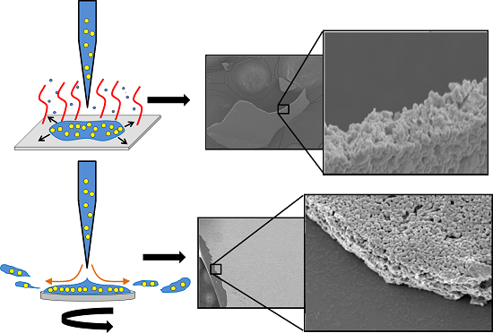
3.2. Effect of Sonication on Particle Morphology

The effect that sonication has on the morphology and composition of the iodine oxide particles was examined by comparing as-received material to material suspended in denatured ethanol, sonicated, drop-cast onto a substrate, and allowed to evaporate under dry nitrogen (~2% relative humidity). Figure 2 shows the resulting X-ray diffractograms of the two materials and the inset shows their change in morphology as observed in a scanning electron microscope (SEM). The resulting diffraction patterns are nearly identical to one another and agree with known pattern for HI3O8 (PDF # 04-011-9546) [51]. Neither iodic acid, HIO3, nor iodine pentaoxide, I2O5, were observed under these conditions, the former being somewhat surprising given that the trace amounts of water present might be expected to hydrate some of the HI3O8 into HIO3 [8].
Figure 2. Powder X-ray diffractograms of (a) as-received powder pulverized with a mortar and pestle and (b) drop cast film from a sonicated suspension of HI3O8 in denatured ethanol, deposited at ~2% relative humidity. Inset: Electron microscope images of (a) and (b).
Crystals 05 00534 g002
In contrast to the nearly identical diffraction patterns, the SEM images show a significant change in the size and the morphology of the particles upon processing the material. The as-received material exhibits a broad distribution of particle sizes and morphologies, as well as an abundance of rods with an aspect ratio of ~20:1. The sonicated and cast particles are more uniform in size and more spherical with an average diameter ~0.5 μm. It is also important to note that unlike the as-received material, which takes on a pinkish coating when exposed to air, the processed and drop-cast material exhibits no change in color when allowed to sit in the open for days, suggesting that the sonication process has washed away much of the impurity I2 from the particles that had led to the discoloration.

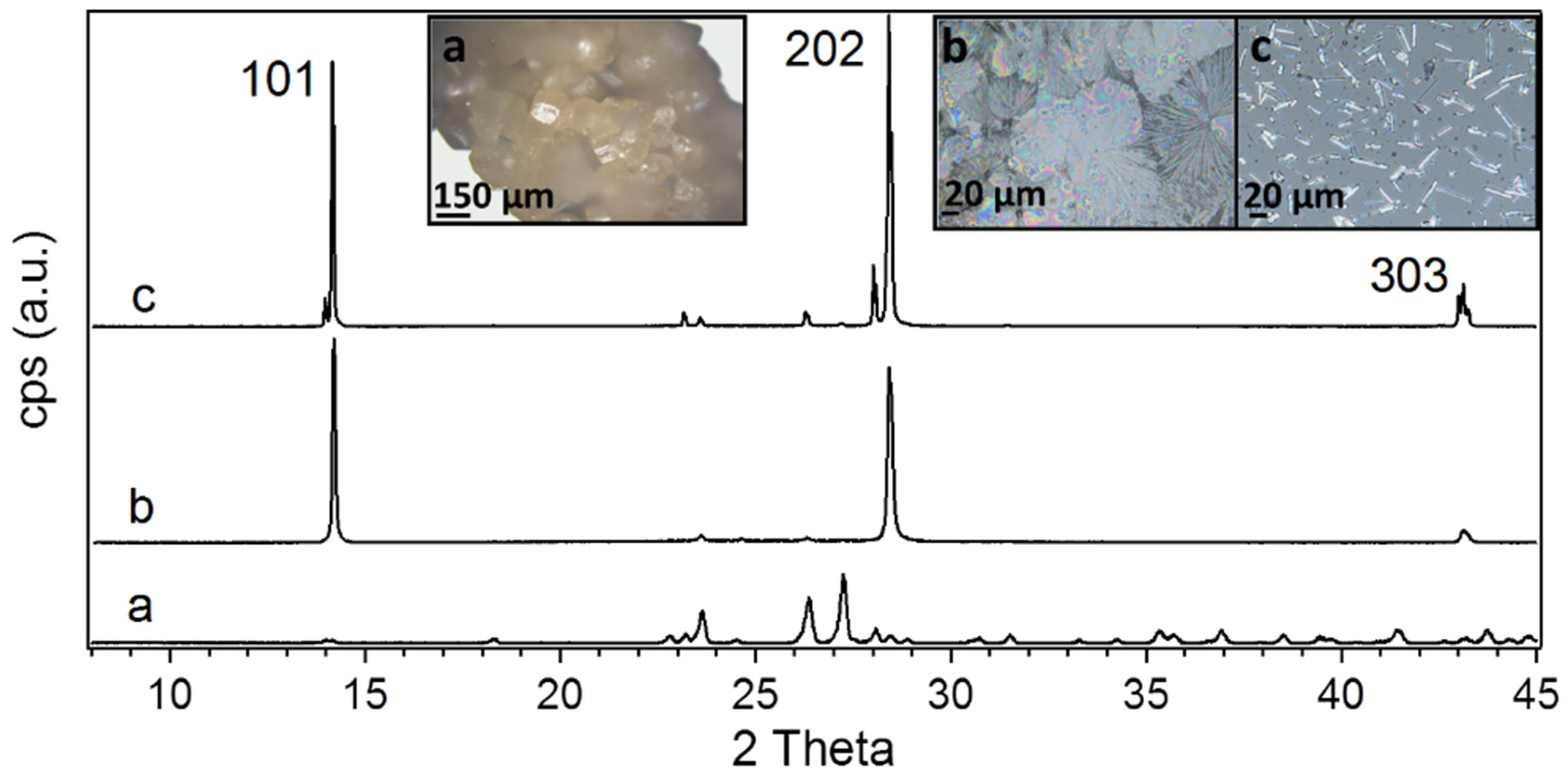
3.3. Effect of Humidity of Crystal Growth

To examine the role that humidity plays in the deposition and crystal growth process, small quantities of HI3O8 were deposited onto a borosilicate glass substrates (both drop cast or spin coat) after being sonicated in ethanol/iodine oxide suspension. In general, particles deposited at a relative humidity above >60% showed signs of deliquescence (particles submerged into liquid droplets within minutes) during the deposition process from their alcohol based suspensions, whereas films deposited at low relative humidity values (~2%) produced the highest density of particles without any visual signs of deliquescence and reflected a more uniform particle shape and size distribution (see Figure S3). Additionally, particles deposited and stored for periods of a few weeks at a relative humidity ~40% exhibited clear signs of crystal growth, producing rod, rhombohedral, plate, and needle-like structures.
Figure 3 shows the X-ray diffractograms and optical images of two examples of such grown structures (b and c) compared to the as-received material (a). Additional images of other structures are shown in supplementary Figure S2. Remarkably, the X-ray diffractograms show that the structures are composed exclusively of HI3O8 with no evidence of hydration into HIO3 in spite of the influence of humidity. This is not inconsistent with previous observations that relative humilities >65% are required to hydrate HI3O8 [8], though it is surprising the water can effect recrystallization without hydrating the material. While the 2θ diffraction angles are the same in each sample, the relative intensities of the various features in the diffractogram are very different, indicating a strong alignment in the crystal axis along which the particles grow with respect to the surface plane. Both the needle-like and the rod-like structures shown in Figure 3b,c, respectively, show strong enhancement of the diffractions corresponding to Miller indices <101>, <202> and <303>, an indication of growth along ac-crystal plane.
Figure 3. Powder X-ray diffractograms of thin-layered films cast from ethanol-based suspensions of HI3O8: (a) as-received; (b) needle-like; and (c) rod-like shaped crystals. Films (b) and (c) were produced by storing deposited films at ~40% relative humidity for a few weeks. Inset: Optical microscopy images of (a), (b), and (c).
Crystals 05 00534 g003

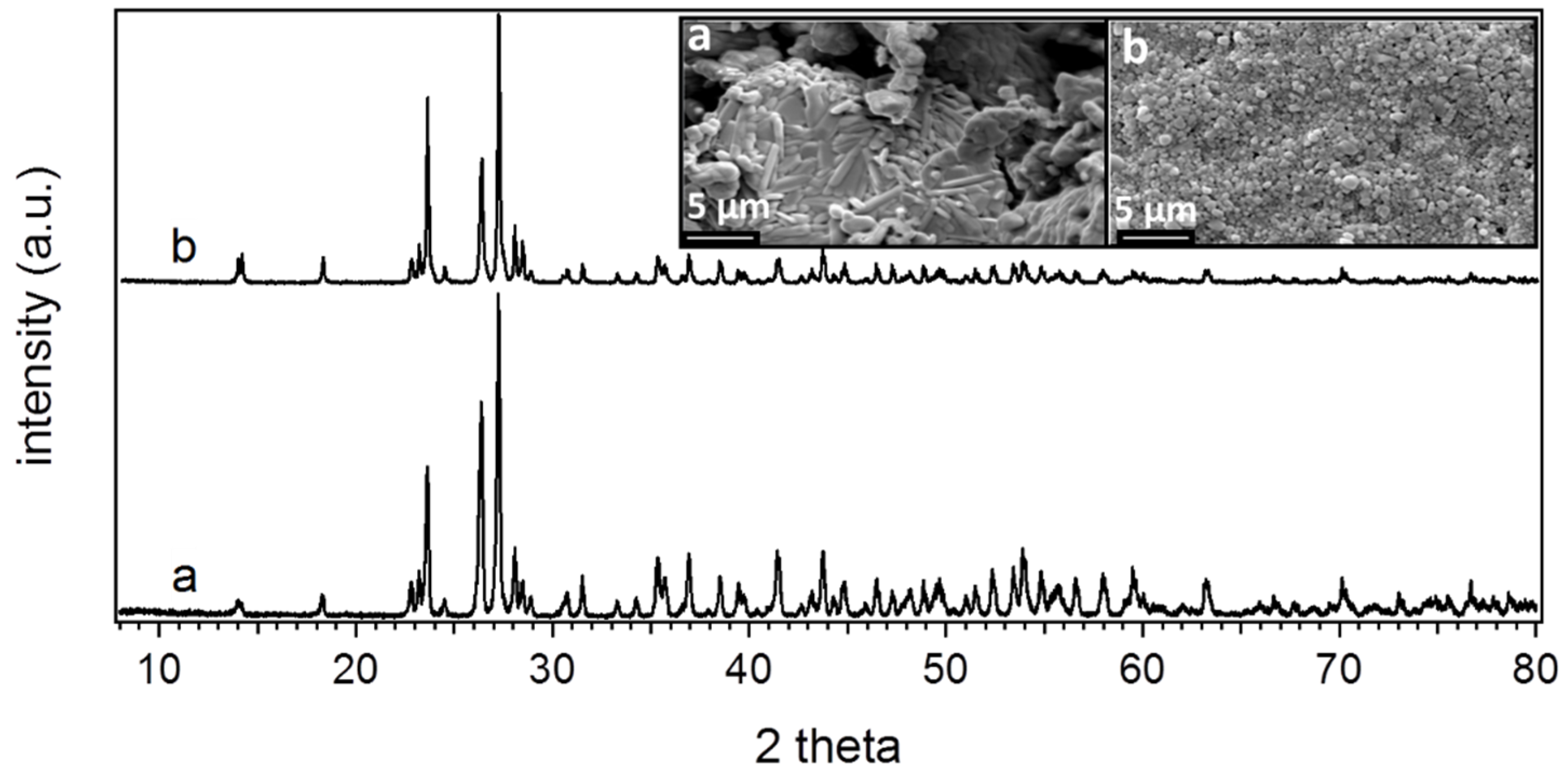
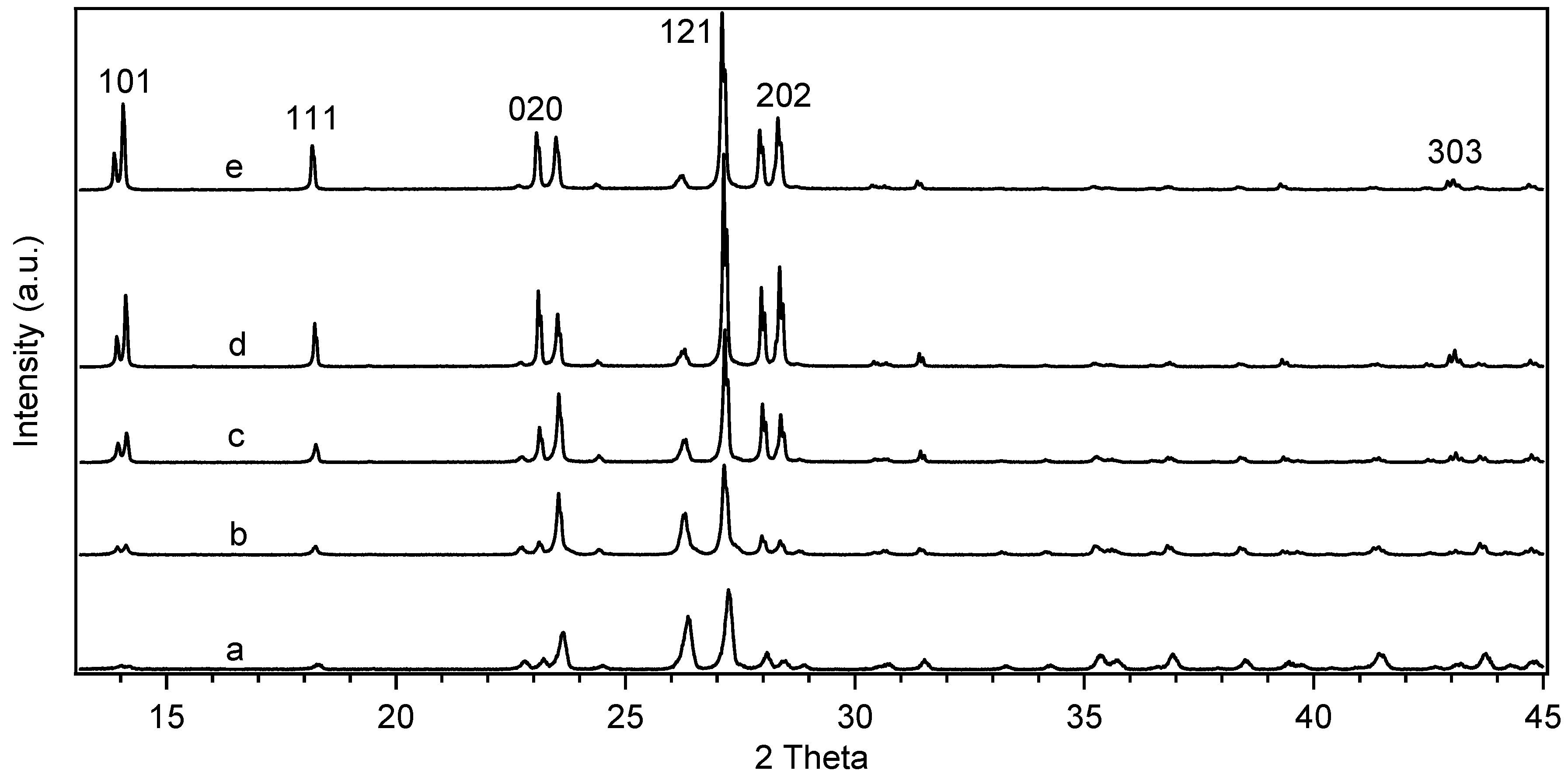
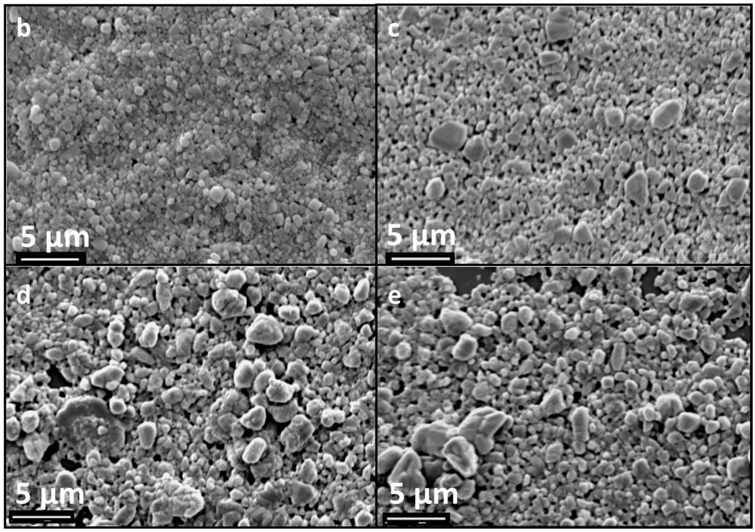
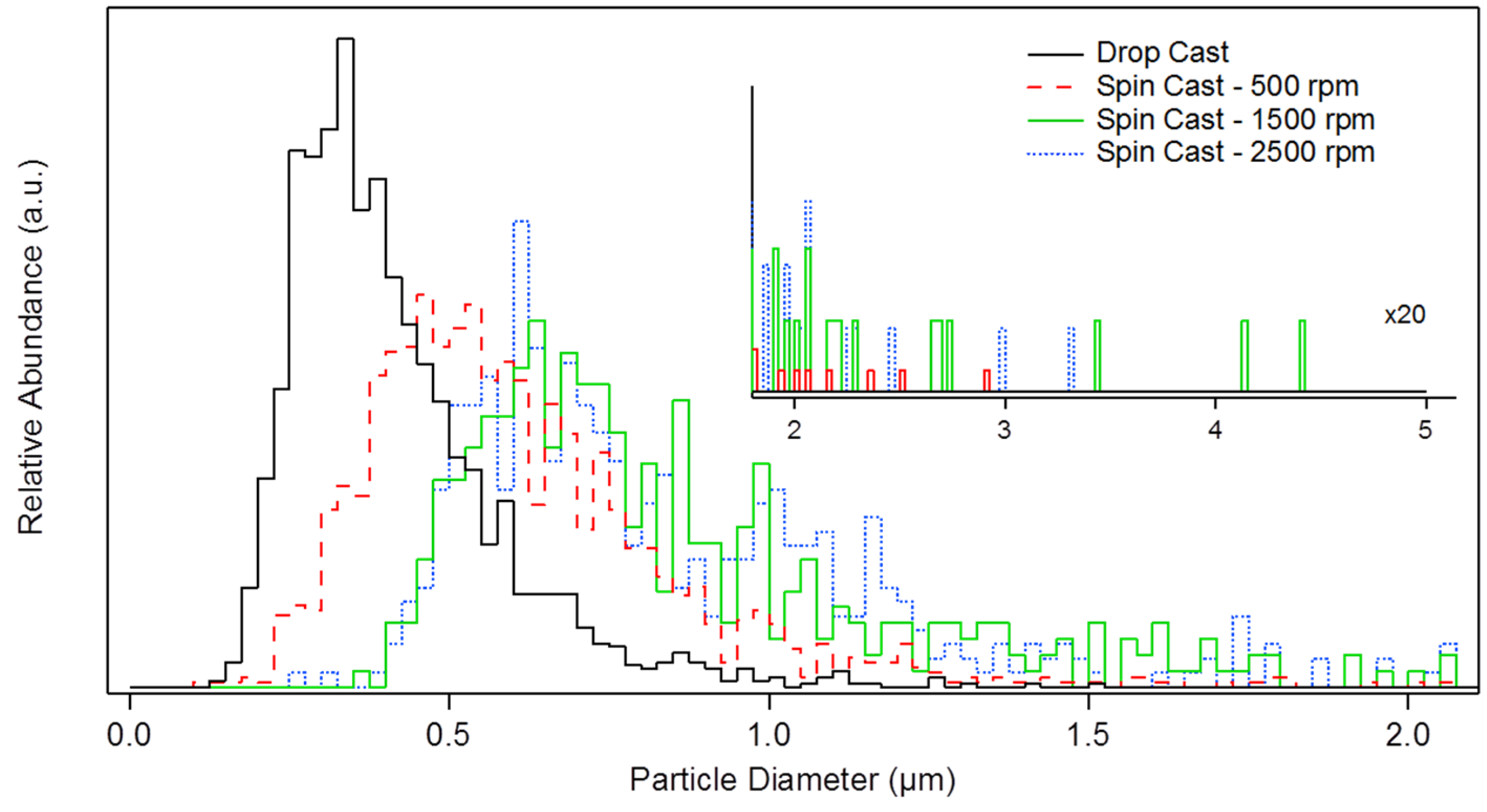
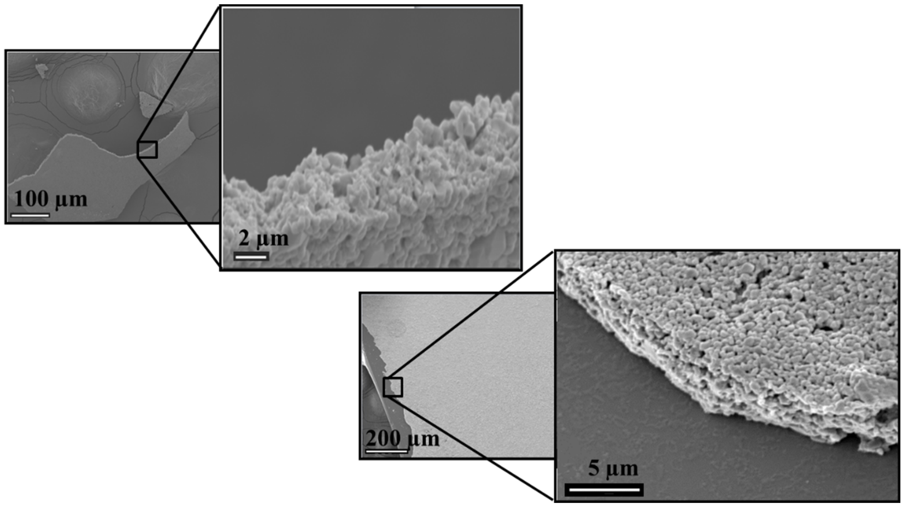
3.4. Crystallinity, Morphology and Structure of Spin-Cast Films

The dependence of the crystallinity, morphology, and structure of the particle films on spin cast samples was examined for suspensions of HI3O8 particles in denatured ethanol, and deposited at ~2% relative humidity. Sample films were produced at different spin rates—0 rpm (drop cast), 500 rpm, 1500 rpm, and 2500 rpm—and were examined by powder X-ray diffraction and scanning electron microscopy. Substrates were cleaned with methanol applied to a Kim wipe prior to deposition.
Figure 4 shows the X-ray diffractograms of the four films, all remaining in the HI3O8 hydration state with no evidence of HIO3 or I2O5 being present. As previously discussed, the drop-cast films demonstrated no significant change in the diffraction pattern from the as-received material, however, the films deposited by spin-coating exhibit an increasing preference of some diffraction peaks over others with increasing spin rate. As was seen in the high-humidity samples above, increases in intensity are observed from diffractions with Miller indices of <101>, <202> and <303>, indicating a preferential laying-down or growth of particles along their ac plane. Diffractions with indices of <111>, <020>, <121> were also enhanced with spin rate, though we note that a spin rate dependence in their intensities was not consistently observed between sample sets.
Figure 4. Powder X-ray diffractograms of HI3O8 in various forms normalized by total area: (a) HI3O8, as received material; (b) drop casted film; and (ce) spin coated films at 500 rpm, 1500 rpm, and 2500 rpm. Films were deposited at ~2% relative humidity from a sonicated suspension of the as received material in denatured ethanol.
Crystals 05 00534 g004
To examine this effect more closely, scanning electron microscopy images were recorded of each of the four films, the results shown in Figure 5. Each sample set contained 500 to 1000 particles. These images show that both the particle sizes increase significantly with spin rate and that the particle shapes become less spherical, possibly slightly more elongated. The observed particle size distributions (normalized) from these images are depicted in Figure 6, clearly showing the increase in size of the particles with spin rate. The drop cast film contains an average particle size of ~0.4 μm, whereas the highest spin rates produced material with an average particle size of ~0.9 μm. It is important to note that this change not only appears to increase the fraction of particles in the tail of the initial distribution, but also appears to reduce the amount of fine particles as the spin rate increases. This is likely due to the finer particles being washed away in carrier fluid during the spinning process.
Figure 5. Scanning electron microscopy images of deposited HI3O8 films: (b) drop casted; (ce) spin coated at 500 rpm, 1500 rpm, and 2500 rpm. Films were deposited at ~2% relative humidity from a sonicated suspension of the as-received material in denatured ethanol. Note that figure labels used here correspond to the same samples and labels shown in Figure 4.
Crystals 05 00534 g005
We attempted to quantify the degree of preferential orientation towards the ac plane of the HI3O8 particles in the films by first normalizing the integrated intensities of each diffractogram and then comparing the intensity of the <101> peak to those of the needle-like two-dimensional surface nucleated crystals (Figure 3b, assumed to be 100% oriented) and the drop cast (Figure 2b, assumed to be 0% oriented) films. The resulting calculations gave a degree of orientation 0%, 7%, 20%, and 27% for the 0, 500 rpm, 1500 rpm, and 2500 rpm spin rates, respectively. Additional films were produced with 200-proof ethanol, exhibiting nearly the same quantitative trend with spin rate. The maximum degree of preferential orientation observed in the spin cast films was 31%. It is important to emphasize, however, that the microscopy images show no evidence of two-dimensional surface nucleated induced growth, as was observed in the higher humidity samples indicating that this preferred orientation effect is most likely associated with particle movement and settling in the spin-cast process and not recrystallization/growth of the particles at the surface. This interpretation is also consistent with the images that show the particles become more elongated, a morphology that would tend to promote certain arrangements in the viscous flow during spinning. The ethanol, used here, is not very viscous and one would expect that such a working fluid would only enhance this particle size separation effect. Indeed, preferential orientations of suspended particles have been observed elsewhere for the deposition of colloids into a film by spin casting [30,52,53].
Figure 6. Apparent particle size distributions of the spin-cast films depicted in Figure 5, as obtained from electron microscope images. These HI3O8 particulate films were deposited at ~2% relative humidity from a sonicated suspension of the as received material in denatured ethanol at spin coat rates of 0 rpm (drop-cast), 500 rpm, 1500 rpm, and 2500 rpm.
Crystals 05 00534 g006
Another difference between the drop and spin-cast films appears to be that spin-casting produces a more porous film, whereas drop casting produces films of a greater density. To measure this quantitatively, each film was scratched down to the substrate and its topography measured with an optical profiler. Such measurements give a precise measure of the film thickness, which in combination with the film mass and deposits area of coverage, enable the bulk density to be estimated. The thicknesses of the various films shown in Figure 5 varied from 1.5 μm to 4 μm, but were fairly uniform across each film. This plus the mass and film size corresponds to % theoretical maximum density (%TMD) of 88%, 43%, 21%, and 40% for films cast at 0, 500, 1500, and 2500 rpm, respectively. The variability in density is quite high for the high spin rate films, but nevertheless, they exhibit approximately twice the porosity of the drop cast. This difference will likely be sensitive to the suspension particle size distributions as well as the viscosity of the solvent. Future work will examine if increasing the viscosity of the liquid media will eliminate such effects. Table 1 summarizes all of the physical properties of the films including the uncertainties of each of the measurements. It is important to note that even though five coatings were also applied to the spin cast samples at 1500 and 2500 rpm, only one layer was visible in SEM images for those films (not shown). This suggests that samples produced at higher spin rates must have exceeded an equilibrium point by which the dispersed suspension was significantly removed versus retained during spinning. Another explanation is the possibility that subsequent coatings could partially wash away or re-dissolute the underlying coating during deposition. The later effect would most likely be enhanced at higher spin rates and minimized at lower spin rates where the solvent evaporation rate is more significant. In addition, the surfaces of the films were very rough due to the increase in population of larger particles compared to samples spun at lower speed and the drop cast film. This coarseness may also explain the large variability in film thickness and %TMD across those samples. Another concern observed in samples d and e is the increase in irregularly shaped particles, and that such particles will inhibit the construction of a more closely packed structure as observed in samples b and c. This could imply limitations with the maximum spin coating thickness and 3D quality of the film to particle sizes in the submicron range although larger particle sizes have reportedly been spin coated with increased order [53]. Films spin coated at 500 rpm show signs (shown in the Supplementary Figure S4) of edge effects in the corner of the film signifying inadequate centrifugal force to spread the fluid uniformly across the substrate as compared to films coated at 1500 rpms and 2500 rpms.
Table 1. Summary of the properties of drop and spin cast films of HI3O8 particles. % Orientation is the fraction of the crystals that have their ac crystal plane oriented parallel to the surface (denatured ethanol/ethanol films).
Spin Cast RateFilm MassFilm ThicknessAvg. Particle Diameter%TMD% Orientation
(b) 0 rpm *9.9 ± 0.1 mg3.4 ± 0.4 μm (1 layer)0.41 ± 0.12 μm88 ± 4.4%0/NA
(c) 500 rpm5.8 ± 0.1 mg4.1 ± 0.7 μm ( 5 layers)0.61 ± 0.19 μm43 ± 6.6%7/15
(d) 1500 rpm2.8 ± 0.1 mg4.1 ± 0.7 μm (~1 layer)0.90 ± 0.33 μm21 ± 7.5%20/25
(e) 2500 rpm2.0 ± 0.1 mg1.5 ± 0.4 μm (~1 layer)0.86 ± 0.28 μm40 ± 11.4%26/31
* drop casted; NA = not available.
Figure 7 shows SEM images of cross-sections of two of the particulate films (b and c from Figure 5); sample b is lifted off of the substrate. The latter was produced in five layers, though the total thickness of each film was similar. The particle sizes, porosity, and packing appear to be uniform throughout the thickness of both films, though there does appear to be striations visible for each layer in the spin cast film. In agreement with the % TMD, the drop casted film features a tighter packing of particles as compared to spin cast films.
Figure 7. (Top, left) SEM image of a fragment from a drop-casted film. (bottom, right) spin coated film deposited at a rate of 500 rpm with five coatings. Films were casted from a HI3O8 suspension sonicated in denatured ethanol and deposited at ~2% relative humidity.
Crystals 05 00534 g007
Structural properties such as particle size, % TMD and thickness are known to influence the overall reactivity of an energetic film. For example, particle size distributions will affect the 3D stacking of the film as well as the porosity of the film, which is revealed in the % TMD value. Energetic films with low % TMD values would be expected to reach their maximum propagation velocity if there combustion mechanism were predominately convection driven. However, if the combustion mechanism were conduction driven, then lower % TMD films would perform poorly as compared to higher %TMD films of the same composition. Furthermore, film thickness is expected to influence the propagation behavior in the energetic material during combustion similar to the effect observed for the critical diameter of a high explosive. Therefore the “critical thickness” of an energetic film would dictate the threshold thickness for which steady state propagation is maximized and sustained for that energetic composition. Film properties in Table 1 reflect variations in film thickness and % TMD given the deposition method and presumably the average particle size. Particle orientation and the presence or absence of material layers may also reasonably affect reactivity as the thermal and gas transport properties will be different. By understanding and controlling the casting process one may explore or tune the underlying combustion mechanisms governing the reactivity of fuel and oxidizer composite films.

4. Experimental Section

4.1. Materials

I2O5 (98%) and absolute ethanol (99.5%) were purchased from Acrōs Organics (AO). “I2O5” was determined to be (>99%) HI3O8 by powder X-ray diffraction. Denatured ethanol, 2-propanol (99.5%), methanol (99.9%), acetone (99.9%), 2-butanone (99.7%), ethyl acetate (99.9%), hexane (95%), and acetonitrile (99.9%) were purchased from Sigma-Aldrich and used as-received with no effort to further purify or dry the solvents. The deionized water used had a purity of 18 MΩ.

4.2. Characterization

Scanning Electron Microscopy (SEM): images were acquired using a JEOL JSM-5900LV microscope. Samples were prepared by adhering the film to carbon tape attached to an aluminum stub. To minimize the effects of charging all samples were sputter covered with a Au/Pd (5–10 nm thick). Zeta-20 3D Optical Profiler: film thickness was determined by acquiring 7–10 scans on each sample at the film edge moving inwards, as well as across a scratch made in the middle of the films. Particle analysis: Particles in electron microscopy images were identified manually with a software macro developed in Igor Pro 6.34A which collects size, shapes and statics on the traced particles. UV-Visible spectroscopy: aliquots of samples sonicated in various alcohol/ketone/acetate mixtures were diluted with hexane and their optical spectra measured within a quartz cuvette (10 mm). Set-up consisted of a tungsten light source, two reflecting mirrors, cuvette holder (CVH100), optical fiber, and a Thorslab SP1-USB UV/visible spectrometer (400–800 nm) with a single beam collection. Spectra data presented were treated by removing the absorption intensity of the liquid medium (background) from the solution. In some cases, aliquots were centrifuged to assist in the removal of suspended crystals that could interfere with the incident beam via scattering. Powder X-ray diffraction: X-ray diffractograms were recorded with a Philips X’Pert Pro MPD spectrometer between the scan range of 2θ = 8 and 80 degrees using a Cu radiation source (Cu-Kα, λ = 1.54178 Å). Samples were rotated on a stage during the analysis and prepared by centering the powder or film on a zero background holder.

5. Conclusions

In this manuscript, we have investigated the effects of processing iodine (V) oxides particles in sonicated, ethanol-based suspensions into particulate films. Sonicating HI3O8 particles in alcohol suspensions was shown to reduce the mean size of the particles as well as increase their morphological uniformity. However, care must be taken when utilizing alcohols for processing iodine oxides as they can oxidize the solvent after long periods of time. Particles deposited at a low relative humidity were of the highest density, particle uniformity and stability. Non-uniformities amongst particle shapes were observed at higher relative humidity conditions during deposition, which is attributed to dissolution that occurs during deliquescence followed by crystal growth. Recrystallization of the solute from alcohol suspensions at relative humidity values of 40% or greater demonstrated preferred growth along the ac-plane of the crystal. Spin-coated films also reflect increased preferential growth/stacking along the ac-plane of the crystal as a function of spin rate. Drop cast films reflect no orientation effects like those seen in the spin-coated films. Surprisingly, spin-coated films above a low spin rate threshold possess only a monolayer of tightly packed particles despite multiple coatings applied during deposition, whereas spin-coated films at low spin rates feature multiple layers corresponding to the number of coatings applied. The particle size distribution are observed to shift towards larger sizes as the spin rate increases as well as does the propensity to deposit irregularly shaped particles. Drawbacks to these two deposition methods, based on these initial studies, were the instability of the drop cast film to remain anchored to the substrate during drying and that higher spin-coated films do not appear able to stack into robust 3D layered structures.
Future work will explore in greater detail the origins of single layers at high spin rates versus multiple layers at low spin rates. In addition, suspension fluids that are more resistant to oxidation by the oxidizer particle will be pursued to improve the shelf life of this process. Formulations will be optimized to improve dispersion, fluid flow and particle retention during the spin coating process in order to provide a more uniform deposited structure. Particle size effects will be investigated to determine their influence on the final deposited structure such as thickness, % TMD, layering and particle orientation given the deposition method. Finally, oxidizer based films will be doped with fuels or deposited as fuel-oxidizer films and tested for their reactivity.

Supplementary Files

Supplementary File 1

Acknowledgments

The authors wish to thank Voncile W. Ashley for her assistance in particle size analysis of SEM images. This work was supported by research grant 3002NW from the Air Force Office of Scientific Research and Program Officer Michael Berman. Distribution A. Approved for public release, distribution unlimited.

Author Contributions

Experimental work, characterization and analysis were carried out by Brian Little. Samuel Emery and Michael Lindsay assisted in the design and analysis of experiments, experimentation, as well as the writing of this manuscript.

Conflicts of Interest

The authors declare no conflict of interest.

References and Notes

  1. Martirosyan, K.S. Nanoenergetic gas-generators: Principles and applications. J. Mater. Chem. 2011, 21, 9400–9405. [Google Scholar] [CrossRef]
  2. Russell, R.; Bless, S.; Pantoya, M. Impact-driven thermite reactions with iodine pentoxide and silver oxide. J. Energ. Mater. 2011, 29, 175–192. [Google Scholar] [CrossRef]
  3. Jenkins, C.M.; Horie, Y.; Lindsay, C.M.; Butler, G.C.; Lambert, D.; Welle, E.J. Cylindrical converging shock initiation of reactive materials. In Shock Compression of Condensed Matter–2011, Proceedings of the American Physical Society Topical Group on Shock Compression of Condensed Matter, Chicago, IL, USA, 26 June–1 July 2011; AIP Publishing: College Park, MD, USA, 2012; Volume 1426, pp. 197–200. [Google Scholar]
  4. Ivanov, V.G.; Ivanov, G.V.; Lapin, P.V.; Kuznetsov, V.P. Role of iodation in the combustion of metal oxides with iodine pentoxide. Combust. Explos. Shock Waves 1981, 17, 607–614. [Google Scholar] [CrossRef]
  5. Little, B.K.; Avjian, E.K.; Bogle, M.; Nittinger, J.C.; Emery, S.B.; Schrand, A.; Lindsay, C.M. Trade-off between sensitivity and performance in nano-aluminum/iodine (V) oxide, joint army navy NASA air force. In Proceedings of the 38th Propellant and Explosives Development and Characterization Meeting, Monterey, CA, USA, 3–6 December 2012.
  6. Sherwood, P.M.A.; Turner, J.J. Mass spectrum of iodine pentoxide and a novel reaction with copper. J. Chem. Soc. A Inorg. Phys. Theor. 1970, 2349–2350. [Google Scholar] [CrossRef]
  7. Clark, B.R.; Pantoya, M.L. The aluminum and iodine pentoxide reaction for the destruction of spore forming bacteria. Phys. Chem. Chem. Phys. 2010, 12, 12653–12657. [Google Scholar] [CrossRef] [PubMed]
  8. Little, B.K.; Emery, S.B.; Nittinger, J.C.; Fantasia, R.C.; Lindsay, C.M. Physiochemical characterization of Iodine (V) oxide, part 1: Hydration rates. J. Propellants Explos. Pyrotech. 2014, 35, 1–10. [Google Scholar] [CrossRef]
  9. Selte, K.; Kjekshus, A. Iodine oxides part II: On the system H2O-I2O5. Acta Chem. Scand. 1968, 22, 3309–3320. [Google Scholar] [CrossRef]
  10. Kumar, R.; Saunders, R.W.; Mahajan, A.S.; Plane, J.M.; Murray, B.J. Physical properties of iodate solutions and the deliquescence of crystalline I2O5 and HIO3. Atmos. Chem. Phys. Discuss. 2010, 10, 20823–20856. [Google Scholar] [CrossRef]
  11. Little, B.K. Observations made in the laboratory.
  12. Rossie, C.; Zhang, K.; Estève, D.; Alphonse, P.; Tailhades, P.; Vahlas, C.J. Nanoenergetic materials for MEMS: A review. J. Microelectromech. Syst. 2007, 16, 919–931. [Google Scholar] [CrossRef] [Green Version]
  13. Manesh, N.A.; Basu, S.; Kumar, R. Experimental flame speed in multi-layered nano-energetic materials. Combust. Flame 2010, 157, 476–480. [Google Scholar] [CrossRef]
  14. Ding, M.S.; Krieger, F.C.; Swank, J.A. Developing NanoFoil-Heated Thin-Film Thermal Battery. Available online: http://oai.dtic.mil/oai/oai?verb=getRecord&metadataPrefix=html&identifier=ADA586188 (accessed on 16 September 2015).
  15. Barron, S.C.; Knepper, R.; Walker, N.; Weihs, T.P. Characterization of self-propagating formation reactions in Ni/Zr multilayered foils using reaction heats, velocities, and temperature-time profiles. J. Appl. Phys. 2011, 109. [Google Scholar] [CrossRef]
  16. Trenkle, J.C.; Koerner, L.J.; Tate, M.W.; Gruner, S.M.; Weihs, T.P.; Hufnagel, T.C. Phase transformation during rapid heating of Al/Ni multilayer foils. Appl. Phys. Lett. 2008, 93. [Google Scholar] [CrossRef]
  17. Weihs, T.P.; Barmack, K.; Coffey, K. Fabrication and characterization of reactive multilayer films and foils. In Metallica Films for Electronic, Optical and Magnetic Applications: Structure, Processing and Properties; Woodhead Publishing Limited: Philadelphia, PA, USA, 2014; pp. 160–243. [Google Scholar]
  18. Dlott, D.D. Thinking Big (and Small) about Energetic Materials. Mater. Sci. Technol. 2006, 22, 463–473. [Google Scholar] [CrossRef]
  19. Prakash, A.; McCormick, A.V.; Zachariah, M.R. Thermo-kinetic study of core-shell Nanothermites. In Shock Compression of Condensed Matter–2005, Proceedings of the Conference of the American Physical Society Topical Group on Shock Compression of Condensed Matter, Baltimore, MD, USA, 31 July–5 August 2005; pp. 1006–1009.
  20. Prakash, A.; McCormick, A.V.; Zachariah, M.R. Tuning the reactivity of energetic nanoparticles by creation of a core-shell nanostructure. Nano Lett. 2005, 5, 1357–1360. [Google Scholar] [CrossRef] [PubMed]
  21. Jingyu, F.; Guoqiang, J.; Qing, L.; Zachariah, M.R. Passivated iodine pentoxide oxidizer for potential biocidal nanoenergetic applications. ACS Appl. Mater. Interfaces 2013, 5, 8875–8880. [Google Scholar]
  22. Emery, S.; Rider, K.B.; Lindsay, C.M. Stabilized Magnesium/Perfluoropolyether Nanocomposite Films by Helium Droplet Cluster Assembly. Propellants Explos. Pyrotech. 2014, 39, 161–165. [Google Scholar] [CrossRef]
  23. Becker, C.R.; Currano, L.J.; Churaman, W.A.; Stoldt, C.R. Thermal analysis of the exothermic reaction between galvanic porous silicon and sodium perchlorate. ACS Appl. Mater. Interfaces 2010, 2, 2998–3003. [Google Scholar] [CrossRef] [PubMed]
  24. Sullivan, K.T.; Zhu, C.; Tanaka, D.J.; Kuntz, J.D.; Duoss, E.B.; Gash, A.E. Electrophoretic deposition of thermites onto micro-engineered electrodes prepared by direct-ink writing. J. Phys. Chem. B 2013, 117, 1686–1693. [Google Scholar] [CrossRef] [PubMed]
  25. Huang, C.; Jian, G.; DeLisio, J.B.; Wang, H.; Zachariah, M.R. Electrospray deposition of energetic polymer nanocomposites with high mass particle loadings: A prelude to 3D printing of rocket motors. Adv. Eng. Mater. 2015, 17, 95–101. [Google Scholar] [CrossRef]
  26. Patel, V.K.; Ganguli, A.; Kant, R.; Battacharya, S. Micropatterning of nanoenergetic films of Bi2O3/Al for pyrotechnics. RSC Adv. 2015, 5, 14967–14973. [Google Scholar] [CrossRef]
  27. Torrey, J.D.; Kirschling, T.L.; Greenlee, L.F. Processing and characterization of nanoparticle coatings for quartz crystal microbalance measurements. J. Res. Nat. Inst. Stand. Technol. 2015, 120, 1–10. [Google Scholar] [CrossRef]
  28. Panigrahi, S.; Waugh, S.; Rout, S.K.; Hassan, A.K. Ray study of spin coated organic thin film under spectrophotometer. Indian J. Phys. 2004, 78, 823–826. [Google Scholar]
  29. Larson, R.G.; Rehg, T.J. Spin coating. In Liquid Film Coating: Scientific Principles and Their Technological Implications; Kistler, S.F., Schweizer, P.M., Eds.; Chapman & Hall: London, UK, 1997; pp. 709–734. [Google Scholar]
  30. Pichumani, M.; Bagheri, P.; Poduska, K.M.; González-Vinas, W.; Yethiraj, A. Dynamics, crystallization and structures in colloid spin coating. Soft Matter 2013, 9, 3220–3229. [Google Scholar] [CrossRef]
  31. Leventis, N.; Chandrasekaran, N.; Sadekar, A.G.; Sotiriou-Leventis, C.; Lu, H. One-Pot synthesis of interpenetrating inorganic/organic networks of CuO/resocinol-formaldehyde aerogels: Nanostructured energetic materials. J. Am. Chem. Soc. 2009, 131, 4576–4577. [Google Scholar] [CrossRef] [PubMed]
  32. Hossain, M.; Subramanian, S.; Bhattacharya, S.; Gao, Y.; Apperson, S.; Shende, R.; Guha, S.; Arif, M.; Bai, M.; Gangopadhyay, K.; et al. Crystallization of amorphous silicon by self-propagation of nanoengineered thermites. J. Appl. Phys. 2007, 101. [Google Scholar] [CrossRef]
  33. Apperson, S.; Bhattacharya, S.; Gao, Y.; Subramanian, S.; Hasan, S.; Hossain, M.; Shende, R.V.; Redner, P.; Kapoor, D.; Nicolich, S.; et al. On-Chip initiation and burn rate measurements of thermite energetic reactions. MRS Proc. 2006, 896. [Google Scholar] [CrossRef]
  34. Sullivan, K.T.; Kuntz, J.D.; Gash, A.E. Fine patterning of thermites for mechanistic studies and microenergetic applications. Int. J. Energ. Mater. Chem. Propuls. 2013, 12, 511–528. [Google Scholar] [CrossRef]
  35. Thiruvengadathan, R.; Bezmelnitsyn, A.; Apperson, S.J.; Tappmeyer, D.; Redner, P.; Balas, W.A.; Nicolich, S.; Kapoor, D.; Gangopadhyay, K.; Gangopadhyay, S. Combustion behavior of nanoenergetic material systems. In Energetic Materials: Thermophyscial Properties, Predictions, and Experimental Measurements; Boddu, V., Redner, P., Eds.; CRC Press: Boca Raton, FL, USA, 2010; pp. 239–262. [Google Scholar]
  36. Plummer, A.; Kuznetsov, V.; Joyner, T.; Shapter, J.; Voelcker, N.H. The burning rate of energetic films on nanostructured porous silicon. Small 2011, 7, 3392–3398. [Google Scholar] [CrossRef] [PubMed]
  37. Eapen, B.Z.; Hoffmann, V.K.; Schoenitz, M.; Dreizin, E.L. Combustion of aerosolized spherical Al powders and flakes in air. Combust. Sci. Technol. 2010, 176, 1055–1069. [Google Scholar] [CrossRef]
  38. Rider, K.B.; Little, B.K.; Emery, S.B.; Lindsay, C.M. Thermal analysis of magnesium/perfluoropolyether pyrolants. Propellants Explos. Pyrotech. 2013, 38, 433–440. [Google Scholar] [CrossRef]
  39. Shaw, W.L.; Dlott, D.D.; Williams, R.A.; Dreizin, E.L. Ignition of nanocomposite thermites by electric spark and shock wave. Propellants Explos. Pyrotech. 2014, 39, 444–453. [Google Scholar] [CrossRef]
  40. Hamons, J.A.; Wang, W.; Ilavsky, J.; Pantoya, M.; Weeks, B.; Vaugh, M.W. Small angle X-ray scattering analysis of the effect of cold compaction of Al/MoO3 thermite composites. Phys. Chem. Chem. Phys. 2008, 10, 193–199. [Google Scholar] [CrossRef] [PubMed]
  41. Yen, N.H.; Wang, L.Y. Reactive Metals in Explosives. Propellants Explos. Pyrotech. 2012, 37, 143–155. [Google Scholar] [CrossRef]
  42. Luque de Castro, M.D.; Priego-Capote, F. Ultrasound-assisted Crystallization (Sonocrystallization). Ultrason. Sonochem. 2007, 14, 717–724. [Google Scholar] [CrossRef] [PubMed]
  43. Ruecroft, G.; Hipkiss, D.; Ly, T.; Maxted, N.; Cains, W. Sonocrystallization: The Use of Ultrasound for Improved Industrial Crystallization. Org. Process. Res. Dev. 2005, 9, 923–932. [Google Scholar] [CrossRef]
  44. Suslick, K.S. Sonochemistry. Science 1990, 247, 1439–1442. [Google Scholar] [CrossRef] [PubMed]
  45. Hayes, W.M. CRC Handbook of Chemistry and Physics, 96th ed.; CRC Press: Boca Raton, FL, USA, 2015. [Google Scholar]
  46. Lebedkin, S.F.; Klimov, A.D. Quantum Yield Wavelength Dependence of Iodine Photodissociation in Hexane and Benzene Studied by the Time-Resolved Thermal Lens Methods. Chem. Phys. Lett. 1992, 190, 313–314. [Google Scholar] [CrossRef]
  47. Lapworth, A. The effect of halogens on compounds, which contain the carbonyl group. J. Chem. Soc. 1904, 85, 30–42. [Google Scholar] [CrossRef]
  48. Morrison, R.T.; Boyd, R.N. Organic Chemistry, 5th ed.; Allyn and Bacon, Inc.: Boston, MA, USA, 1987; pp. 912–913. [Google Scholar]
  49. Drugfuture.com—Iodine Pentoxide. Available online: http:://www.drugfuture.com/chemdata/iodine-pentoxide.html (accessed on 8 August 2015).
  50. Bray, W.C.; Lamb, A.B. Process of Bearing Iodic Acid. U.S. Patent 151938, 17 July 1922. [Google Scholar]
  51. Fischer, A. Redetermination of HI3O8, an adduct of formula HIO3•I2O5. Acta Cryst. Sec. E 2005, 61, 278–279. [Google Scholar] [CrossRef]
  52. Mihi, A.; Ocana, M.; Miguez, H. Oriented collodidal-crystal thin films by spin-coating microspheres dispersed in volatile media. Adv. Mater. 2006, 18, 2244–2229. [Google Scholar] [CrossRef]
  53. Toolan, T.W.; Fuji, S.; Ebbens, S.J.; Nakamura, Y.; Howse, J.R. On the Mechanisms of Colloidal Self-Assembly During Spin-Coating. Soft Matter 2014, 10, 8804–8812. [Google Scholar] [CrossRef] [PubMed]

