
Formation Mechanism of CaCO3 Spherulites in the Myostracum Layer of Limpet Shells


EaStCHEM, School of Chemistry, University of St Andrews, Fife KY16 9ST, UK
*
Author to whom correspondence should be addressed.
Crystals 2017, 7(10), 319; https://doi.org/10.3390/cryst7100319
Submission received: 14 August 2017
/
Revised: 16 October 2017
/
Accepted: 16 October 2017
/
Published: 23 October 2017
(This article belongs to the Special Issue Biological and Biogenic Crystallization)
Abstract
:CaCO3 spherulites were found in the myostracum layer of common limpet shells collected from East Sands, St Andrews, Scotland. Their microstructures were revealed by using powder X-ray diffraction, scanning electron microscopy, high-resolution transmission electron microscopy, and energy dispersive X-ray microanalysis. The formation mechanisms of these spherulites and their morphology evolution were postulated. It was proposed that spherical particles of an inorganic and biological composite formed first. In the centre of each spherical particle a double-layer disk of vaterite crystal sandwiching a biological sheet developed. The disk crystal supplies a relatively strong mirror symmetric dipole field, guiding the orientations of the nanocrystallites and the arrangement of mesorods and, therefore, determining the final morphology of the spherulite.
1. Introduction
Calcium carbonate is largely found in natural creatures, especially marine organisms, such as echinoderms, abalone, and sea molluscs [1,2]. These parts of inorganic-organic composites often function as body supports, e.g., exoskeletons, to protect the creatures from injury, or form shelters to offer themselves a safe living environment. Unlike relatively regular artificial crystals, CaCO3 crystals in biological systems present very complicated morphologies, e.g., the aragonite nanoplates in nacre [3], the complex structure of coccolithophores [4], calcite spines of sea urchins [5], etc., which seem to be perfectly pre-designed and are rarely reproduced by using any advanced biomimetic methods in the laboratory. It is, therefore, of great interest to reveal detailed processes of crystal growth and to understand crucial factors which control the crystal growth in natural creatures.
Crystalline CaCO3 exists as one of three principal anhydrous polymorphs, i.e., calcite (rhombohedral), aragonite (orthorhombic), and vaterite (hexagonal). According to the phase diagram of pure calcium carbonate, calcite has been proved to be the most thermodynamically stable phase, and vaterite, the least [6]. Vaterite would transform into a more stable polymorph upon contact with water [7], e.g., converting to calcite at low temperature and to aragonite at high temperature. However, in some special conditions, the stabilities of these three polymorphs can alternate. For example, Mg substitution in calcite may greatly reduce its stability, leading to a transformation to aragonite [8].
In nature creatures, CaCO3 microcrystals are commonly embedded in a biological matrix and both aragonite and vaterite can be the stable phases. For example, aragonite is included in many marine biominerals, such as nacreous tablets [9,10,11,12], urchin spines [5,13], and crossed lamellae in seashells [14]. Metastable vaterite can also exist in the natural productions and biomineralization. According to the research of Soldati et al. [15] and Wehrmeister et al. [16], both vaterite and aragonite were detected in freshwater cultured pearls, and vaterite was observed to exist in an aragonite environment. In Ascidiacea, known as sea squirts, vaterite also exists in form of spicules [17].
In addition to these crystalline phases, in many biomineralization processes, amorphous calcium carbonate (ACC), as a precursor of crystalline CaCO3, plays an important role in the formation of crystalline phases and crystal morphologies. In a simple environment, ACC can transform to aragonite at high temperature (over 40 °C) and to calcite at low temperature [18,19].
Spherulite is probably one of the most interesting morphologies found in natural creatures or biominerals, because their nature of the inorganic and biological composite and their radial crystal orientations. Spherulites were found in a wide range of materials, in addition to the common carbonates, for instance, polymers [20], metals [21], and organic molecules [22]. Spherulites have also attracted increasing attention from geologists [23,24,25], because carbonate spherulites have high porosity and permeability and are excellent reservoirs in pre-salt fields. In the last decades, several key factors of forming spherulites have been proposed, including Brownian motion, phase field effect, and dipole field interaction.
Spherulites can form via aggregation of tiny nanocrystallites (<10 nm) in Brownian motion [26]. However, the detailed microstructures and complicated morphologies of spherulites cannot be explained simply using Brownain motion. The phase field effect was believed to be a more convincing explanation of the spherulitic growth [27]. According to the previous research, the spherulites were divided into two categories: (1) spherulites grow in a radial manner from a nucleus and more branches intermittently filled the space during the growth; and (2) threadlike particles grow first and new grains formed at the growth front. By splaying out the branching on both ends, a spherical morphology was achieved. In this process, two characteristic “eyes” were developed on each side of the core region [27]. The phase field, as is claimed to be the driving force of the spherulite formation, was based on the “diffusional instabilities”. The model indicated a competition between the ordering effect of discrete local crystallographic symmetries and the randomization of the local crystallographic orientation with growth front nucleation. In 2000, Banfield et al. [28] revealed a three-dimensional rotation of nanoparticles in their HRTEM study of natural iron oxyhydroxide biomineralization products. Neighbouring nanoparticles could aggregate and rotate to adopt parallel orientations.
According to many published papers, some elements, such as magnesium, can not only affect the stability of the crystalline CaCO3, but also play important roles in the formation of spherulitic morphology. Tracy et al. reported that co-existence of Mg2+ and SO42− ions allowed a formation of spherulites of CaCO3 [29,30]. ACC was also found to be important to the formation of novel morphologies, in addition to working as a transient precursor for crystalline phases of CaCO3 [31]. It is quite interesting to see that, in biological systems, some organisms can produce unusually stable hydrated ACC, as reported by Addadi et al. [32]. The hydration of ACC would inevitably affected by pH in the solution [33]. The crystallization process of ACC in biomineralization was also investigated by using an in situ small- and wide-angle X-ray scattering (SAXS/WAXS) method, and a multi-step evolution was discovered, i.e., formation in order of hydrated and disordered ACC, more ordered and dehydrated ACC, ACC dissolution and spherulitic growth of vaterite, and Ostwald ripening of the vaterite [34].
The addition of organic compounds in a synthetic system can enhance the formation of spherulitic morphology of CaCO3. For example, hollow spherulites of calcite crystals would precipitate in the presence of alginates [35]. Biological matter is even better. Rodriguez-Navarro et al. believed that bacterical production of CO2 and NH3, and the transformation of the latter to OH−, led to the growth of vaterite crystallites on bacterial cells, or the so-called extracellular polymeric substance (EPS), to form spherulites [36]. Greer et al. [37] also observed such a phenomenon in a synthesis of biomimetic vateritic hexagonal prisms with gelatine, and further found that the electrical dipole field interaction between the crystallites was the driving force for aggregation and self-orientation. In other words, the nanocrystallites were regarded as dipoles and, because of the interaction with the central dipole field, the nanocrystallites embedded in a soft matter matrix could rotate and self-arrange in an unusual way.
There is another common argument of whether the spherulites of CaCO3 grow directly from solution by central multidirectional growth or by aggregation of nano-sized precursor crystals. Andreassen and co-workers made a significant effort and found that the former is more likely the true mechanism [38,39]. This conclusion is probably correct for some spherulites, such as the particles constructed by a single layer of radiating nanorods [40]. However, it may face a challenge in explaining the formation of spherulites with multiple layers of short nanorods. Further evidence is needed from HRTEM images of the specimens at intermediate stages of growth.
In the present work, spherulites found in limpet shells are investigated chiefly by using electron microscopy. Some interesting microstructures have been observed, e.g., a core rich in biological matter, multilayer short nanorods, possible evolution of the microstructures, etc. A dipole field-driven formation mechanism of the hierarchical structure of these calcium carbonate mesospherulites is proposed. Spherulites formed in a natural environment and synthesized in the laboratory, as presented in a previously-published report [37], are compared in order to shed light to the future biomimetic synthesis of crystals with various morphologies.
2. Results
Live limpet samples were collected at East Sands, St Andrews, Scotland (Figure 1a). According to SEM observations, a limpet shell consists of six layers (M − 2, M − 1, M, M + 1, M + 2, M + 3, from inner to outer sides), as illustrated in Figure 1c. Spherulites about 100 μm in diameter were only found in the M layer (abbreviation of myostracum) (Figure 1b). There is an equatorial notch at the centre of each spherulite, dividing the whole particle into two hemispheres, which was the first sign that aroused our curiosity.
SEM images of whole spherulites show a rough surface (Figure 2a). Examinations of the exterior and near surface area of the spherulites reveal that the outer layer of the particles is formed by radially-located mesorods, which have a shape of a hexagonal prism with about 1.5–5 μm in width and 20 μm in length, sticking out from the centre of the particles (Figure 2b). On the side surface of the hexagonal prisms, multiple nanosheets grow from the bottom as coating skins, indicating that the starting point of the growth is at the bottom ends of the mesorods and the mesorods have a high crystallinity. Similarly, aragonite crystal mesorods were synthesized by Zhou et al. and Nan et al. [41,42].
The equatorial notches on the spherulites are not only a surface structural feature, but evidence of cracks cross to the particle cores. Figure 2c shows a SEM image of a cross-section of spherulite, revealing the microstructure in the central area of the particle. It is noted that the crack starts from a small disk (~4 μm in diameter) at the centre of a core, which is about 15 μm in diameter. The spherical core is separated into two hemispheres by the smaller disk, which seems to have a sandwich shape (see inset of Figure 2c).
Figure 2d shows a SEM cross-section image of another spherulite, which is also supposed to be at an early stage of growth because of the small size and the relatively poor ordering of the nanoparticles. In particular, radiating mesorods have not formed in the surrounding areas, marked D. It can be seen that the profile view of the central disk shows a multi-layer structure, i.e., a plate sandwiched by two layers (B). The central plate (elliptical shape in a profile view marked by A), about 1.1 μm in thickness and 4 μm in diameter, likely contains only biological substances, rather than Ca-containing inorganic molecules, as judged from the dark image contrast. A similar area was examined by using EDX to be Ca poor and carbon rich (see Figure 6 below). The two adjacent layers marked by B, 2.5 μm in thickness and 15 μm in diameter, show possible CaCO3 crystals. Outside of layer B formed another layer marked by C, in which radially-ordered traces can be seen, implying that nanocrystallites in this layer have self-orientated, probably guided by the central disk. Outside of layer C, in the regions marked by D, there are many parallel, short, needle-like particles lying along a direction which seems to have no special relation with the mesorods in the central area. This area seems to be less affected by the central disk.
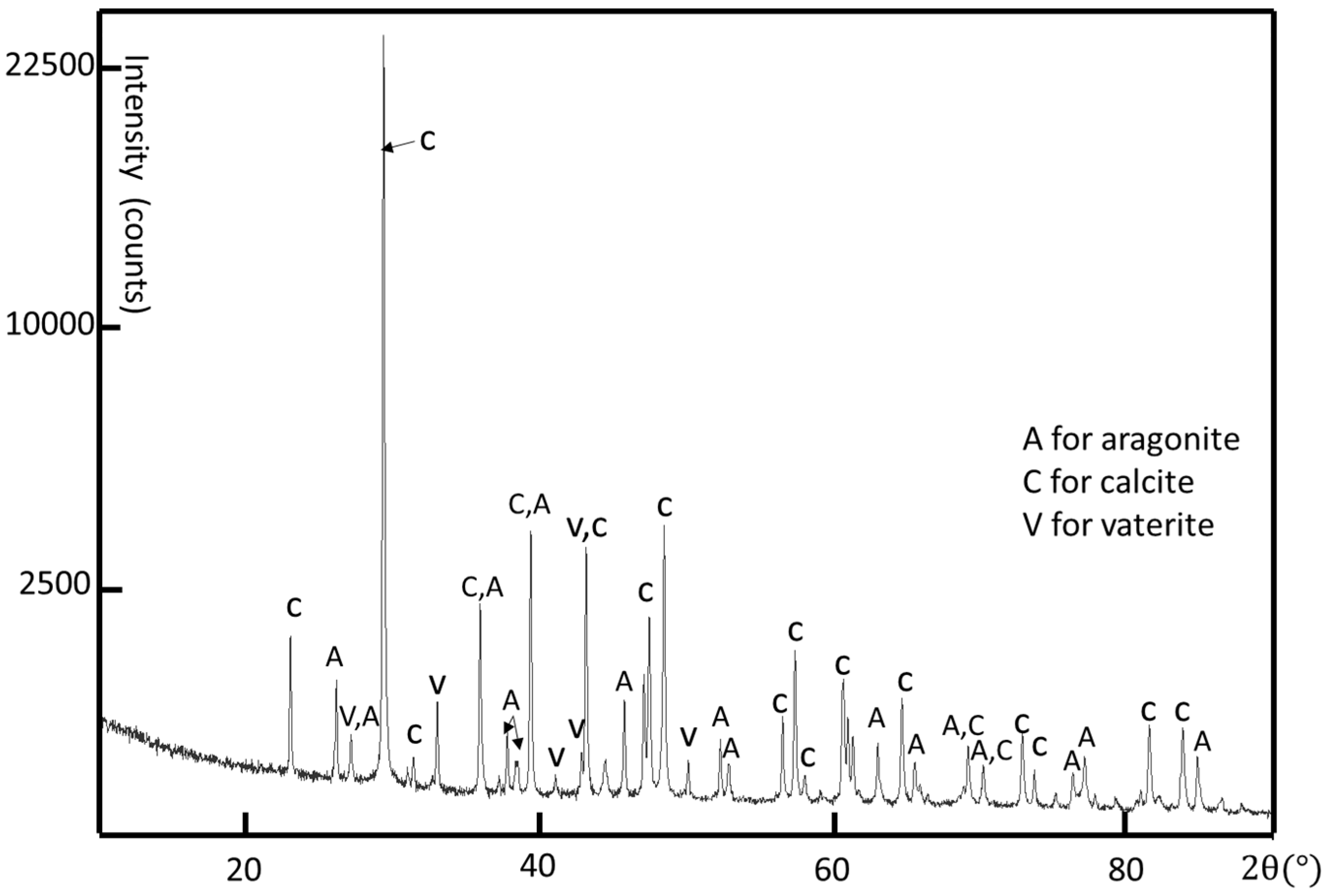
Although the crystal structure of individual crystallites can be determined by using selected area electron diffraction (SAED) patterns and high-resolution transmission electron microscopy (HRTEM) images, powder X-ray diffraction (XRD) is used to determine all possible crystalline phases in the whole shell. A limpet shell was ground into powder for XRD analysis. According to the XRD result shown in Figure 3, all three common phases of calcium carbonate, i.e., calcite, aragonite, and vaterite, are detected. The major crystalline phases are calcite and aragonite. The calcite phase has a rhombohedral structure with a = 4.98 Å, c = 17.07 Å, space group R-3c (JCPDS card no. 01-080-9776) and the aragonite phase is orthorhombic with a = 4.97 Å, b = 7.96 Å, c = 5.75 Å, space group Pmcn (JCPDS card no. 01-075-9984). There are some small peaks confirming the existence of hexagonal vaterite as a minor phase in the limpet shell with the unit cell parameters a = 4.13 Å, c = 8.49 Å, space group P63/mmc (JCPDS card no. 24-0030 [43]).
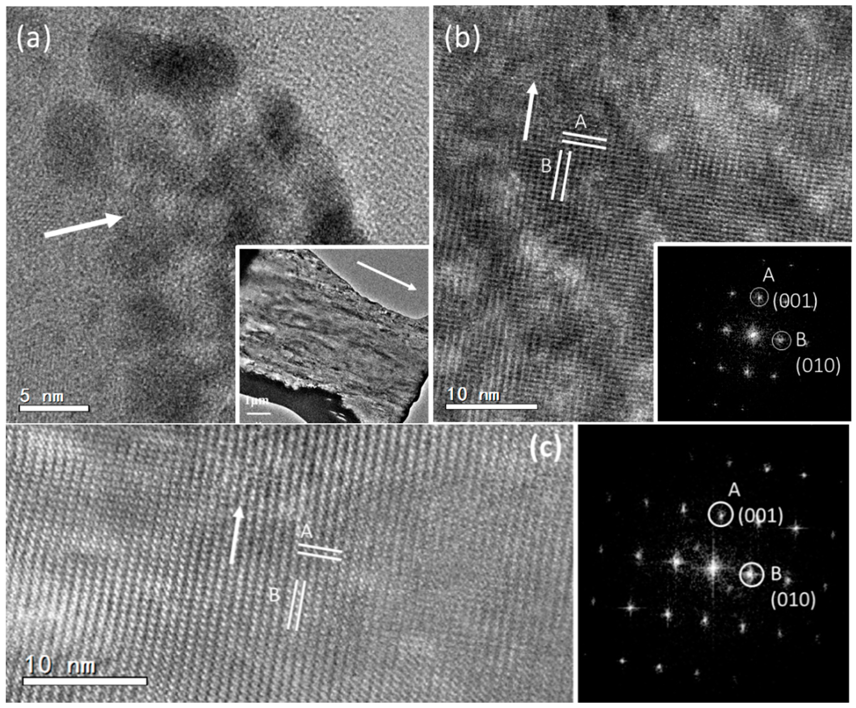
To explore the structure of the mesorods in the spherulites, a focused ion beam (FIB) technique was used to prepare samples of mesorods for the HRTEM study. A slice of a mesorod 200 nm in thickness and 15 μm in length along the long axis was cut out. Differing from the expected high crystallinity and uniform thickness, low-magnification transmission electron microscopy (TEM) images of the mesorod show a flocculent image contrast pattern, implying a large number of defects (Inset of Figure 4a). HRTEM images reveal that the surface area of the mesorod has a poor crystallinity, containing many nanocrystallites embedded in an amorphous matrix (Figure 4a). These nanocrystallites are randomly orientated.
In an inner area shown in Figure 4b, nanocrystallites are also recognized. However, they are all self-orientated and connected. The corresponding FFT pattern looks like a type of single crystal. Moving towards the centre of the mesorod, high crystallinity regions can be found, as shown in Figure 4c. The crystal orientations of the regions in Figure 4b,c are the same. A SAED pattern, recorded from a large area of this sample covering both polycrystalline region and high crystallinity region, is similar to the FFT patterns (Figure S1 in Supplementary Information). The two principal d-spacings are measured from the HRTEM images in Figure 4b,c, dA = 5.73 Å and dB = 7.95 Å, with an interplane angle of 90°, which can be indexed to the (001) and (010) planes of the aragonite structure. It is also confirmed that the longitudinal axis of the mesorod is parallel to the [001] zone axis of aragonite. According to the space group Pmcn of aragonite, the (001) and (010) diffraction spots should be systematically absent. Their appearance can be attributed to multiple scattering. However, lattice distortion lowering the symmetry of the aragonite structure cannot be ruled out.
Some spherulite particles (as shown in Figure 5) are elliptical with a relatively smooth surface (denser), but without a visible notch. To gain more information of their inner structures, it is essential to have an insight of the cross-section. The particles were cut into halves and the newly-exposed surfaces were polished. A cross-section SEM image of a typical spherulite is shown in Figure 5a. The spherulite is not a perfect spherical particle. The notch in the middle can still be recognized, although it is difficult to see from outside. The notch extends through the spherulite and separates the spherulite into symmetrical hemispheres. Along the notch, the particle becomes “thin” with a waist and looks like a short dumbbell. On the other hand, the spherulite shown in Figure 5b has no obvious notch at all, although a similar dumbbell-like core is maintained.
The hierarchical structure of the spherulites can be described as multi-layer spherical particles and over 10 distinguished layers can be detected in each spherulite (Figure 5a,b). One micrometre-wide low-density gaps are presented in between the layers (Figure 5c). The layer thickness gets smaller when the layer is closer to the core.
These layers are formed with mesorods, which are all in a radial arrangement. The diameter of the mesorods also decreases when they are closer to the core (Figure 5c). The enlarged SEM image of individual mesorods show that the mesorods in inner layers do not have a regular hexagonal morphology, as we observed from the mesorods in an outer layer (see Figure 2b). The relatively thin mesorods seem to have a polymer-like coating layer, referring to the morphology, which likely consists of biological substances. There is also a gap between the mesorods, making the layer highly porous.
The core structure must be crucial in constructing the microstructures of spherulites. Most particles have a double-hemisphere core. The first image in Figure 6 is a SEM image of a half spherulite. The image contrast in the two hemispheres separated by a double-layer disk particle is significantly darker than other parts, implying that these areas contain light elements or have a low density. Elemental mapping shows that the carbon map is brighter than calcium and oxygen, and the Ca and O concentrations are very low in these double-hemispherical areas in the core, further indicating that these areas contain less CaCO3, but rich in organic materials (Figure 6). This structure is quite different from that in Figure 2d, where only one biomass rich area is present, i.e., the central plate inside the double-layer disk.
It is believed that the core particles control the morphology and hierarchical structures of the spherulites. To fully understand the formation of the cores, it is useful to look at the cores in early ages when they are small and have a low crystallinity. The particles shown in Figure 7 are probably some examples of these core particles and surroundings. Such an assumption has to be made since we are unable to observe a real growth of a spherulite with time. Assuming Figure 7a shows a SEM image of the cross-section of an early stage spherical particle, it is noticed that before the formation of the mesorods, a small core of about 5 μm in diameter is formed. The core is separated from the surroundings, where many nanocrystallites are detected.
Figure 7b shows probably another core particle with a low density. The core with a rough surface looks like a sea urchin. The core particle in Figure 7c is larger, and denser. The surface is smoother than the cores in Figure 7a,b, and the gap of about 1 μm between the core and the surroundings is obvious. In Figure 7d, the broken core has similar features. However, it can be seen that many nanoparticles are embedded in a matrix, which shows a gel-like dark and smooth contrast. On the other hand, the surroundings is consist of many parallel short nanoneedle particles (~1 μm long and 0.4 μm wide).
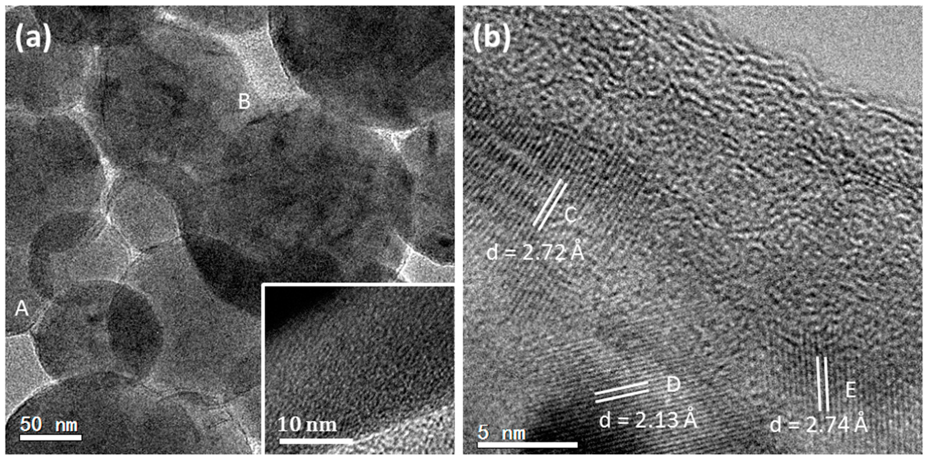
Some even smaller spherical particles were also detected by TEM and their crystallinity was examined by HRTEM. These samples were quite unstable under electron beam irradiation. This is understandable because the crystallites were embedded in an organic matrix. However, if proper specimen treatments and microscopic operation for a low-dose irradiation are performed, HRTEM images of crystal structures of many beam-sensitive samples can still be possible [44]. The TEM image in Figure 8a shows some spherical particles (50 to 200 nm in diameter) found in the M layer in a limpet shell. A closer examination of the particles revealed that most parts of these particles are amorphous (see the inset of Figure 8a), which could be a mixture of ACC and biological components. However, many randomly-orientated nanocrystallites in the amorphous matrix are also detected in some other regions. Figure 8b shows lattice fringes of some nanocrystallites. Two kinds of d-spacings of these nanocrystallites, 2.133 Å and 2.733 Å, were measured and can be indexed to the (004) and (102) planes of vaterite. Similar results were reported in biominerals of earthworm’s calciferous gland by Gago-Duport et al. [45], where vaterite nanocrystallites were developed in ACC particles.
The short nanoneedle particles in the surroundings near the cores (see Figure 7d) are monocrystalline with only a very thin amorphous coating. Figure 9 is an HRTEM image of two cross-linked nanoneedles and the corresponding FFT pattern. The measured d-spacings, dA = 3.67 Å and dB = 3.62 Å with an interplane angle of 60°, can be indexed to the (100) and (010) planes of the hexagonal vaterite structure.
3. Discussion
Although a large number of SEM and HRTEM images of the spherulites, growing in limpet shells, have been obtained and analysed, the growth stages of these spherulites cannot be recognized undoubtedly. Drawing an evolution of the spherulites step-by-step as a function of time is difficult. However, a complete series of specimens during spherulite growth via biomimetic synthesis can be easily achieved. These results may help us to understand the time dependant formation of spherulites in a natural environment if the conditions of the latter can be simulated reasonably well.
Vaterite-type CaCO3 spherulites have been biomimetically synthesized using gelatine as a biological substance [37]. The selection of gelatine is because it has an isoelectric point in a range of 4.7 to 5.2 [46], and has similar functions as a base of CaCO3 deposition with the extracellular polymeric substance (EPS) matrix in biofilms commonly found in the environments for biomineralization. In an aqueous synthetic system containing gelatine (type B), Ca(NO3)2·4H2O, and urea, the growth of CaCO3 and morphology evolution underwent several distinguished steps: Step 1, the formation of vaterite nanocrystallites, ~5 nm in diameter, embedded in a disordered gelatine matrix. Step 2, aggregation of the nanocrystallites into large spherical particles. Step 3, dipole field driven self-orientation of the nanocrystallites and the development of nanoneedles on a spherical core in a radial arrangement, forming spherulites. Step 4, development of a double-layer disk, i.e., two CaCO3 plates sandwiching a gelatine layer. This disk supplies a relatively strong and mirror symmetric dipole field, guiding the orientations of all the nanocrystallites, leading to formations of an equatorial notch and “twin-cauliflower”-shaped particles [37]. It is obvious that, with the increase of growth time, the particle size and ordering of the nanocrystallites increase.
Many structural features observed from the spherulites in the limpet shells are similar with those in the synthetic spherulites [37], particularly the formation of the double-layer disks. We, therefore, assume that the principles of the formation of these spherulites in both biomineralization and biomimetic synthesis are similar. Dipole field interaction between the crystals is believed to be the most important factor governing the formation of the spherulites.
It has been known that hexagonal vaterite has a permanent dipole moment along the c-axis. The (001) surface is terminated with a Ca2+ layer and is positively charged, while the (00) surface is negatively charged with the top surface layer only containing CO32− anions. If the distance between two isoelectric terminals is d, the dipole moment p can be calculated in Debye units:
where qi is the charging magnitude and di is the distance of which the ith anion/cation held. Forces in a dipole field have correlation with distances and the charging level. For a dipole field, if a small particle is located at r+ and r− from positive and negative charges of the dipole, the electric potential V(r) is:
where π is a constant, and is the vacuum permittivity.
If this particle is far enough from the dipole, i.e., r2 ≈ r+r− (r is the distance from the particle to the midpoint of a dipole. θ is the angle between the dipole and the direction from the midpoint of the dipole to the particle), the potential can be written as:
In the dipole field, we have:
where E(r) is the intensity of the dipole field at position r [47]. It can be seen from this equation that the field strength increases remarkably when r decreases, especially to the nanometer scale.
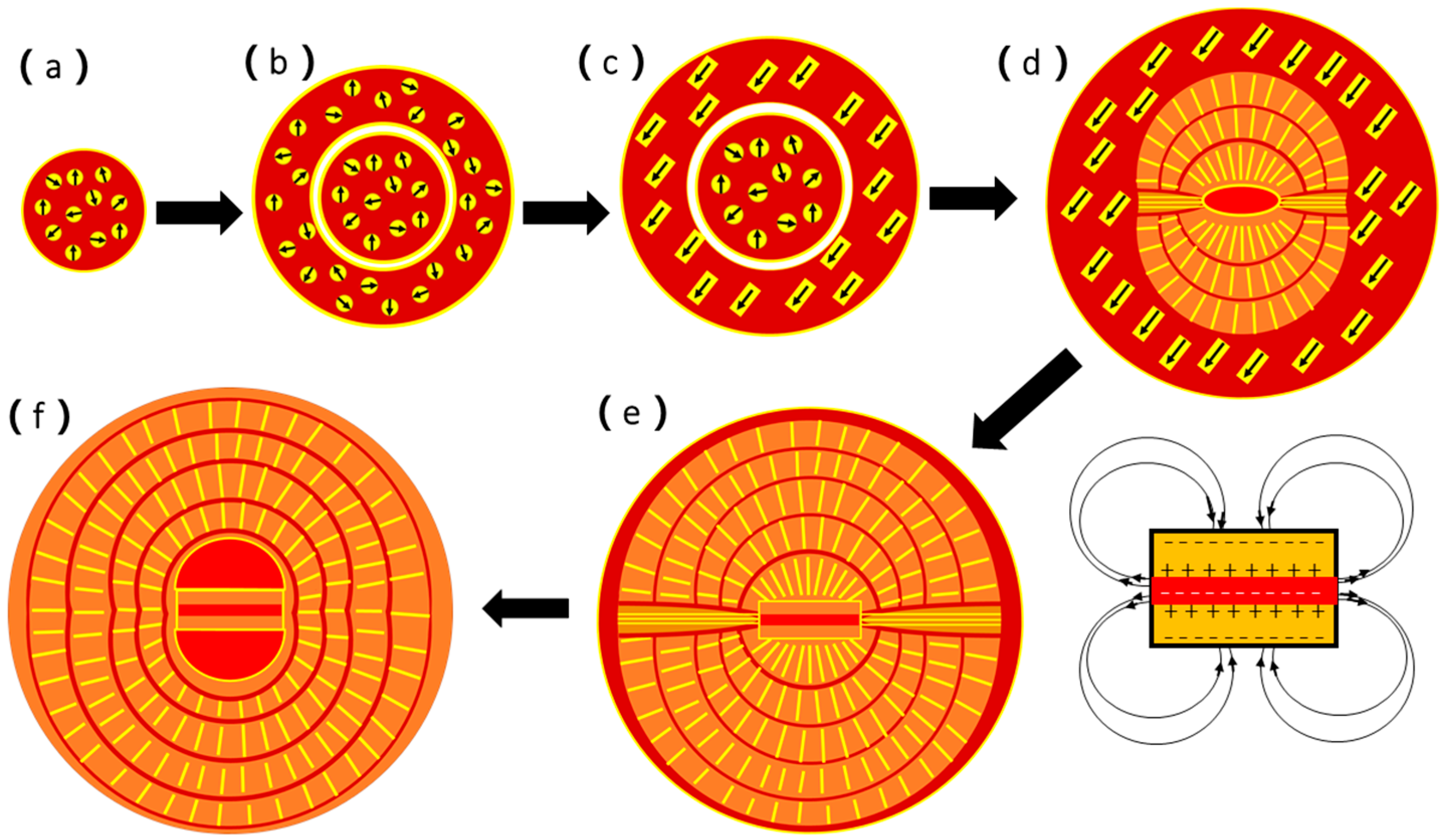
Based on the above discussion, we can now propose a multi-step formation mechanism for the naturally-occurring spherulites as presented in Figure 10.
Step 1: The biofilms with extracellular polymeric substance (EPS) in a gap of the M layer in the limpet shell are normally negatively charged and have a power to attract Ca2+ cations first, followed by attracting CO32− anions, forming an inorganic/organic composite. When the concentration of the inorganic component is high, some spherical particles (50 to 200 nm in diameter) form, separating from the biofilms. Vaterite nanocrystallites develop from amorphous calcium carbonate (ACC) inside these spheres (Figure 10a). A typical experimental image of these spherical particles is shown in Figure 8.
Step 2: When the spheres increase their size and vaterite nanocrystallites grow further, an increase of the density of the central area is faster than the surroundings, and a core particle is separated from the surroundings (Figure 10b), as seen in Figure 7a.
Step 3: The vaterite nanocrystallites grow into short nanoneedles. A dipole field is created from each nanoneedle when it forms a regular shape. An interaction between these nanoneedles force them to self-orientate into a parallel arrangement inside the spherical particles (Figure 10c). The corresponding SEM image is shown in Figure 7d.
Step 4: The core spherical particle undergoes surface re-crystallization into a double-layer disk sandwiching a biological sheet. The formation of such a double-layer disk via an inorganic/organic phase separation was observed in the biomimetic synthesis of CaCO3 in the presence of gelatin [37], and in mirror symmetric growth of ZnO nanoneedles/plates [48,49]. It is also regarded as a good example of two-dimensional reversed crystal growth, a non-classical crystal growth route demonstrating a crystal growth direction from a particle surface to its core [50,51,52]. More importantly, the central biological sheet is normally negatively charged. Therefore, the inner surfaces of both vaterite layers are positively charged and the outer surfaces must be negatively charged. Such a structure offers a strong dipole field, which will guide all the nanocrystallites to adjust their orientations along the field force lines (Figure 10d). The corresponding experimental observation is shown in Figure 2d.
Step 5: When all the nanocrystallites line up into nanoneedles and, later, mesorods, and all these 1D particles lie along the dipole field force lines created from the central double-layer disk, a spherulite forms with two hemispheres separated by a notch where the field strength is the weakest (Figure 10e), as seen in SEM images of Figure 2a,c. Both the spaces between the mesorods and between the hemispherical layers are filled by biological substances. During the above-mentioned process, a phase transformation from vaterite to aragonite takes place. However, the calcite phase was not detected from spherulites, which is the main crystalline phase in other parts of the limpet shells. Another interesting phenomenon is that, although the particles are divided into two hemispheres connected only by a central core, the number of the mesorod layers developed in both hemispheres are the same and the thicknesses of any face-to-face corresponding mesorod layers are uniform (Figure 5a). The growth is, therefore, mirror symmetric.
Step 6: Finally, as depicted in Figure 10f, the density of the spherulites increases. The corresponding mesorod layers in the two hemispheres join together across the notch, which is not visible on the outer surface (Figure 5b). All the mesorod layers in the hemispheres can match the opposite ones and perfectly connect each other. On the other hand, on the both sides of the core disk, further phase separation leads to two hemispherical spaces filled by biological substances, as shown by two dark areas in the core in Figure 5a,b, as well as Figure 6.
Nevertheless, the mechanism presented in Figure 10 is still an assumption, rather than being established unambiguously. Future research is needed to prove all the steps in this mechanism.
4. Experimental
4.1. Specimen Collection and Preparation
Limpets were collected at East Sands, St. Andrews, Scotland. They were sacrificed and the shells were obtained. The limpet shells were embedded in epoxy resin and were easily cut with a low-speed wheel diamond saw. The samples were then polished with sandpaper (1200 grit). A weak acidic solution (5 mmol/L EDTA, pH = 4.0, etching time 30 min) was used for the pre-treatment of the sample, in order to remove the contaminants and fragments on the surface of the sample. The samples were washed with distilled water and acetone. Ultrasonic cleaning was also performed for 30 min.
4.2. Characterization
The SEM images of the polished specimen surfaces were taken on a JSM-5600 scanning electron microscope and a JSM-6700F field-emission gun microscope with an accelerating voltage of 5 kV. Samples were coated with a thin gold film by using a sputter coater to improve the conducting property to avoid electron beam charging. Energy dispersive X-ray (EDX) spectroscopy elemental mapping was performed on an Oxford INCA system (Oxford Instruments, Abingdon, UK) equipped on the JSM-5600.
Powder X-ray diffraction (XRD) patterns were collected on a PANalytical Empyrean diffractometer (PANalytical, Levi, Finland) using copper Kα radiation with λ = 1.5418 Å. The results of PXRD were processed by using Highscore Plus software (PANalytical, Levi, Finland).
For TEM and HRTEM investigations, samples were prepared in either powder or thin plates. The latter was made by using a focused ion beam facility on a FEI Scios dual-beam microscope. TEM and HRTEM images were taken on a JEOL JEM-2011 electron microscope (Jeol, Tokyo, Japan), operated at 200 kV with a Gatan 794 CCD camera.
5. Conclusions
In the present work, the hierarchical microstructures of spherulites grown in limpet shells have been investigated by using SEM and HRTEM. In particular, spherulites at different growth stages were examined. From the results, a formation mechanism of the spherulites has been proposed. It has been assumed that a mirror symmetric dipole field associated with the double-layer disks in the cores is the driving force guiding the self-orientation of the nanocrystallites and, therefore, the morphology evolution. To achieve this, the nanocrystallites embedded in a biological substance matrix must be able to rotate and shift locally. This work may shed light on the research of biomineralization in many other biological systems and biomimetic synthesis of many other crystals.
Supplementary Materials
The following are available online at www.mdpi.com/2073-4352/7/10/319/s1, Figure S1: SAED pattern recorded from a large area in a mesorod, covering polycrystalline area containing self-orientated nanocrystallites and single crystalline region. The corresponding HRTEM images are shown in Figure 4b,c in the paper.
Acknowledgments
The authors would like to thank EPSRC for financial support for the FEG-SEM equipment (EP/F019580/1) and FEI Scios dual-beam microscope (EP/L017008/01).
Author Contributions
Shitao Wu and Chang-Yang Chiang performed most experiments. Wuzong Zhou designed the project and suggested experiments. All the authors contributed to the analysis of the results. Shitao Wu and Wuzong Zhou wrote the paper.
Conflicts of Interest
The authors declare no conflict of interest.
References
- Lin, A.Y.; Meyers, M.A. Growth and structure in abalone shell. Mater. Sci. Eng. A-Struct. 2005, 390, 27–41. [Google Scholar] [CrossRef]
- Lin, A.Y.; Chen, P.Y.; Meyers, M.A. The growth of nacre in the abalone shell. Acta Biomater. 2008, 4, 131–138. [Google Scholar] [CrossRef] [PubMed]
- Sun, J.; Bhushan, B. Hierarchical structure and mechanical properties of nacre: A review. RSC Adv. 2012, 2, 7617–7632. [Google Scholar] [CrossRef]
- Gibbs, S.J.; Poulton, A.J.; Bown, P.R.; Daniels, C.J.; Hopkins, J.; Young, J.R.; Jones, H.L.; Thiemann, G.J.; O’Dea, S.A.; Newsam, C. Species-specific growth response of coccolithophores to palaeocene-eocene environmental change. Nat. Geosci. 2013, 6, 218–222. [Google Scholar] [CrossRef]
- Politi, L.; Talmon, A.; Klein, E.; Weiner, S.; Addadi, L. Sea urchin spine calcite forms via a transient amorphous calcium carbonate phase. Science 2004, 306, 1161–1164. [Google Scholar] [CrossRef] [PubMed]
- Kawano, J.; Shimobayashi, N.; Miyake, A.; Kitamura, M. Precipitation diagram of calcium carbonate polymorphs: Its construction and significance. J. Phys. Condens. Matter 2009, 21, 425102. [Google Scholar] [CrossRef] [PubMed]
- Spanos, N.; Koutsoukos, P.G. The transformation of vaterite to calcite: Effect of the conditions of the solutions in contact with the mineral phase. J. Cryst. Growth 1998, 191, 783–790. [Google Scholar] [CrossRef]
- Berner, R.A. The role of magnesium in the crystal growth of calcite and aragonite from sea water. Geochim. Cosmochim. Acta 1975, 39, 489–504. [Google Scholar] [CrossRef]
- Nassif, N.; Gehrke, N.; Pinna, N.; Shirshova, N.; Tauer, K.; Antonietti, M.; Colfen, H. Synthesis of stable aragonite superstructures by a biomimetic crystallization pathway. Angew. Chem. Int. Ed. Engl. 2005, 44, 6004–6009. [Google Scholar] [CrossRef] [PubMed]
- Rousseau, M.; Lopez, E.; Stempfle, P.; Brendle, M.; Franke, L.; Guette, A.; Naslain, R.; Bourrat, X. Multiscale structure of sheet nacre. Biomaterials 2005, 26, 6254–6262. [Google Scholar] [CrossRef] [PubMed] [Green Version]
- Addadi, L.; Joester, D.; Nudelman, F.; Weiner, S. Mollusk shell formation: A source of new concepts for understanding biomineralization processes. Chem-Eur. J. 2006, 12, 980–987. [Google Scholar] [CrossRef] [PubMed]
- Nudelman, F.; Gotliv, B.A.; Addadi, L.; Weiner, S. Mollusk shell formation: Mapping the distribution of organic matrix components underlying a single aragonitic tablet in nacre. J. Struct. Biol. 2006, 153, 176–187. [Google Scholar] [CrossRef] [PubMed]
- Niederberger, M.; Colfen, H. Oriented attachment and mesocrystals: Non-classical crystallization mechanisms based on nanoparticle assembly. Phys. Chem. Chem. Phys. 2006, 8, 3271–3287. [Google Scholar] [CrossRef] [PubMed]
- Suzuki, M.; Kameda, J.; Sasaki, T.; Saruwatari, K.; Nagasawa, H.; Kogure, T. Characterization of the multilayered shell of a limpet, lottia kogamogai (mollusca: Patellogastropoda), using SEM-EBSD and FIB-TEM techniques. J. Struct. Biol. 2010, 171, 223–230. [Google Scholar] [CrossRef] [PubMed]
- Soldati, A.L.; Jacob, D.E.; Wehrmeister, U.; Hofmeister, W. Structural characterization and chemical composition of aragonite and vaterite in freshwater cultured pearls. Mineral. Mag. 2008, 72, 579–592. [Google Scholar] [CrossRef]
- Wehrmeister, U.; Jacob, D.E.; Soldati, A.L.; Häger, T.; Hofmeister, W. Vaterite in freshwater cultured pearls from China and Japan. J. Gemm. 2007, 31, 269–276. [Google Scholar] [CrossRef]
- Mann, S. Biomineralization: Principles and Concepts in Bioinorganic Materials Chemistry; Oxford University Press: New York, NY, USA, 2001. [Google Scholar]
- Wray, J.; Daniels, F. Precipitation of calcite and aragonite. J. Am. Chem. Soc. 1957, 79, 2031–2034. [Google Scholar] [CrossRef]
- Ogino, T.; Suzuki, T.; Sawada, K. The formation and transformation mechanism of calcium carbonate in water. Geochim. Cosmochim. Acta 1987, 51, 2757–2767. [Google Scholar] [CrossRef]
- Di Lorenzo, M.L. Spherulite growth rates in binary polymer blends. Prog. Polym. Sci. 2003, 28, 663–689. [Google Scholar] [CrossRef]
- Miao, B.; Wood, D.O.N.; Bian, W.; Fang, K.; Fan, M.H. Structure and growth of platelets in graphite spherulites in cast iron. J. Mater. Sci. 1994, 29, 255–261. [Google Scholar] [CrossRef]
- Magill, J.H.; Plazek, D.J. Physical properties of aromatic hydrocarbons. II. Solidification behavior of 1,3,5-tri-α-naphthylbenzene. J. Chem. Phys. 1967, 46, 3757–3769. [Google Scholar] [CrossRef]
- Morse, H.W.; Donnay, J.D.H. Optics and structure of three-dimensional spherulites. Am. Mineral. 1936, 21, 391–426. [Google Scholar]
- Gardner, J.E.; Befus, K.S.; Watkins, J.; Hesse, M.; Miller, N. Compositional gradients surrounding spherulites in obsidian and their relationship to spherulite growth and lava cooling. Bull. Volcanol. 2012, 74, 1865–1879. [Google Scholar] [CrossRef]
- Wright, V.P. Lacustrine carbonates in rift settings: The interaction of volcanic and microbial processes on carbonate deposition. J. Geol. Soc. Lond. Spec. Pub. 2012, 370, 39–47. [Google Scholar] [CrossRef]
- Zelenkova, M.; Sohnel, O.; Grases, F. Ultrafine structure of the hydroxyapatite amorphous phase in noninfectious phosphate renal calculi. Urology 2012, 79, 961–966. [Google Scholar] [CrossRef] [PubMed]
- Granasy, L.; Pusztai, T.; Tegze, G.; Warren, J.A.; Douglas, J.F. Growth and form of spherulites. Phys. Rev. E 2005, 72, 011605. [Google Scholar] [CrossRef] [PubMed]
- Banfield, J.F.; Welch, S.A.; Zhang, H.; Ebert, T.T.; Penn, R.L. Aggregation-based crystal growth and microstructure development in natural iron oxyhydroxide biomineralization products. Science 2000, 289, 751–754. [Google Scholar] [CrossRef] [PubMed]
- Tracy, S.L.; François, C.J.P.; Jennings, H.M. The growth of calcite spherulites from solution: I. Experimental design techniques. J. Cryst. Growth 1998, 193, 374–381. [Google Scholar] [CrossRef]
- Tracy, S.L.; Williams, D.A.; Jennings, H.M. The growth of calcite spherulites from solution II. Kinetics of formation. J. Cryst. Growth 1998, 193, 382–388. [Google Scholar] [CrossRef]
- Rodriguez-Blanco, J.D.; Sand, K.K.; Benning, L.G. ACC and vaterite as intermediates in the solution-based crystallization of CaCO3. In New Perspectives on Mineral Nucleation and Growth; Van Driessche, A.E.S., Kellermeier, M., Benning, L.G., Gebauer, D., Eds.; Springer: Cham, Switzerland, 2017; pp. 93–111. [Google Scholar]
- Addadi, L.; Raz, S.; Weiner, S. Taking advantage of disorder: Amorphous calcium carbonate and its roles in biomineralization. Adv. Mater. 2003, 15, 959–970. [Google Scholar] [CrossRef]
- Tobler, D.J.; Rodriguez-Blanco, J.D.; Sørensen, H.O.; Stipp, S.L.S.; Dideriksen, K. Effect of pH on amorphous calcium carbonate structure and transformation. Cryst. Growth Des. 2016, 16, 4500–4508. [Google Scholar] [CrossRef]
- Bots, P.; Rodriguez-Blanco, J.D.; Benning, L.G.; Shaw, S. Mechanistic insights into the crystallization of amorphous calcium carbonate to vaterite. Cryst. Growth Des. 2012, 12, 3806–3814. [Google Scholar] [CrossRef]
- Mercedes-Martín, R.; Rogerson, M.R.; Brasier, A.T.; Vonhof, H.B.; Prior, T.J.; Fellows, S.M.; Reijmer, J.J.G.; Billing, I.; Pedley, H.M. Growing spherulitic calcite grains in saline, hyperalkaline lakes: Experimental evaluation of the effects of Mg-clays and organic acids. Sediment. Geol. 2016, 335, 93–102. [Google Scholar] [CrossRef]
- Rodriguez-Navarro, C.; Jimenez-Lopez, C.; Rodriguez-Navarro, A.; Gonzalez-Muñoz, M.T.; Rodriguez-Gallego, M. Bacterially mediated mineralization of vaterite. Geochim. Cosmochim. Acta 2007, 71, 1197–1213. [Google Scholar] [CrossRef]
- Greer, H.F.; Liu, M.H.; Mou, C.Y.; Zhou, W.Z. Dipole field driven morphology evolution in biomimetic vaterite. CrystEngComm 2016, 18, 1585–1599. [Google Scholar] [CrossRef]
- Andreassen, J.P.; Flaten, E.M.; Beck, R.; Lewis, A.E. Investigations of spherulitic growth in industrial crystallization. Chem. Eng. Res. Des. 2010, 88, 1163–1168. [Google Scholar] [CrossRef]
- Andreassen, J.P. Formation mechanism and morphology in precipitation of vaterite—nano-aggregation or crystal growth? J. Cryst. Growth 2005, 274, 256–264. [Google Scholar] [CrossRef]
- Zhong, C.; Chu, C.C. On the origin of amorphous cores in biomimetic CaCO3 spherulites: New insights into spherulitic crystallization. Cryst. Growth Des. 2010, 10, 5043–5049. [Google Scholar] [CrossRef]
- Zhou, G.T.; Yao, Q.Z.; Ni, J.; Jin, G. Formation of aragonite mesocrystals and implication for biomineralization. Am. Mineral. 2009, 94, 293–302. [Google Scholar] [CrossRef]
- Nan, Z.; Shi, Z.; Yan, B.; Guo, R.; Hou, W. A novel morphology of aragonite and an abnormal polymorph transformation from calcite to aragonite with PAM and CTAB as additives. J. Colloid. Interface. Sci. 2008, 317, 77–82. [Google Scholar] [CrossRef] [PubMed]
- Kamhi, S.R. On the structure of vaterite CaCO3. Acta Crystallogr. 1963, 16, 770–772. [Google Scholar] [CrossRef]
- Greer, H.F.; Zhou, W.Z. Electron diffraction and HRTEM imaging of beam sensitive materials. Crystallogr. Rev. 2011, 17, 163–185. [Google Scholar] [CrossRef]
- Gago-Duport, L.; Briones, M.J.; Rodriguez, J.B.; Covelo, B. Amorphous calcium carbonate biomineralization in the earthworm’s calciferous gland: Pathways to the formation of crystalline phases. J. Struct. Biol. 2008, 162, 422–435. [Google Scholar] [CrossRef] [PubMed]
- Bauermann, L.P.; Del Campo, A.; Bill, J.; Aldinger, F. Heterogeneous nucleation of ZnO using gelatin as the organic matrix. Chem. Mater. 2006, 18, 2016–2020. [Google Scholar] [CrossRef]
- Walker, J.D. Fundamentals of Physics Extended; Wiley: New York, NY, USA, 2010. [Google Scholar]
- Liu, M.-H.; Tseng, Y.-H.; Greer, H.F.; Zhou, W.Z.; Mou, C.Y. Dipole field guided orientated attachment of nanocrystals to twin-brush ZnO mesocrystals. Chem. Eur. J. 2012, 18, 16104–16113. [Google Scholar] [CrossRef] [PubMed]
- Greer, H.F.; Zhou, W.Z.; Liu, M.-H.; Tseng, Y.-H.; Mou, C.-Y. The origin of ZnO twin crystals in bio-inspired synthesis. CrystEngComm 2012, 14, 1247–1255. [Google Scholar] [CrossRef]
- Chen, X.Y.; Qiao, M.H.; Xie, S.H.; Fan, K.N.; Zhou, W.Z.; He, H.Y. Self-construction of core-shell and hollow zeolite analcime icositetrahedra: A reversed crystal growth process via oriented aggregation of nanocrystallites and recrystallization from surface to core. J. Am. Chem. Soc. 2007, 129, 13305–13312. [Google Scholar] [CrossRef] [PubMed]
- Zhou, W.Z. Reversed crystal growth: Implications for crystal engineering. Adv. Mater. 2010, 22, 3086–3092. [Google Scholar] [CrossRef] [PubMed]
- Yao, J.F.; Li, D.; Zhang, X.Y.; Kong, C.H.; Yue, W.B.; Zhou, W.Z.; Wang, H.T. Cubes of zeolite A with an amorphous core. Angew. Chem. Int. Ed. 2008, 47, 8397–8399. [Google Scholar] [CrossRef] [PubMed]
Figure 1.
(a) Live limpets on site. (b) SEM image of some spherulites in the myostracum layer. (c) Schematic drawing of a cross-section by cutting from the apex of a limpet shell. The cutting position is indicated by a white line in (a). Six layers are marked. The arrow points to the myostracum layer where the spherulites were found.
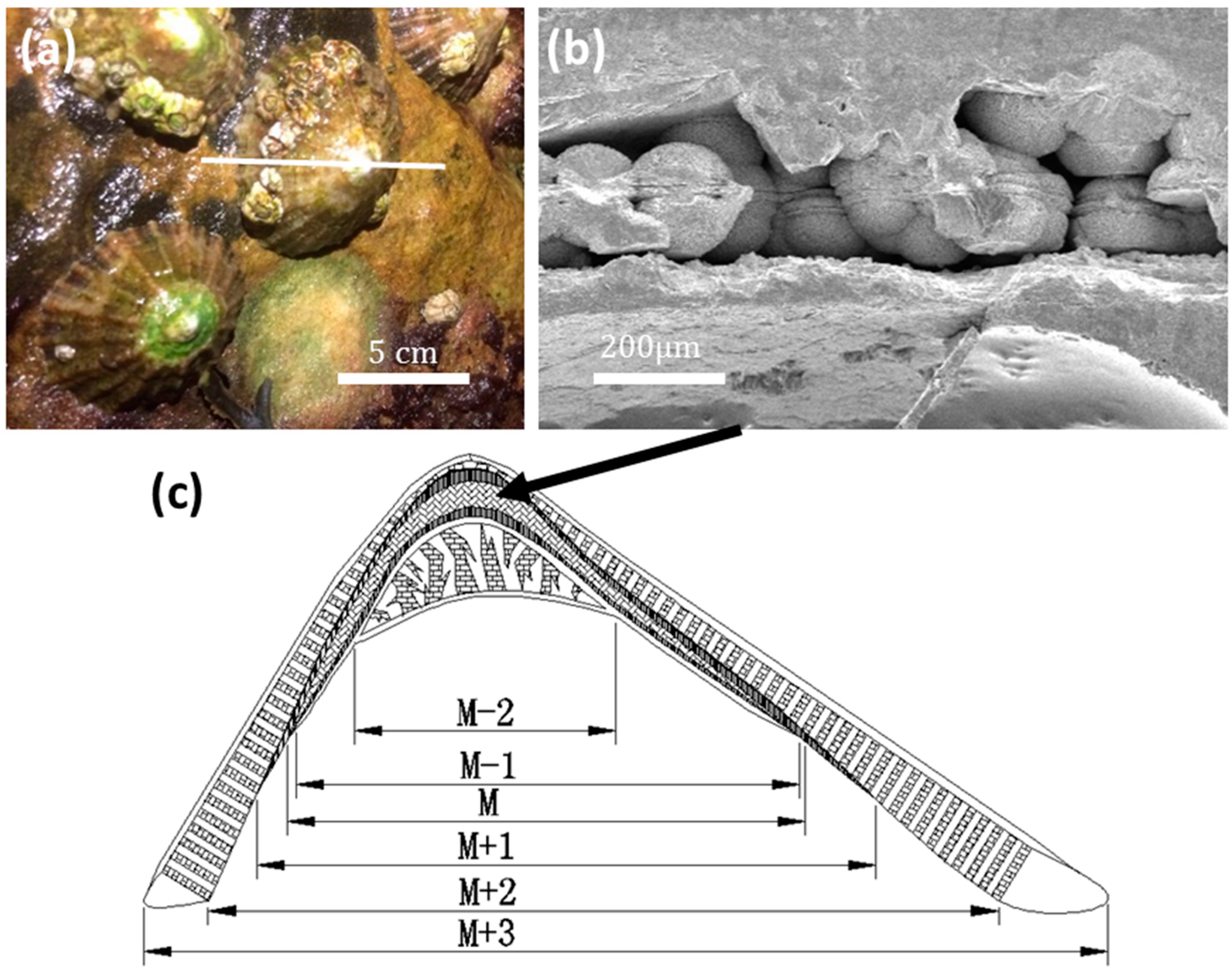
Figure 2.
SEM images of some spherulites at high magnifications. (a) Whole spherulites with a rough surface. (b) Morphology of mesorods in the outer layer of a spherulite. The arrow indicates a skin of a mesorod. (c) Cross-section of a central area of spherulite. The inset is an enlarged image showing the double-layer disk in the centre. The two hemispheres are marked by “A”. (d) Higher magnification image of the sandwich disk (B-A-B) of a spherulite at an early stage. The different layers from the centre are marked from A to D.
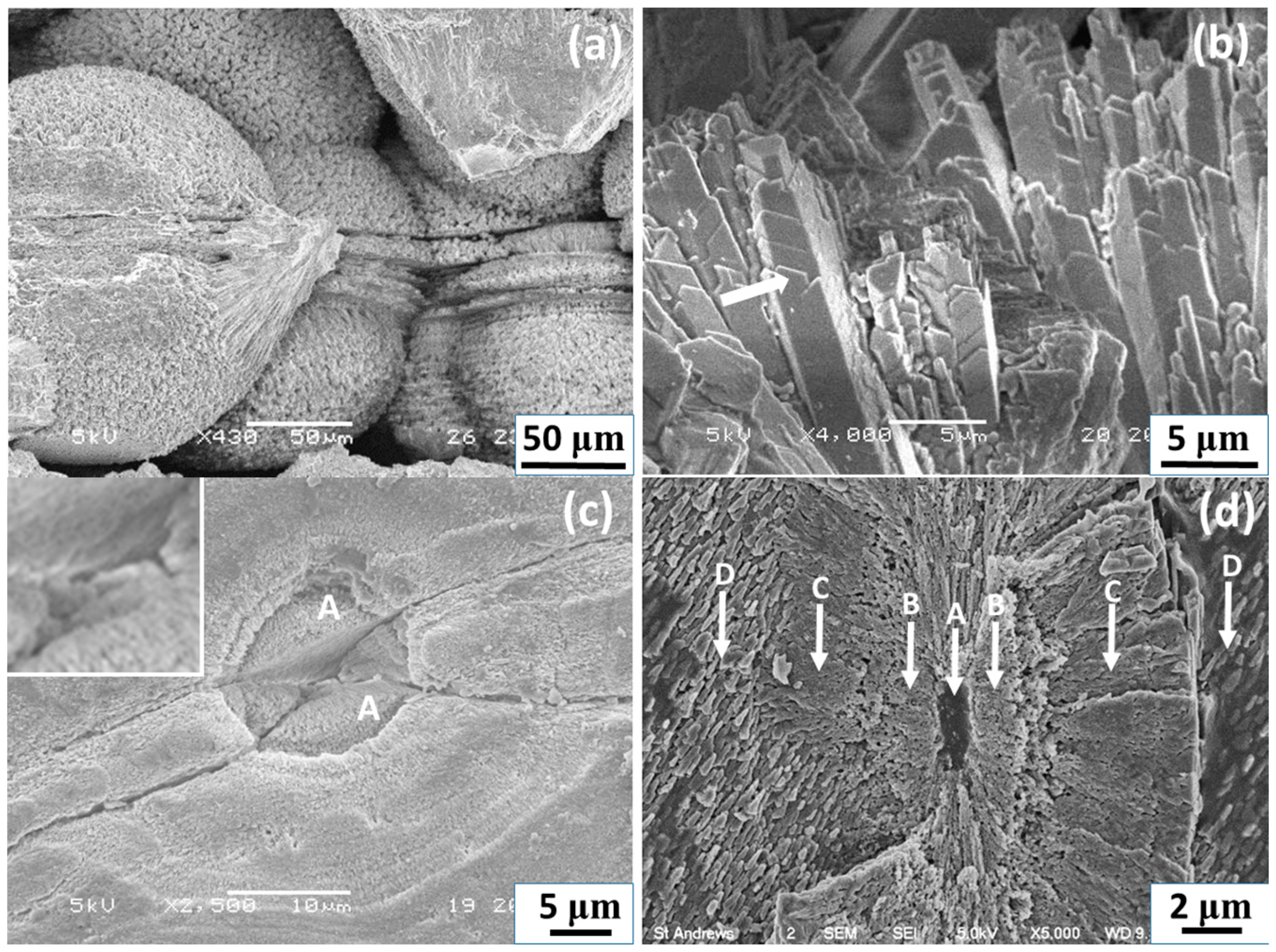
Figure 3.
Powder XRD pattern of a crushed limpet shell, showing the presence of calcite (C), aragonite (A), and vaterite (V) CaCO3.
Figure 3.
Powder XRD pattern of a crushed limpet shell, showing the presence of calcite (C), aragonite (A), and vaterite (V) CaCO3.

Figure 4.
HRTEM images of a mesorod in a spherulite from edge to centre, (a) polycrystalline edge with randomly-orientated nanocrystallites, (b) an area with all nanocrystallites self-orientated and connected, and (c) a single crystalline region. The arrows indicate the long axis of the mesorod. The inset of (a) shows a TEM image of the mesorod and the insets in (b) and (c) are the corresponding FFT patterns. The diffraction spots are indexed to the aragonite structure.

Figure 5.
SEM images of cross-sections of spherulites, showing (a) an entire spherulite with the notch about to disappear, (b) half-spherulite without a notch, (c) porous mesorod layers in a spherulite, and (d) individual mesorods in spherulites.
Figure 5.
SEM images of cross-sections of spherulites, showing (a) an entire spherulite with the notch about to disappear, (b) half-spherulite without a notch, (c) porous mesorod layers in a spherulite, and (d) individual mesorods in spherulites.
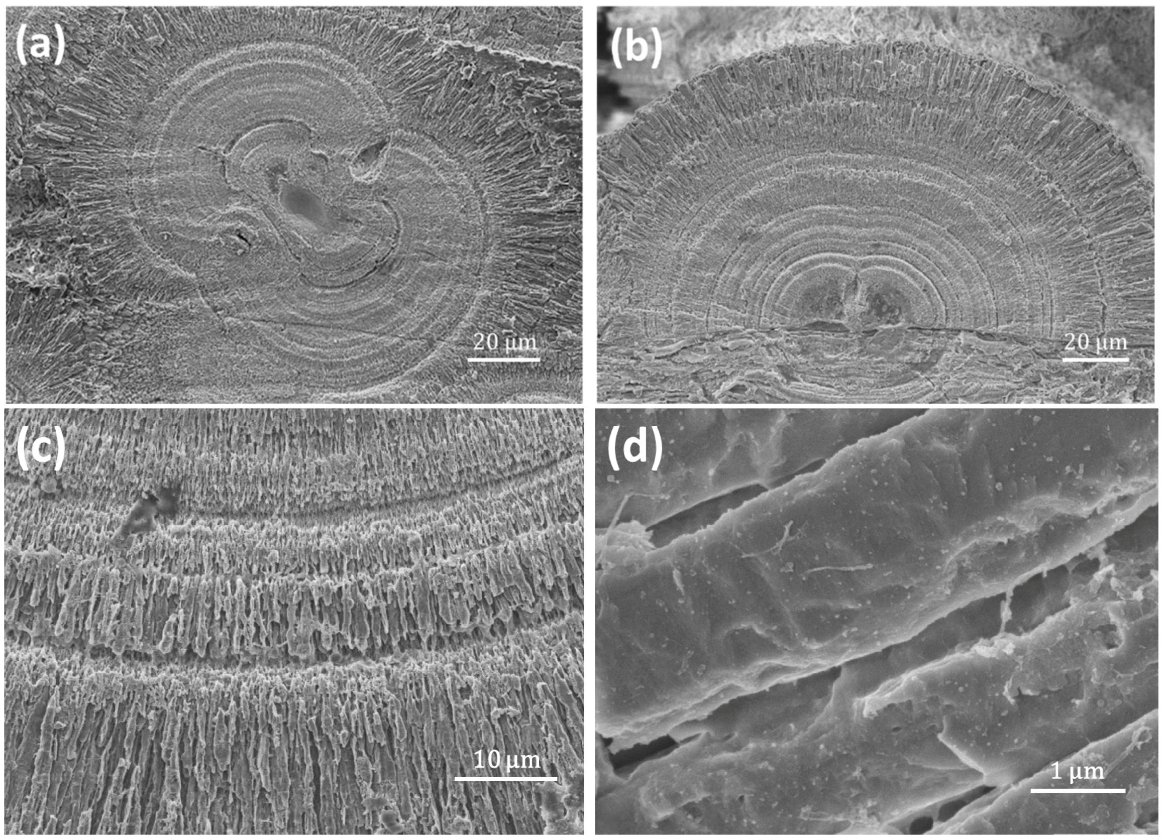
Figure 6.
Cross-section SEM image of a half spherulite, and the corresponding EDX elemental mapping showing distributions of O, Ca, and C.
Figure 6.
Cross-section SEM image of a half spherulite, and the corresponding EDX elemental mapping showing distributions of O, Ca, and C.
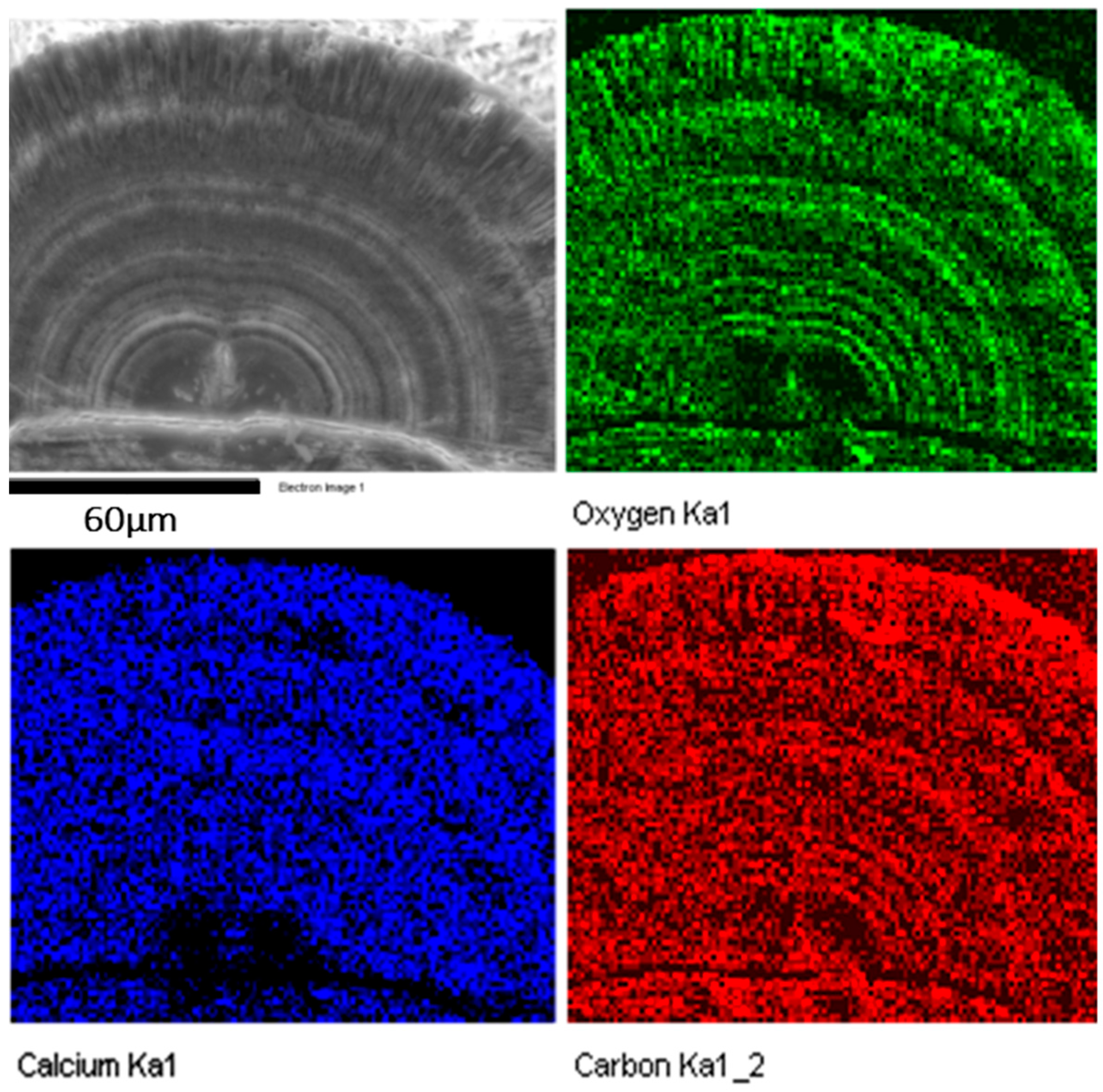
Figure 7.
FEG-SEM images of the sea urchin-like particles in the central areas of some early stage spherulites. (a) Cross-section of the whole particle when nanorods/mesorods have not formed. (b) Another core particle with a low density in the early stage of growth. (c) A larger, high-density spherical core separated from the surroundings. (d) A core particle with many nanocrystallites embedded in biological substances and some short nanoneedle particles, lying along the same orientation, are developed in the surroundings.
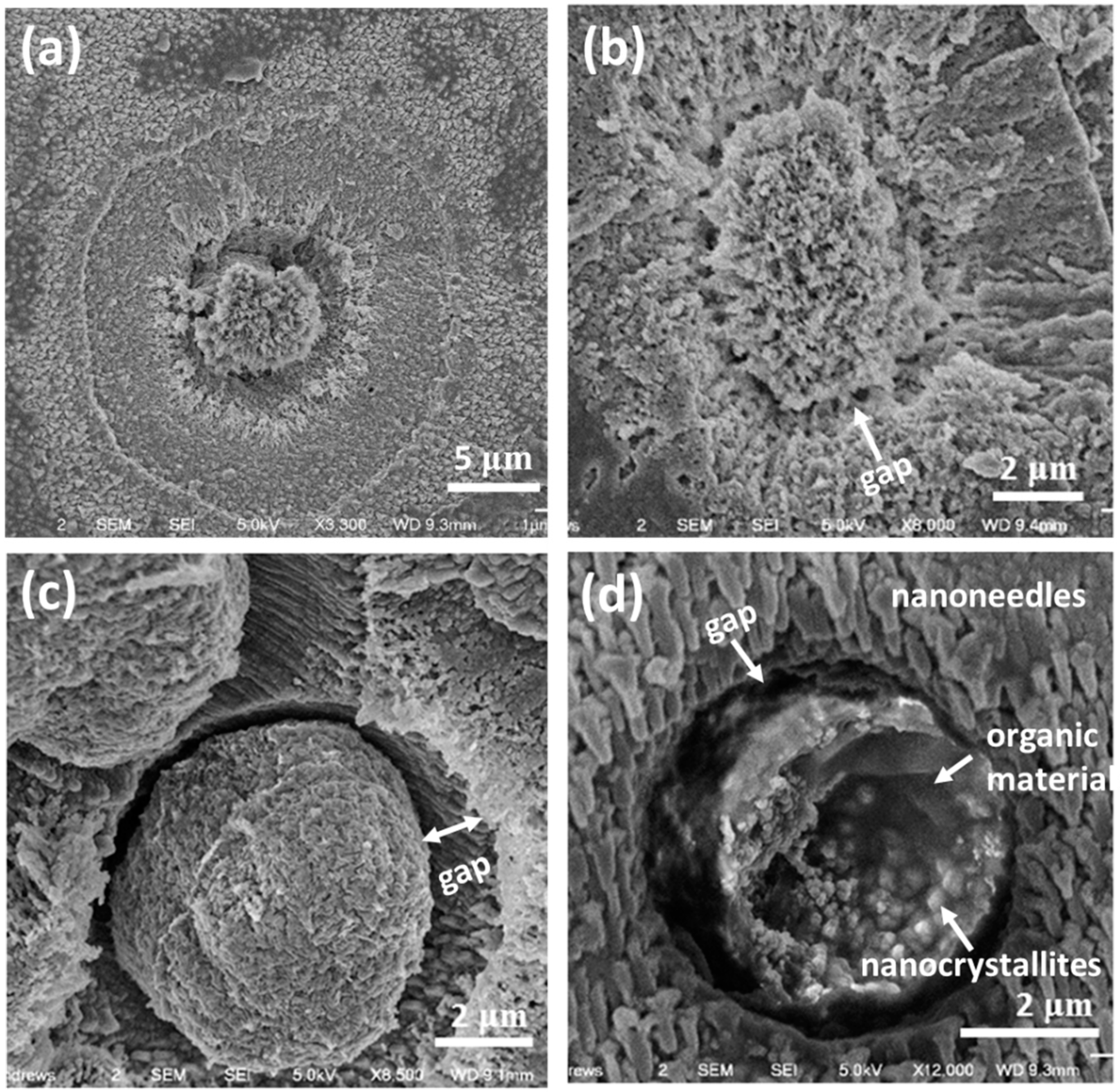
Figure 8.
(a) TEM image of small spherical particles found in the M layer in a limpet shell. The inset is a HRTEM image recorded from area A. (b) A HRTEM image from area B in (a). Some d-spacings are measured from randomly-orientated nanocrystallites and can be indexed to the (C, E) (102) and (D) (004) planes of vaterite.

Figure 9.
(a) HRTEM image of two cross-linked nanoneedles. (b) The corresponding FFT pattern, which is indexed to the hexagonal vaterite structure.
Figure 9.
(a) HRTEM image of two cross-linked nanoneedles. (b) The corresponding FFT pattern, which is indexed to the hexagonal vaterite structure.
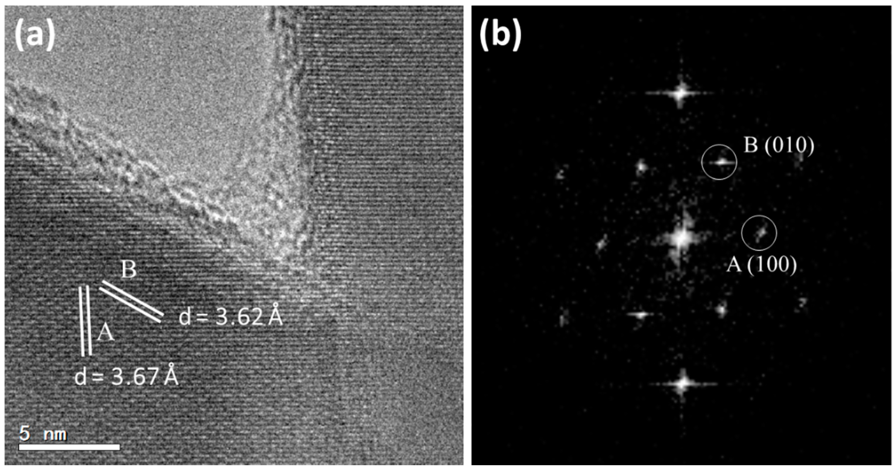
Figure 10.
Schematic drawing of a proposed formation mechanism of spherulites grown in limpet shells. (a) Small spherical particles of inorganic/organic composite, in which vaterite nanocrystallites (yellow) are developed. (b) Separation of the core and the surroundings. (c) Formation of parallel vaterite short nanoneedles. (d) Formation of the central double-layer disk. (e) Formation of spherulites with two hemispheres separated by a notch. (Right bottom) A schematic drawing of the dipole field from the central disk. (f) Final stage of the formation of the spherulites.

© 2017 by the authors. Licensee MDPI, Basel, Switzerland. This article is an open access article distributed under the terms and conditions of the Creative Commons Attribution (CC BY) license (http://creativecommons.org/licenses/by/4.0/).
Share and Cite
MDPI and ACS Style
Wu, S.; Chiang, C.-Y.; Zhou, W. Formation Mechanism of CaCO3 Spherulites in the Myostracum Layer of Limpet Shells. Crystals 2017, 7, 319. https://doi.org/10.3390/cryst7100319
AMA Style
Wu S, Chiang C-Y, Zhou W. Formation Mechanism of CaCO3 Spherulites in the Myostracum Layer of Limpet Shells. Crystals. 2017; 7(10):319. https://doi.org/10.3390/cryst7100319
Chicago/Turabian StyleWu, Shitao, Chang-Yang Chiang, and Wuzong Zhou. 2017. "Formation Mechanism of CaCO3 Spherulites in the Myostracum Layer of Limpet Shells" Crystals 7, no. 10: 319. https://doi.org/10.3390/cryst7100319
Note that from the first issue of 2016, this journal uses article numbers instead of page numbers. See further details here.