
Ultrafast Photoalignment: Recording a Lens in a Nanosecond

1
BEAM Engineering for Advanced Measurements Co., 1300 Lee Rd., Orlando, FL 32810, USA
2
Air Force Research Laboratory, Wright-Patterson Air Force Base, OH 45433, USA
*
Author to whom correspondence should be addressed.
Crystals 2017, 7(11), 338; https://doi.org/10.3390/cryst7110338
Submission received: 9 October 2017
/
Revised: 31 October 2017
/
Accepted: 31 October 2017
/
Published: 3 November 2017
(This article belongs to the Special Issue Micro and Nano Patterned Substrates for Liquid Crystal Alignment)
Abstract
:Liquid crystals can be photoaligned with a single nanosecond pulse acting on thin photoanisotropic coatings on the cell substrates. This phenomenon was demonstrated for pulses of 532 nm and 355 nm wavelengths (second and the third harmonics of a Nd:YAG laser). Direct printing of liquid crystal cycloidal diffractive waveplates and diffractive waveplate lenses characterized by high spatial frequencies required only a mJ energy. The liquid crystal alignment dynamics reveal a fast component related to photoalignment of molecules within the photoanisotropic layer and a slower component related to alignment of the liquid crystal within the cell.
1. Introduction
Diffractive waveplates (the fourth generation of optics) have resulted in a breakthrough in optics and photonic applications by enabling the reproduction of all classic functions of conventional refractive optics instead using thin film coatings [1,2,3]. The micrometer thin films can act as lenses, prisms, spiral phase plates, etc. over a broad wavelength region, comparable to that of a glass lens or prism [4,5]. In addition to this function, these 4G optics also greatly simplify the optics manufacturing technology steps usually needed to fabricate complex, bulky refractive elements. A variety of optical components can now be produced with a single optical recording system, using coating techniques (including inkjet, spin, spray, and even dip coating) instead of complex subtractive techniques like polishing, without the need for high temperature processes, and on the second to minute timescale. This capability is extremely important for large optics where just cooling down of the glass blanks for mirrors can take months. In this paper, a new breakthrough enabled by 4G optics, the fabrication of optical components with a single nanosecond pulse, is explored.
Diffractive waveplates are components utilizing the modulation of the Pancharatnam phase, which is also referred to as “geometrical phase”, since it depends only on the anisotropy axis orientation of a birefringent film with thickness chosen to meet the half-wave retardation condition for the wavelength of interest. Liquid crystals (LCs) and liquid crystal polymers (LCPs) provide an opportunity for the modulation of the optical anisotropy axis over a large area, and with a high spatial frequency. Due to the high optical anisotropy of Δn ~ 0.2 for commercial and Δn ~ 1 reported for research materials, LC diffractive waveplates need only be a micrometer thin to fulfill the half-wave retardation condition for visible and infrared wavelengths [6,7]. Modulation of the LC alignment in the bulk is typically induced by producing anisotropic conditions at the interface of the LC and a substrate. For our purposes, the substrate is coated with a special photoanisotropic material. Azobenzene-based materials provide many advantages compared to polymers, including low exposure energy density, thin layer thickness, high spatial resolution, reversibility, and wide spectral range [8,9].
PAAD-series azobenzene materials (BEAM Co., Orlando, FL, USA) have been successfully used for recording a wide variety of high quality and large area diffractive waveplates with functions of gratings [10,11], lenses [4,5], vortices [12,13], and a large variety of complex spatial light polarization modulators [14]. The spectral range of absorption for these materials extends from the UV to green wavelengths. These PAAD coatings need to be only a nanometer thick to enable efficient photoalignment capability, thereby not affecting the overall color quality of the final optic. When subjected to a CW laser beam, photoalignment requires only a minute of exposure corresponding to approximately 0.5 J/cm2 exposure dose.
In this paper, the energy/energy density levels required for photoalignment with a laser of a single short pulse is explored. Reducing the optical recording time from minutes to nanoseconds is highly important for scaling up production volumes and increasing overall throughput. Another opportunity provided by short pulse recording is recording patterns of high spatial frequencies avoiding the need for stabilizing the system against mechanical and environmental noises. A common Nd:YAG laser operated at its second (532 nm) and third (355 nm) harmonics was used. Planar-to-twist photoinduced transformation of a nematic LC revealed the fast, as well as slow, components in the dynamics relative to the orientation process within the photoalignment layer and within the LC.
2. Experimental Set-Up
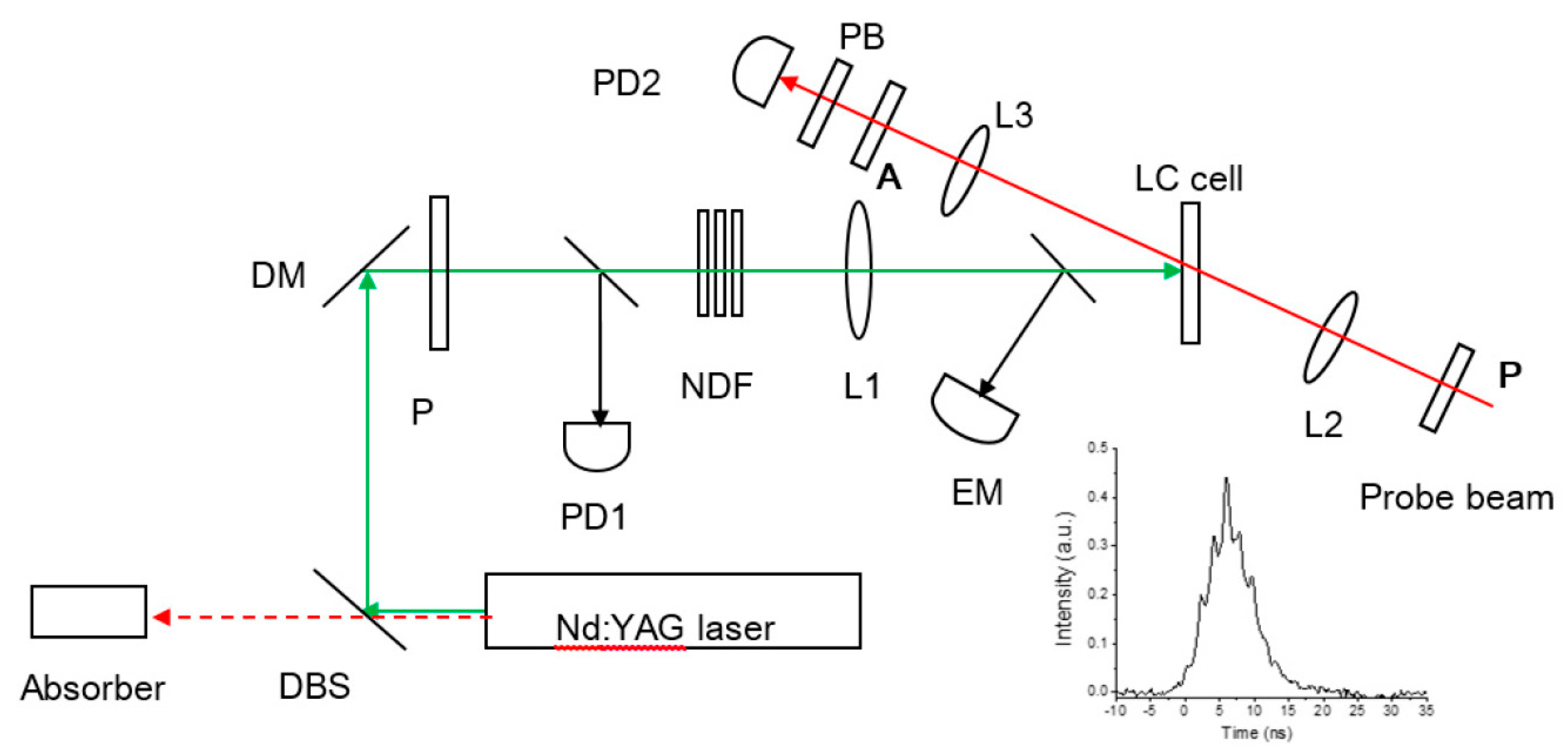
The setup comprised a pump and a probe subsystem as shown in Figure 1. A Nd:YAG laser was used as a source of pump nanosecond pulses, operated at λ = 355 nm or 532 nm. A dichroic mirror and a dichroic filter allowed selection of the desired wavelength, blocking all the infrared (λ = 1064 nm) from reaching the LC cells. The pulse energy at the input of the NLC cell was varied from 2 to 10 mJ with a set of neutral density filters NDF, and was monitored with an energy meter EM. Silicon photodetectors PD1 and PD2 with a rise time <1 ns and a spectral response in 200 nm–1100 nm range characterized the temporal profile of the ns pulses and the probe CW beams. The temporal profile of the pulses were registered with the aid of an oscilloscope with 400 ps/div time resolution. The pulse duration at half maximum Δt1/2 varied from 6.5 ns to 7.5 ns by changing Q-switch delay time and flashlamp discharge voltage. The pump laser beam was slightly focused with lens L1 (400 mm focal length) to explore LC cells with different diameters of the beam (0.8 mm to 2 mm). The pump radiation was linearly polarized parallel to the LC orientation axis n.
The probe setup for characterization of the process dynamics included a red diode laser emitting at 635 nm. The probe beam was focused on the LC cell with a lens L2 of 150 mm focal length and was further collimated with the lens L3 of 80 mm focal length into the photodetector PD2 at the output of the LC cell. The probe beam size, 0.2 mm, was smaller than that of the pump beam. A pump block filter PB in front of the photodetector blocked the scattered radiation at the pump wavelength. The analyzer axis A was parallel to the probe beam polarizer axis P, and was parallel to LC orientation n. This arrangement allowed registration of photoinduced planar-to-twist re-alignment of the LC in the cell.
3. Materials and Characterization
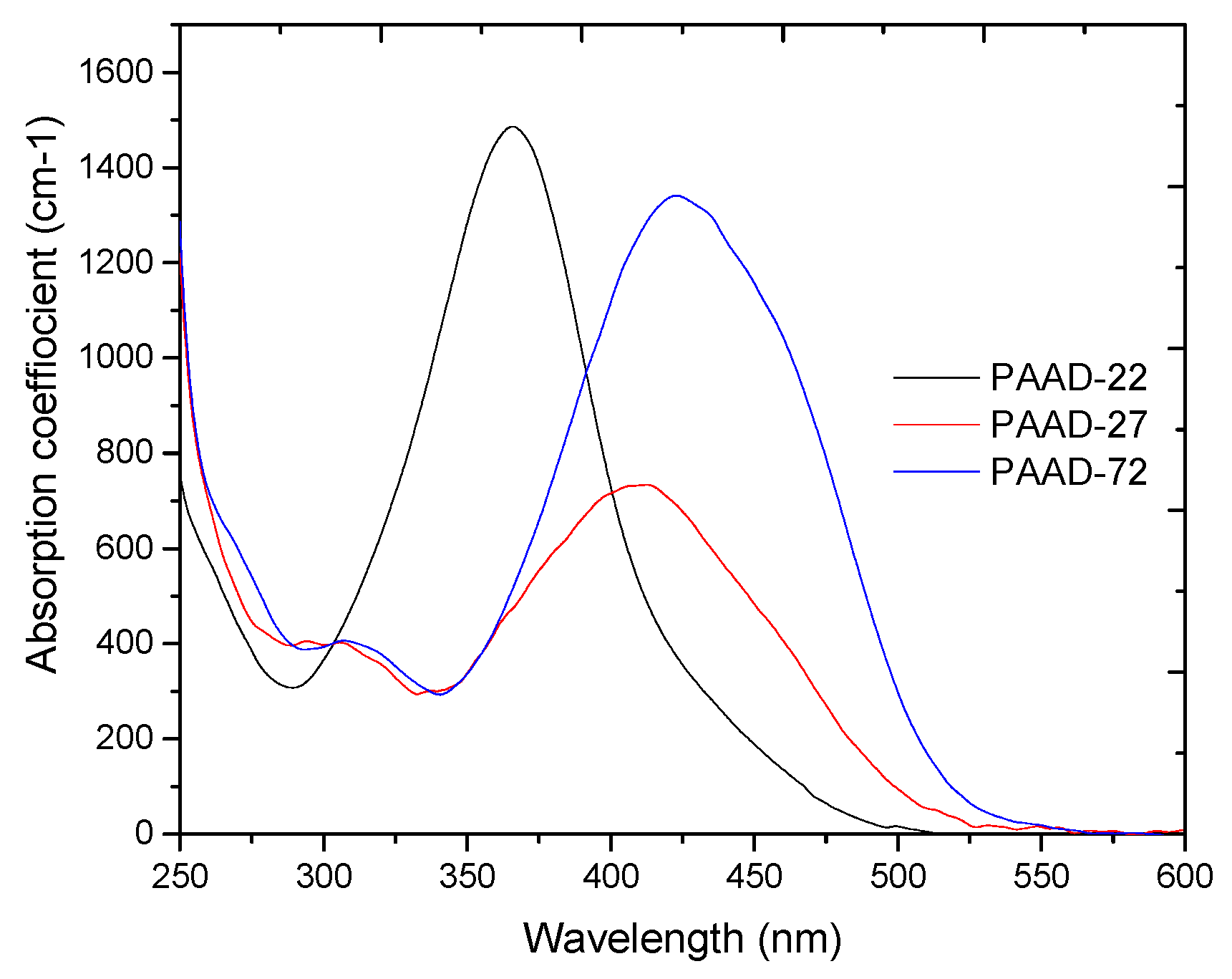
Solutions of photoaligning azo dyes PAAD-22, PAAD-27 and PAAD-72 (BEAM Co., Orlando, FL, USA), 1 wt.% in dimethylformamide (DMF), were used in the tests due to their large absorption for both UV and visible wavelengths, Figure 2.
The photoalignment dynamics were tested in planar aligned nematic LC (6CHBT [15]) cells with one or both substrates coated with a PAAD layer. The PAAD solution was spin-coated on glass substrates at 3000 rpm over 60 s. PAAD coated substrates were next exposed with linear polarized blue LED light (λ = 459 nm, I = 15 mW/cm2) for 15 min creating homogeneous alignment conditions. The substrates for producing rigid planar orientation of LC molecules were obtained by rubbing a polyvinyl alcohol (PVA) coating. The solution of PVA, 0.5 wt.% in distilled water, was spin-coated on glass substrates at the same conditions as the PAAD. LC cells of 6-μm cell gap obtained by spacers as well as LC cells of 1.5–2 μm cell gap obtained by assembling the cells without spacers were studied.
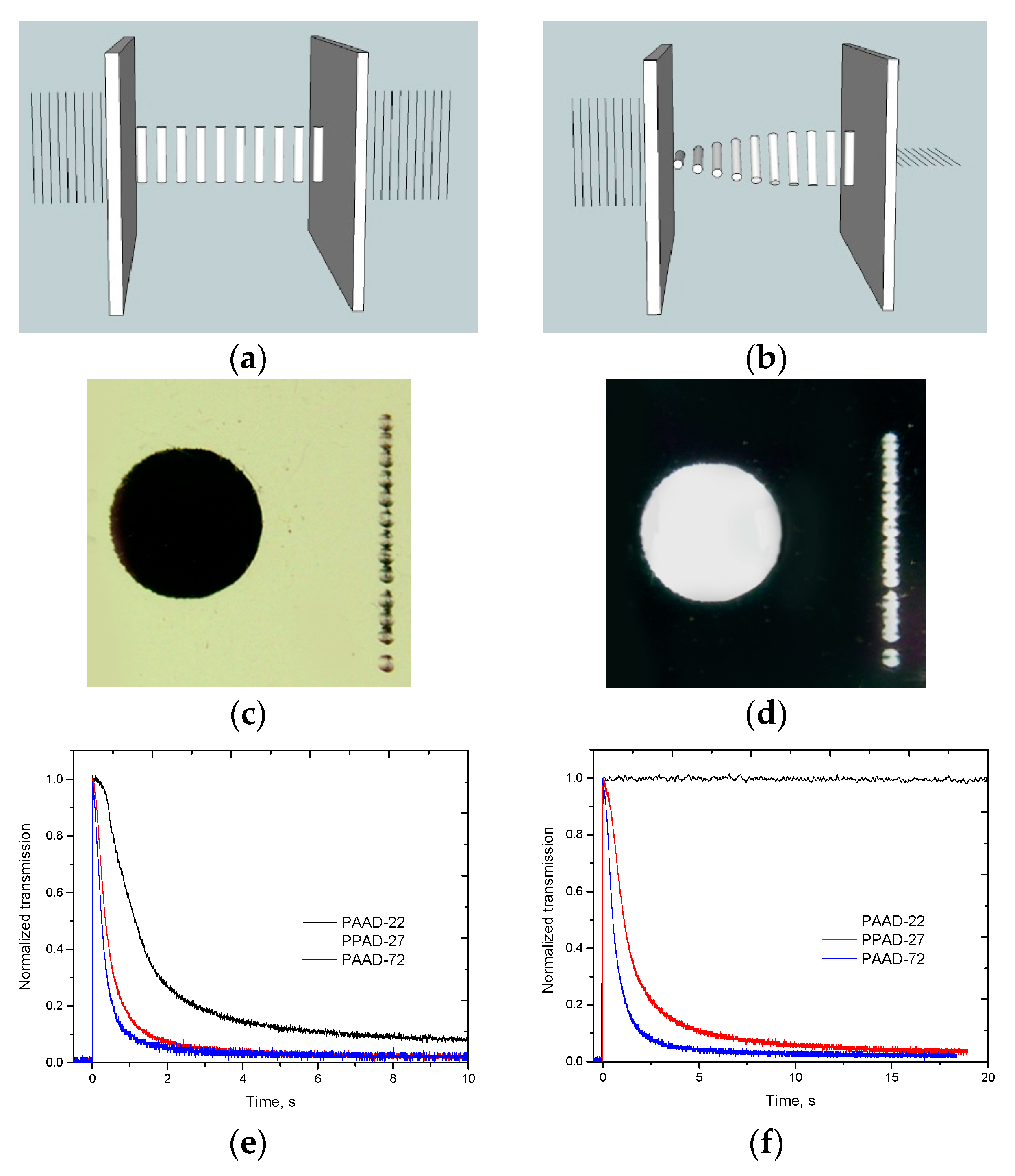
The dynamics of LC photoalignment with a linearly polarized cw beam is shown in Figure 3 for Argon-ion laser beams of 457 nm and 514 nm wavelengths, 0.5 W/cm2 power density and 0.7 mm beam diameter on the LC cell. The LC was planarly oriented in a cell made of PAAD- and PVA-coated substrates (PAAD/PVA cell), with the PAAD side facing the incident laser beam. The cell was between a polarizer and an analyzer that had their axes parallel to the LC orientation, Figure 3a. The transmission of this system decreases when the planar alignment of the LC is converted into 90° twist during the photoalignment, Figure 3b. The transmission of the system for PAAD-27/PVA and PAAD-72/PVA LC cells decreased nearly to zero within a couple of seconds for the 457 nm exposure and approximately 15 s for the 514 nm beam. PAAD-22 was responsive to the λ = 457 nm beam, but not to the green beam (514 nm) as would be expected from its absorption spectra shown in Figure 2.
Planar-twist re-alignment within the LC cells could be induced even with single nanosecond pulses. The Nd:YAG laser beam was slightly focused with a lens of 400 mm focal length into spots of about 1 mm size on the PAAD layer. Photos in Figure 3c,d show series of spots on the right hand side of the images which correspond to photoalignment with a single 6.5 ns pulse of Nd:YAG laser beam of 532 nm wavelength and 0.7 J/cm2 energy density in a pulse. In more detail, Figure 4 shows areas of twist LC alignment created in PAAD-72/PVA and PAAD-27/PVA LC cells with λ = 532 nm pulses and in a PAAD-22/PVA LC cell with λ = 355 nm pulses.
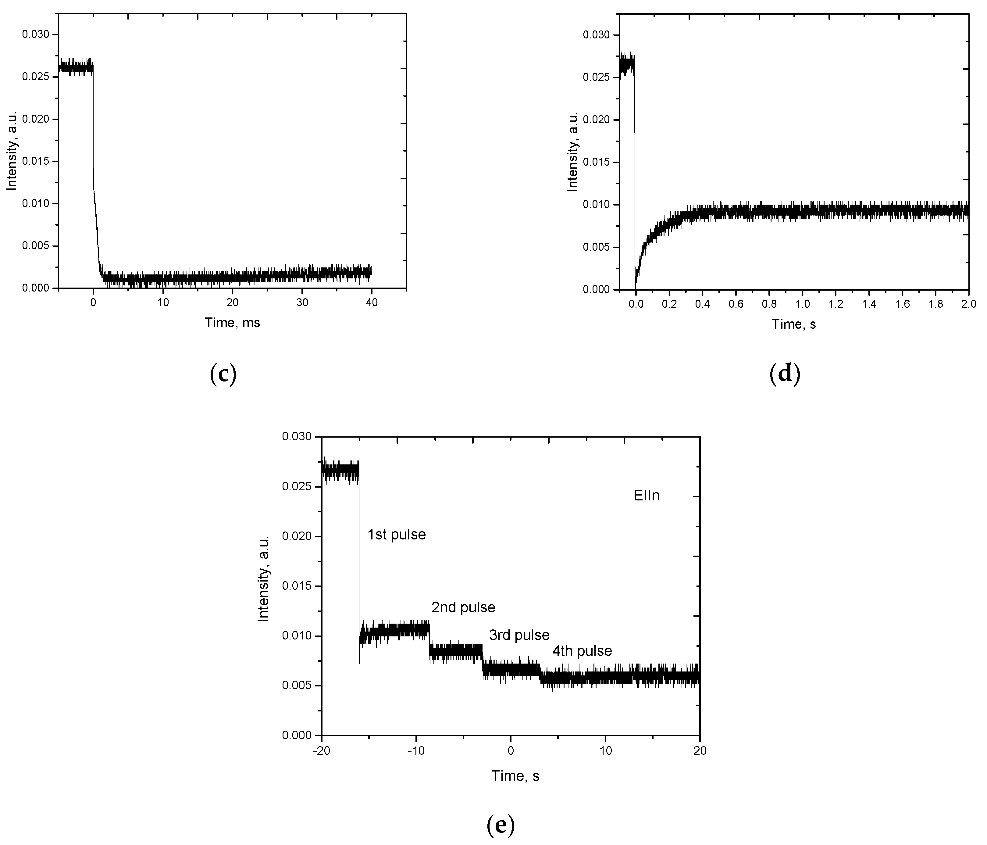
The dynamics of this photoinduced re-alignment from a planar to twist state reveals a fast initial stage, Figure 5a, related to the alignment of PAAD molecules at the surface, and longer processes, Figure 5c,d, continuing well beyond the pulse excitation time related to the reorientation of the LC itself. The oscillations at the 100 ns scale may be related to the interaction of the interface LC molecules with PAAD layer and other processes, like formation of transient domains. Note that the PAAD molecules do not change their orientation gradually from one to another angle. The process, rather, takes place by increased concentration of PAAD molecules in a direction perpendicular to the light polarization. At a certain concentration, the alignment forces along the new direction prevail, leading to re-alignment of LC molecules.
The results in Figure 5 corresponding to PAAD-27/PVA LC cell subject to λ = 532 nm pulse also reveal an interesting feature. The twist state obtained within a millisecond undergoes slow relaxation to an intermediate orientation state characterized by incomplete darkening of the polarizer/analyzer system comprising the LC. Subsequent pulses improve the twist orientation state of LC as seen in Figure 5e.
4. Printing Diffractive Waveplates (DW) in PAAD-27 with 532 nm Pulse
This observation led to the exploration of the possibility of printing complex optical components with a single pulse. The recording was performed using a template liquid crystal polymer diffractive waveplate as a spatial polarization modulator [16]. To transform a linear polarized beam into a beam of spatially modulated polarization state, the template diffractive waveplate was tuned to close to the half-wave retardation condition for 532 nm.
A cycloidal diffractive waveplate (CDW), the simplest diffractive waveplate presenting a linear rotation of the optical anisotropy axis along a single coordinate, with a 5 μm period was utilized. This system produces a light beam with a 2.5 μm period of polarization modulation due to its half-wave plate nature. Printing was performed with spatial polarization modulators in direct contact with the LC cell. The laser beam was capable of photoaligning both substrates of the cell simultaneously, due to the close distance between them and negligibly low absorption by the PAAD layers.
The cycloidal orientation pattern in a LC cell, Figure 6a, is stable if the cell thickness is thinner than roughly half of the modulation period [17]. To fulfil this condition, the LC cell was prepared without spacers using substrates coated with PAAD-27. The obtained cell gap, based on our experience, was approximately 1 μm, due to the nonuniformity of the photoalignment material at the very edges of the substrate. The obtained gap proved thin enough for the purposes of demonstration of a high quality grating with no concern about the diffraction efficiency spectrum. A polarizing microscope photo of the resultant polarization grating obtained with a pulse of 7.2 ns duration and 6.7 mJ energy, corresponding to 0.85 J/cm2 exposure energy density, is shown in Figure 6.
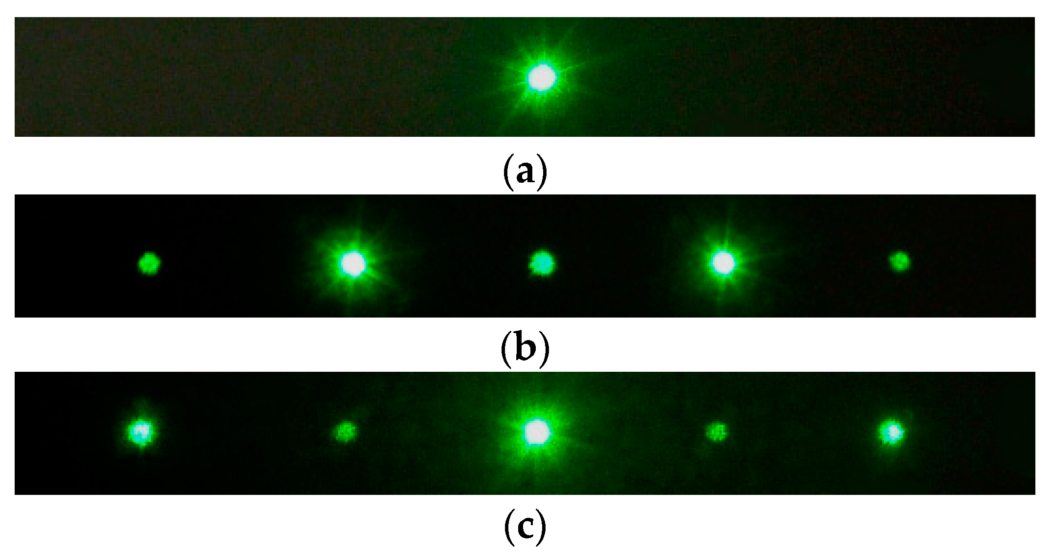
The diffraction pattern produced by the template grating (the CDW acting as polarization modulator) has small leakage (1.4%), and also exhibits second-order diffracted beams that would be absent in an ideal grating, Figure 7a. The printed component shows high efficiency at twice the diffraction angle, Figure 7b. Almost 70% of light is, however, “leaking” onto the 0th diffraction angle, since the thickness of the LC cell with no spacers could not be tuned to the half-wave retardation condition for the test beam of 532 nm wavelength. Table 1 summarizes the diffraction efficiency of template and printed gratings.
The data in Table 1 correspond to the LC CDW right after printing and filling the cell with the LC. The diffraction efficiency greatly improved, nearly tripling, after 1 h. The orientation of LC improved with time due to the annihilation of the disclinations typically observed when making nonuniformly aligned cells. The diffraction efficiencies were calculated with respect to the incident beam power. The total transmission for both CDWs are high, 86.3% for the template CDW and 77.8% for the printed CDW at 532 nm wavelength. Most losses are due to Fresnel reflections, and no haze, which is typical of poor-quality polarization gratings, is noticeable [18].
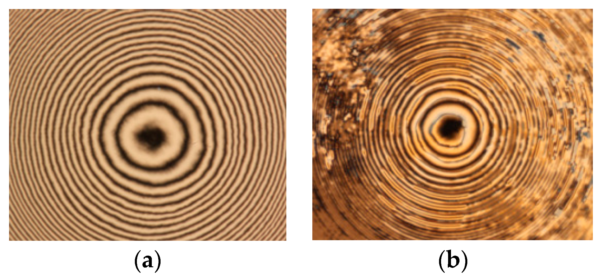
A second test structure, a diffractive waveplate lens, was also printed using a single pulse in a LC cell made with PAAD-72 coated substrates and 6 μm spacers. The cell was pre-aligned with linearly polarized He-Cd laser (λ = 442 nm), exposed to the nanosecond pulse, and then filled with a low birefringence BEAM Co. LC R-237 (Δn = 0.058 at 532 nm). A LCP diffractive waveplate lens of 4 mm diameter and 12.5 mm focal length was prepared and used as the template spatial polarization modulator tuned to half-wave retardation condition for λ = 532 nm wavelength. Figure 8 shows the lens printed with a single pulse of 1.2 J/cm2 energy density. The spacing of the anisotropy axis modulation in the printed lens was measured to be 13 μm at 250 μm distance from the axis. Beyond this range, the NLC alignment is lost due to the violation of the stability condition discussed above. The calculated focal length of the printed lens was 6 mm for 532 nm wavelength, twice as small as the focal length of the template lens as expected.
5. Conclusions
The anisotropic order induced by short nanosecond laser pulses in azobenzene-based thin film coatings is strong enough to orient adjacent layers of liquid crystalline materials with high spatial resolution. The process dynamics were explored using a planar-twist cell configuration, and then two such structures were formulated using diffractive waveplate templates. The opportunity to print diffractive waveplates with a nanosecond pulse opens up avenues for manufacturing optical components quickly and inexpensively enough for large-scale production. The resolution and quality of the 4G optical components can be improved by improving the beam quality of the pulsed lasers and by using projection schemes that mitigate beam divergence effect. The current development also opens up opportunities for fundamental study of liquid crystal alignment at interfaces with fast-changing easy axis orientation.
Acknowledgments
This work was supported by the US AFRL. The authors are grateful to Michael E. McConney, T.J. White, B.R. Kimball, and D.M. Steeves for discussion of different aspects of the study.
Author Contributions
Svetlana Serak performed the experiments. Timothy J. Bunning guided the study. Nelson V. Tabiryan conceived and designed the experiments.
Conflicts of Interest
The authors declare no conflict of interest.
References
- Tabiryan, N.; Roberts, D.; Steeves, D.; Kimball, B. 4G Optics: New technology extends limits to the extremes. Photonics Spectra 2017, 51, 46–50. [Google Scholar]
- Tabiryan, N.V.; Nersisyan, S.R.; Steeves, D.M.; Kimball, B.R. The promise of diffractive waveplates. Opt. Photonics News 2010, 21, 41–45. [Google Scholar]
- Tabiryan, N.V.; Roberts, D.; Serabyn, E.; Steeves, D.; Kimball, B. Superlens in the skies: Liquid-crystal-polymer technology for telescopes. SPIE Newsroom 2016. [Google Scholar] [CrossRef]
- Tabiryan, N.V.; Serak, S.V.; Nersisyan, S.R.; Roberts, D.E.; Zeldovich, B.Y.; Steeves, D.M.; Kimball, B.R. Broadband waveplate lenses. Opt. Express 2016, 24, 7091–7102. [Google Scholar] [CrossRef] [PubMed]
- Tabiryan, N.V.; Serak, S.V.; Roberts, D.E.; Steeves, D.M.; Kimball, B.R. Thin waveplate lenses of switchable focal length new generation in optics. Opt. Express 2015, 23, 25783–25794. [Google Scholar] [CrossRef] [PubMed]
- Woon, K.L.; O’Neill, M.; Vlachos, P.; Aldred, M.P.; Kelly, S.M. Highly birefringent nematic and chiral nematic liquid crystals. Liq. Cryst. 2005, 23, 1191–1194. [Google Scholar] [CrossRef]
- Dąbrowski, R.; Kula, P.; Herman, J. High birefringence liquid crystals. Crystals 2013, 3, 443–482. [Google Scholar] [CrossRef]
- Chigrinov, V.G.; Kozenkov, V.M.; Kwok, H.S. Photoaligning: Physics and Applications in Liquid Crystal Devices; Wiley VCH: Weinheim, Germany, 2008. [Google Scholar]
- Ichimura, K. Photoalignment of liquid-crystal systems. Chem. Rev. 2000, 100, 1847–1873. [Google Scholar] [CrossRef] [PubMed]
- Nersisyan, S.R.; Tabiryan, N.V.; Steeves, D.M.; Kimball, B. Optical axis gratings in liquid crystals and their use for polarization insensitive optical switching. J. Nonlinear Opt. Phys. 2009, 18, 1–47. [Google Scholar] [CrossRef]
- Nikolova, L.; Ramanujam, P.S. Polarization Holography; Cambridge University Press: Cambridge, UK, 2009. [Google Scholar]
- Nersisyan, S.R.; Tabiryan, N.V.; Mawet, D.; Serabyn, E. Improving vector vortex waveplates for high contrast coronagraphy. Opt. Express 2013, 21, 8205–8213. [Google Scholar] [CrossRef] [PubMed]
- Nersisyan, S.R.; Tabiryan, N.V.; Steeves, D.M.; Kimball, B.R. Fabrication of liquid crystal polymer axial waveplates for UV-IR wavelengths. Opt. Express 2009, 17, 11926–11934. [Google Scholar] [CrossRef] [PubMed]
- De Sio, L.; Roberts, D.; Liao, Z.; Nersisyan, S.; Uskova, O.; Wickboldt, L.; Tabiryan, N.; Steeves, D.; Kimball, B. Digital polarization holography advancing geometrical phase optics. Opt. Express 2016, 24, 18297–18306. [Google Scholar] [CrossRef] [PubMed]
- Dabrovski, R. Isothiocyanates and their mixtures with a broad range of nematic phase. Mol. Cryst. Liq. Cryst. 1990, 191, 17–27. [Google Scholar]
- Nersisyan, S.R.; Tabiryan, N.V.; Steeves, D.M.; Kimball, B.R. Characterization of optically imprinted polarization gratings. Appl. Opt. 2009, 48, 4062–4067. [Google Scholar] [CrossRef] [PubMed]
- Sarkissian, H.; Tabirian, N.; Park, B.; Zeldovich, B. Periodically aligned liquid crystal: Potential application for projection displays. Mol. Cryst. Liq. Cryst. 2006, 451, 1–19. Available online: http://oai.dtic.mil/oai/oai?verb=getRecord&metadataPrefix=html&identifier=ADA428000 (accessed on 10 August 2004). [CrossRef]
- Crawford, G.P.; Eakin, J.N.; Radcliffe, M.D.; Callan-Jones, A.; Pelcovits, R.A. Liquid-crystal diffraction gratings using polarization holography alignment techniques. J. Appl. Phys. 2005, 98, 123102. [Google Scholar] [CrossRef]
Figure 1.
Schematic of the test setup: DBS, dichroic beam splitter; DM, dichroic mirror; DF, dichroic filter; PD1, PD2, photodetectors; L1, L2, L3, lenses with focal lengths of 400 mm, 150 mm, and 80 mm, correspondingly; NDF, set of neutral density filters; EM, energy meter; P, probe beam polarizer; A, probe beam analyzer; PB, pump block filter. The inset shows the profile of a single ns pulse of Δt1/2 = 6.5 ns duration and 10 mJ power.

Figure 2.
Absorption spectra of 1 wt.% solution of PAAD materials in DMF.

Figure 3.
(a,b) LC cell orientation (a) before and (b) after exposure to cw radiation. (c,d) Photos of twist LC orientation area induced with Argon-ion laser beam (λ = 514 nm, I = 0.5 W/cm2, t = 10 s) for PAAD-72/PVA cell between (c) parallel and (d) crossed polarizers. (e,f) Transmission dynamics through 6-μm thick LC cell between parallel polarizers for exposure wavelengths (e) 457 nm and (f) 514 nm.

Figure 4.
Photoalignment of LC cells of 6-μm thickness induced with single ns pulses. (a,b) PAAD-72/PVA cell, λ = 532 nm, E = 0.71 J/cm2, d = 1.2 mm. (c,d) PAAD-22/PVA cell; λ = 355 nm, E = 0.18 J/cm2, d = 1.2 mm. (e,f) PAAD-72/PAAD-72 cell; λ = 532 nm, E = 2.6 J/cm2, d = 0.8 mm. (g,h) PAAD-27/PVA cell, series of four 7.5 ns pulses at 0.1 Hz frequency; λ = 532 nm, E = 1.1 J/cm2, d = 0.9 mm. Figures with black (white) background correspond to LC cells between crossed (parallel) polarizers.
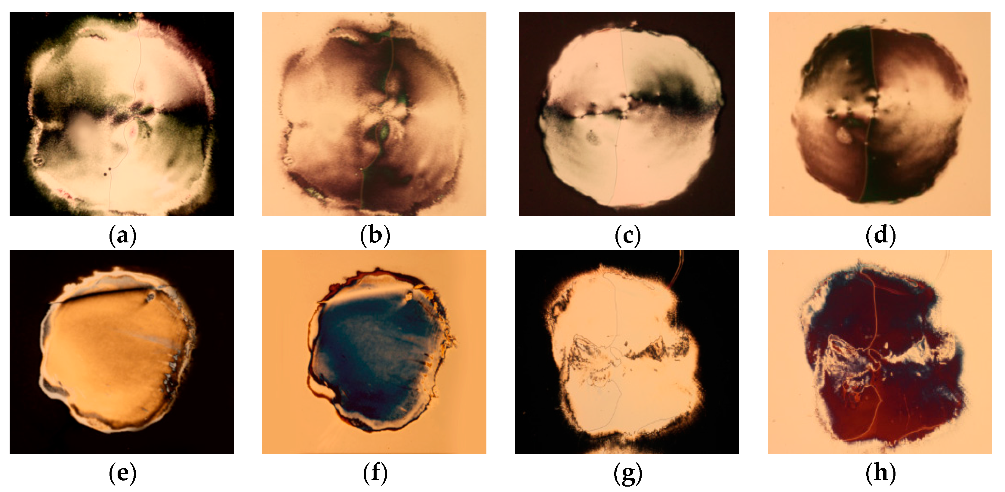
Figure 5.
(a–d) Transmission dynamics at different time scales. (e) Accumulation effect for several pulses.
Figure 5.
(a–d) Transmission dynamics at different time scales. (e) Accumulation effect for several pulses.
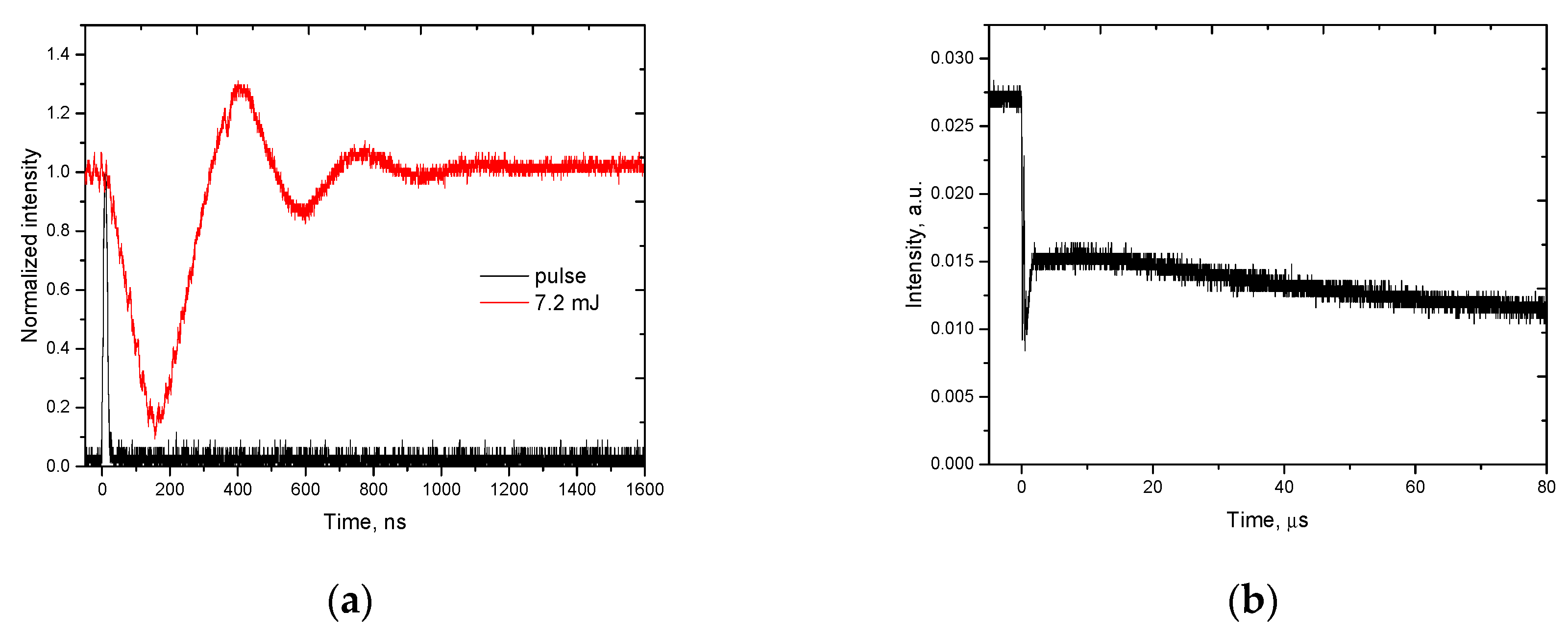

Figure 6.
(a) Schematic of a cycloidal orientation pattern in a LC; (b) polarizing microscope image (100× objective) of a cycloidal polarization grating of 2.5 μm period printed with a single 6.7 ns pulse of 0.85 J/cm2 exposure energy.
Figure 6.
(a) Schematic of a cycloidal orientation pattern in a LC; (b) polarizing microscope image (100× objective) of a cycloidal polarization grating of 2.5 μm period printed with a single 6.7 ns pulse of 0.85 J/cm2 exposure energy.
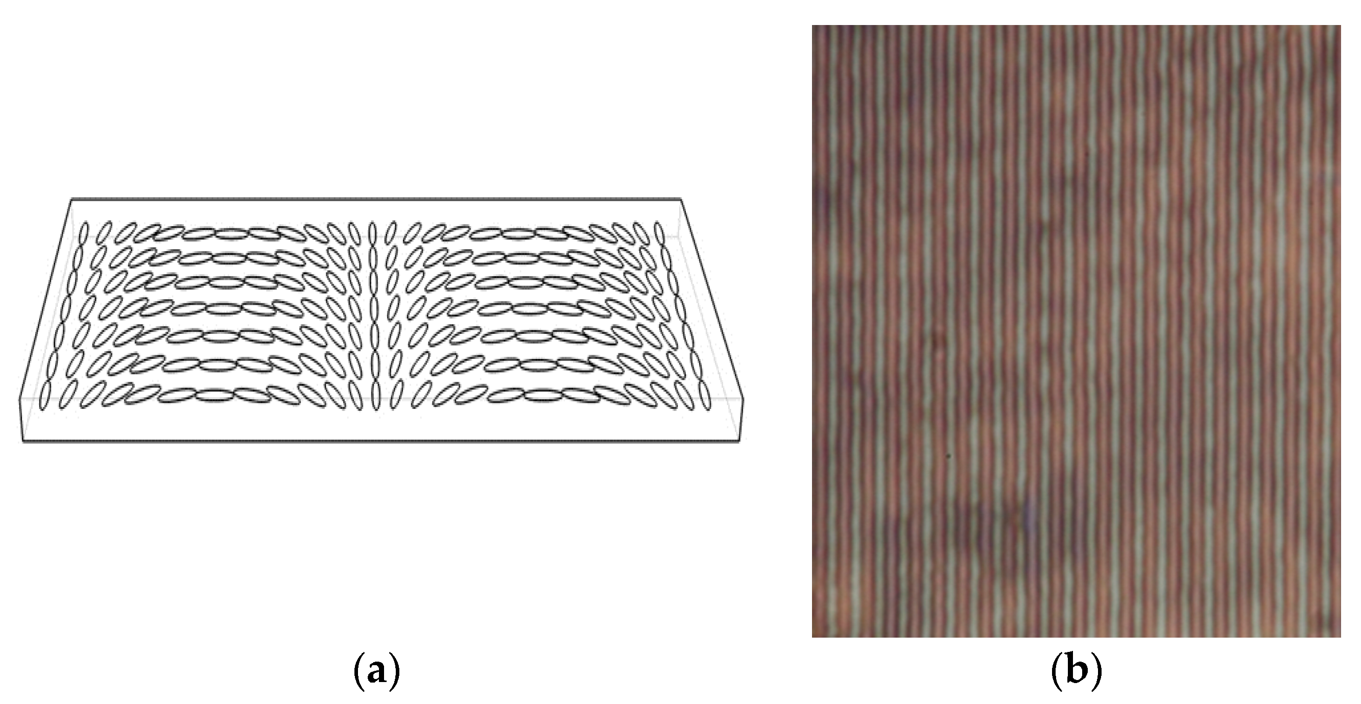
Figure 7.
Photos of diffraction patterns on a screen: (a) the incident laser beam, (b) diffraction on template LCP CDW; (c) diffraction on printed LC CDW.
Figure 7.
Photos of diffraction patterns on a screen: (a) the incident laser beam, (b) diffraction on template LCP CDW; (c) diffraction on printed LC CDW.

Figure 8.
Polarizing microscope images (20X objective) of the template LCP diffractive waveplate lens (a) and the lenses recorded with single (b) and ns pulses. Photos were taken between polarizers.
Figure 8.
Polarizing microscope images (20X objective) of the template LCP diffractive waveplate lens (a) and the lenses recorded with single (b) and ns pulses. Photos were taken between polarizers.


Table 1.
Diffraction efficiency of the template and printed CDWs at different angles.
| P−2/Pin | P−1/Pin | P0/Pin | P+1/Pin | P+2/Pin | |
|---|---|---|---|---|---|
| Template CDW | 0.5% | 44.6% | 1.4% | 39.6% | 0.2% |
| LC CDW | 4.1% | 0.8% | 69.7% | 0.4% | 2.8% |
© 2017 by the authors. Licensee MDPI, Basel, Switzerland. This article is an open access article distributed under the terms and conditions of the Creative Commons Attribution (CC BY) license (http://creativecommons.org/licenses/by/4.0/).
Share and Cite
MDPI and ACS Style
Serak, S.V.; Bunning, T.J.; Tabiryan, N.V. Ultrafast Photoalignment: Recording a Lens in a Nanosecond. Crystals 2017, 7, 338. https://doi.org/10.3390/cryst7110338
AMA Style
Serak SV, Bunning TJ, Tabiryan NV. Ultrafast Photoalignment: Recording a Lens in a Nanosecond. Crystals. 2017; 7(11):338. https://doi.org/10.3390/cryst7110338
Chicago/Turabian StyleSerak, Svetlana V., Timothy J. Bunning, and Nelson V. Tabiryan. 2017. "Ultrafast Photoalignment: Recording a Lens in a Nanosecond" Crystals 7, no. 11: 338. https://doi.org/10.3390/cryst7110338
Note that from the first issue of 2016, this journal uses article numbers instead of page numbers. See further details here.