
Chiral Optical Tamm States: Temporal Coupled-Mode Theory

 ,
, 
 and
and 
Abstract
:1. Introduction
A Method to Describe Spectral Peaks
2. Model
Maxwell Equations in the Basis Associated with the Cholesteric Director
3. Solution without the Low-Anisotropy Approximation
3.1. The Case of Equal Anisotropies,
3.2. The Case of Unequal Anisotropies,
4. Relaxation Time and Spectral Manifestation
4.1. Temporal Coupled-Mode Theory
4.2. TCMT Applicability Limits
4.3. Numerical Results
5. Conclusions
Acknowledgments
Author Contributions
Conflicts of Interest
Abbreviations
| COTS | chiral optical Tamm state |
| TCMT | temporal coupled-mode theory |
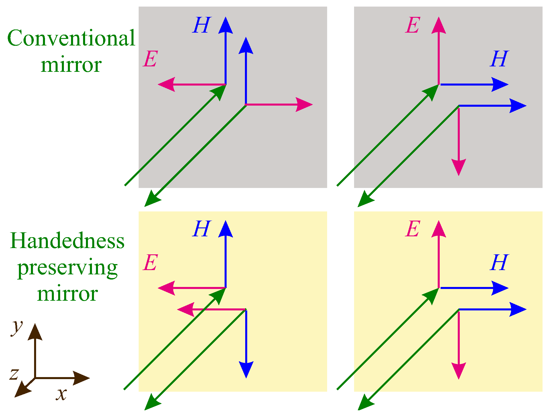
| HPM | handedness-preserving mirror |
References
- Belyakov, V.A. Diffraction Optics of Complex-Structured Periodic Media; Springer: New York, NY, USA, 1992; p. 352. [Google Scholar]
- Faryad, M.; Lakhtakia, A. The circular Bragg phenomenon. Adv. Opt. Photonics 2014, 6, 225. [Google Scholar] [CrossRef]
- Xiang, J.; Li, Y.; Li, Q.; Paterson, D.A.; Storey, J.M.D.; Imrie, C.T.; Lavrentovich, O.D. Electrically Tunable Selective Reflection of Light from Ultraviolet to Visible and Infrared by Heliconical Cholesterics. Adv. Mater. 2015, 27, 3014–3018. [Google Scholar] [CrossRef] [PubMed]
- Avendaño, C.G.; Ponti, S.; Reyes, J.A.; Oldano, C. Multiplet structure of the defect modes in 1D helical photonic crystals with twist defects. J. Phys. A Math. Gen. 2005, 38, 8821–8840. [Google Scholar] [CrossRef]
- Haus, H.; Shank, C. Antisymmetric taper of distributed feedback lasers. IEEE J. Quantum Electron. 1976, 12, 532–539. [Google Scholar] [CrossRef]
- Lakhtakia, A.; McCall, M. Sculptured thin films as ultranarrow-bandpass circular-polarization filters. Opt. Commun. 1999, 168, 457–465. [Google Scholar] [CrossRef]
- Yang, Y.C.; Kee, C.S.; Kim, J.E.; Park, H.Y.; Lee, J.C.; Jeon, Y.J. Photonic defect modes of cholesteric liquid crystals. Phys. Rev. E 1999, 60, 6852–6854. [Google Scholar] [CrossRef]
- Shabanov, A.V.; Vetrov, S.Y.; Karneev, A.Y. Reflection spectrum of a cholesteric liquid crystal with structural defects. J. Exp. Theor. Phys. Lett. 2004, 80, 181–184. [Google Scholar] [CrossRef]
- Gevorgyan, A.H. The loss of the polarization dependence of diffraction reflection in chiral photonic crystals in the presence of anisotropic defects. Tech. Phys. Lett. 2006, 32, 698–702. [Google Scholar] [CrossRef]
- Belyakov, V.A.; Semenov, S.V. Optical defect modes in chiral liquid crystals. J. Exp. Theor. Phys. 2011, 112, 694–710. [Google Scholar] [CrossRef]
- Kiselev, A.D.; Chigrinov, V.G. Optics of short-pitch deformed-helix ferroelectric liquid crystals: Symmetries, exceptional points, and polarization-resolved angular patterns. Phys. Rev. E 2014, 90, 042504. [Google Scholar] [CrossRef] [PubMed]
- Hsiao, Y.C.; Wang, H.T.H.T.; Lee, W. Thermodielectric generation of defect modes in a photonic liquid crystal. Opt. Express 2014, 22, 3593–3599. [Google Scholar] [CrossRef] [PubMed]
- Rodarte, A.; Cisneros, F.; Hein, J.; Ghosh, S.; Hirst, L. Quantum Dot/Liquid Crystal Nanocomposites in Photonic Devices. Photonics 2015, 2, 855–864. [Google Scholar] [CrossRef]
- Lin, J.D.; Chu, C.L.; Lin, H.Y.; You, B.; Horng, C.T.; Huang, S.Y.; Mo, T.S.; Huang, C.Y.; Lee, C.R. Wide-band tunable photonic bandgaps based on nematic-refilling cholesteric liquid crystal polymer template samples. Opt. Mater. Express 2015, 5, 1419. [Google Scholar] [CrossRef]
- Kesaev, V.V.; Pozhidaev, E.P.; Kiselev, A.D. Modulation of unpolarized light in planar aligned subwavelength-pitch deformed-helix ferroelectric liquid crystals. Phys. Rev. E 2017, 95, 032705. [Google Scholar] [CrossRef]
- Hodgkinson, I.J.; Wu, Q.H.; Thorn, K.E.; Lakhtakia, A.; McCall, M.W. Spacerless circular-polarization spectral-hole filters using chiral sculptured thin films: Theory and experiment. Opt. Commun. 2000, 184, 57–66. [Google Scholar] [CrossRef]
- Kopp, V.I.; Genack, A.Z. Twist Defect in Chiral Photonic Structures. Phys. Rev. Lett. 2002, 89, 033901. [Google Scholar] [CrossRef] [PubMed]
- Oldano, C.; Reyes, J.A.; Ponti, S. Twist defects in helical sonic structures. Phys. Rev. E 2003, 67, 056624. [Google Scholar] [CrossRef] [PubMed]
- Becchi, M.; Ponti, S.; Reyes, J.; Oldano, C. Defect modes in helical photonic crystals: An analytic approach. Phys. Rev. B 2004, 70, 033103. [Google Scholar] [CrossRef]
- Schmidtke, J.; Stille, W. Photonic defect modes in cholesteric liquid crystal films. Eur. Phys. J. E Soft Matter 2003, 12, 553–564. [Google Scholar] [CrossRef] [PubMed]
- Schmidtke, J.; Stille, W.; Finkelmann, H. Defect Mode Emission of a Dye Doped Cholesteric Polymer Network. Phys. Rev. Lett. 2003, 90, 083902. [Google Scholar] [CrossRef] [PubMed]
- Ozaki, M.; Ozaki, R.; Matsui, T.; Yoshino, K. Twist-Defect-Mode Lasing in Photopolymerized Cholesteric Liquid Crystal. Jpn. J. Appl. Phys. 2003, 42, L472–L475. [Google Scholar] [CrossRef]
- Oldano, C. Comment on “Twist Defect in Chiral Photonic Structures”. Phys. Rev. Lett. 2003, 91, 259401. [Google Scholar] [CrossRef] [PubMed]
- Kopp, V.; Genack, A. Kopp and Genack Reply. Phys. Rev. Lett. 2003, 91, 259402. [Google Scholar] [CrossRef]
- Gevorgyan, A.H.; Rafayelyan, M.S. Optics of anisotropic metamaterial based structurally chiral photonic crystals. J. Opt. 2013, 15, 125103. [Google Scholar] [CrossRef]
- McCall, M.W.; Hodgkinson, I.J.; Wu, Q. Birefringent Thin Films and Polarizing Elements: 2nd Edition, 2nd revise ed.; Imperial College Press: London, UK, 2015. [Google Scholar]
- Belyakov, V.A.; Shilina, G.I. Surface Guided Electromagnetic Waves of Higher Diffraction Orders in Cholesterics. Mol. Cryst. Liq. Cryst. 1992, 223, 55–67. [Google Scholar] [CrossRef]
- Kavokin, A.; Shelykh, I.; Malpuech, G. Optical Tamm states for the fabrication of polariton lasers. Appl. Phys. Lett. 2005, 87, 261105. [Google Scholar] [CrossRef]
- Vinogradov, A.P.; Dorofeenko, A.V.; Merzlikin, A.M.; Lisyansky, A.A. Surface states in photonic crystals. Uspekhi Fizicheskikh Nauk 2010, 53, 243–256. [Google Scholar] [CrossRef]
- Iorsh, I.V.; Belov, P.A.; Zharov, A.A.; Shadrivov, I.V.; Kivshar, Y.S. Nonlinear Tamm states in nanostructured plasmonic metamaterials. Phys. Rev. A 2012, 86, 023819. [Google Scholar] [CrossRef]
- Afinogenov, B.I.; Bessonov, V.O.; Nikulin, A.A.; Fedyanin, A.A. Observation of hybrid state of Tamm and surface plasmon-polaritons in one-dimensional photonic crystals. Appl. Phys. Lett. 2013, 103, 061112. [Google Scholar] [CrossRef]
- Auguié, B.; Bruchhausen, A.; Fainstein, A. Critical coupling to Tamm plasmons. J. Opt. 2015, 17, 035003. [Google Scholar] [CrossRef]
- Chang, C.Y.; Chen, Y.H.; Tsai, Y.L.; Kuo, H.C.; Chen, K.P. Tunability and optimization of coupling efficiency in tamm plasmon modes. IEEE J. Sel. Top. Quantum Electron. 2015, 21, 4600206. [Google Scholar] [CrossRef]
- Yang, Z.Y.; Ishii, S.; Yokoyama, T.; Dao, T.D.; Sun, M.g.; Nagao, T.; Chen, K.P. Tamm plasmon selective thermal emitters. Opt. Lett. 2016, 41, 4453. [Google Scholar] [CrossRef] [PubMed]
- Kaliteevski, M.; Iorsh, I.; Brand, S.; Abram, R.A.; Chamberlain, J.M.; Kavokin, A.V.; Shelykh, I.A. Tamm plasmon-polaritons: Possible electromagnetic states at the interface of a metal and a dielectric Bragg mirror. Phys. Rev. B 2007, 76, 165415. [Google Scholar] [CrossRef]
- Abdulhalim, I. Unique optical properties of anisotropic helical structures in a Fabry-Perot cavity. Opt. Lett. 2006, 31, 3019. [Google Scholar] [CrossRef] [PubMed]
- Timofeev, I.V.; Arkhipkin, V.G.; Vetrov, S.Y.; Zyryanov, V.Y.; Lee, W. Enhanced light absorption with a cholesteric liquid crystal layer. Opt. Mater. Express 2013, 3, 496. [Google Scholar] [CrossRef]
- Vetrov, S.Y.; Pyatnov, M.V.; Timofeev, I.V. Surface modes in “photonic cholesteric liquid crystal–phase plate–metal” structure. Opt. Lett. 2014, 39, 2743–2746. [Google Scholar] [CrossRef] [PubMed]
- Vetrov, S.Y.; Pyatnov, M.V.; Timofeev, I.V. Spectral and polarization properties of a ‘cholesteric liquid crystal—phase plate—metal’ structure. J. Opt. 2016, 18, 015103. [Google Scholar] [CrossRef]
- Zhuang, Z.; Patel, J.S. Behavior of cholesteric liquid crystals in a Fabry–Perot cavity. Opt. Lett. 1999, 24, 1759. [Google Scholar] [CrossRef] [PubMed]
- Isaacs, S.; Placido, F.; Abdulhalim, I. Investigation of liquid crystal Fabry–Perot tunable filters: Design, fabrication, and polarization independence. Appl. Opt. 2014, 53, H91. [Google Scholar] [CrossRef] [PubMed]
- Hsiao, Y.C.; Hou, C.T.C.T.; Zyryanov, V.Y.; Lee, W. Multichannel photonic devices based on tristable polymer-stabilized cholesteric textures. Opt. Express 2011, 19, 23952. [Google Scholar] [CrossRef] [PubMed]
- Timofeev, I.V.; Lin, Y.T.; Gunyakov, V.A.; Myslivets, S.A.; Arkhipkin, V.G.; Vetrov, S.Y.; Lee, W.; Zyryanov, V.Y. Voltage-induced defect mode coupling in a one-dimensional photonic crystal with a twisted-nematic defect layer. Phys. Rev. E 2012, 85, 011705. [Google Scholar] [CrossRef] [PubMed]
- Timofeev, I.V.; Vetrov, S.Y. Chiral optical Tamm states at the boundary of the medium with helical symmetry of the dielectric tensor. JETP Lett. 2016, 104, 380–383. [Google Scholar] [CrossRef]
- Gunyakov, V.A.; Krakhalev, M.; Zyryanov, V.; Shabanov, V.; Loiko, V. Modulation of defect modes intensity by controlled light scattering in photonic crystal with liquid crystal domain structure. J. Quant. Spectrosc. Radiat. Transf. 2016, 178, 152–157. [Google Scholar] [CrossRef]
- Huang, K.C.; Hsiao, Y.C.; Timofeev, I.V.; Zyryanov, V.Y.; Lee, W. Photo-manipulated photonic bandgap devices based on optically tristable chiral-tilted homeotropic nematic liquid crystal. Opt. Express 2016, 24, 25019. [Google Scholar] [CrossRef] [PubMed]
- Plum, E.; Zheludev, N.I. Chiral mirrors. Appl. Phys. Lett. 2015, 106, 221901. [Google Scholar] [CrossRef]
- Fedotov, V.; Rogacheva, A.; Schwanecke, A.; Mladyonov, R.; Prosvirnin, S.; Cheni, Y.; Zheludev, N. ’Miracle’ mirror that does not change the phase of reflected wave. In Proceedings of the 2005 IEEE LEOS Annual Meeting Conference Proceedings, Sydney, Australia, 22–28 October 2005; Volume 2005, pp. 539–540. [Google Scholar]
- Ding, F.; Wang, Z.; He, S.; Shalaev, V.M.; Kildishev, A.V. Broadband high-efficiency half-wave plate: A supercell-based plasmonic metasurface approach. ACS Nano 2015, 9, 4111–4119. [Google Scholar] [CrossRef] [PubMed]
- Rudakova, N.V.; Timofeev, I.V.; Pankin, P.S.; Vetrov, S.Y. Polarization-Preserving Anisotropic Mirror on the Basis of Metal–Dielectric Nanocomposite. Bull. Russ. Acad. Sci. Phys. 2017, 81, 10–14. [Google Scholar] [CrossRef]
- Berreman, D.W. Optics in Stratified and Anisotropic Media: 4 x 4-Matrix Formulation. J. Opt. Soc. Am. 1972, 62, 502. [Google Scholar] [CrossRef]
- Oseen, C. The theory of liquid crystals. Trans. Faraday Soc. 1933, 29, 883–889. [Google Scholar] [CrossRef]
- De Vries, H. Rotatory power and other optical properties of certain liquid crystals. Acta Crystallogr. 1951, 4, 219–226. [Google Scholar] [CrossRef]
- Kats, E. Optical properties of cholesteric liquid crystals. J. Exp. Theor. Phys. 1971, 32, 1004–1007. [Google Scholar]
- Nityananda, R. On the Theory of Light Propagation in Cholesteric Liquid Crystals. Mol. Cryst. Liq. Cryst. 1973, 21, 315–331. [Google Scholar] [CrossRef]
- Haus, H.A. Waves and Fields in Optoelectronics; Prentice-Hall Series in Solid State Physical Electronics; Prentice Hall, Incorporated: Upper Saddle River, NJ, USA, 1983; p. 402. [Google Scholar]
- Manolatou, C.; Haus, H.A. Passive Components for Dense Optical Integration; Springer: Berlin, Germany, 2002; p. 173. [Google Scholar]
- Joannopoulos, J.D.; Johnson, S.G.; Winn, J.N.; Meade, R.D. Photonic Crystals: Molding the Flow of Light, 2nd ed.; Princeton University Press: Princeton, NJ, USA, 2008; p. 304. [Google Scholar]
- Fan, S.; Suh, W.; Joannopoulos, J.D. Temporal coupled-mode theory for the Fano resonance in optical resonators. J. Opt. Soc. Am. A 2003, 20, 569. [Google Scholar] [CrossRef]
- Xu, Y.; Li, Y.; Lee, R.K.; Yariv, A. Scattering-theory analysis of waveguide-resonator coupling. Phys. Rev. E 2000, 62, 7389–7404. [Google Scholar] [CrossRef]
- Bliokh, K.Y.; Bliokh, Y.P.; Freilikher, V.; Savel’ev, S.; Nori, F. Colloquium : Unusual resonators: Plasmonics, metamaterials, and random media. Rev. Mod. Phys. 2008, 80, 1201–1213. [Google Scholar] [CrossRef]
- Lippmann, B.A.; Schwinger, J. Variational Principles for Scattering Processes. I. Phys. Rev. 1950, 79, 469–480. [Google Scholar] [CrossRef]
- Kogelnik, H. Coupled Wave Theory for Thick Hologram Gratings. Bell Syst. Tech. J. 1969, 48, 2909–2947. [Google Scholar] [CrossRef]
- Yariv, A. Coupled-mode theory for guided-wave optics. IEEE J. Quantum Electron. 1973, 9, 919–933. [Google Scholar] [CrossRef]
- Barybin, A.A.; Dmitriev, V.A. Modern Electrodynamics and Coupled-Mode Theory: Application To Guided-Wave Optics; Rinton Press: Princeton, NJ, USA, 2002. [Google Scholar]
- Belyakov, V.A.; Dmitrienko, V.E. Theory of the optical properties of cholesteric liquid crystals. Sov. Phys. Solid State 1974, 15, 1811–1815. [Google Scholar]
- Belyakov, V.A.; Orlov, V.P.; Shilina, G.I. Surface guided electromagnetic modes in films with periodically modulated characteristics. J. Exp. Theor. Phys. 1992, 75, 189–194. [Google Scholar]
- McCall, M.W.; Lakhtakia, A. Development and assessment of coupled wave theory of axial propagation in thin-film helicoidal bianisotropic media. Part 1: Reflectances and transmittances. J. Mod. Opt. 2000, 47, 973–991. [Google Scholar] [CrossRef]
- Wang, F.; Lakhtakia, A. Optical crossover phenomenon due to a central 90-twist defect in a chiral sculptured thin film or chiral liquid crystal. Proc. R. Soc. A Math. Phys. Eng. Sci. 2005, 461, 2985–3004. [Google Scholar] [CrossRef]
- Pierce, J.R. Coupling of modes of propagation. J. Appl. Phys. 1954, 25, 179–183. [Google Scholar] [CrossRef]
- Manolatou, C.; Khan, M.; Fan, S.; Villeneuve, P.; Haus, H.; Joannopoulos, J.D. Coupling of modes analysis of resonant channel add-drop filters. IEEE J. Quantum Electron. 1999, 35, 1322–1331. [Google Scholar] [CrossRef]


© 2017 by the authors. Licensee MDPI, Basel, Switzerland. This article is an open access article distributed under the terms and conditions of the Creative Commons Attribution (CC BY) license (http://creativecommons.org/licenses/by/4.0/).
Share and Cite
Timofeev, I.V.; Pankin, P.S.; Vetrov, S.Y.; Arkhipkin, V.G.; Lee, W.; Zyryanov, V.Y. Chiral Optical Tamm States: Temporal Coupled-Mode Theory. Crystals 2017, 7, 113. https://doi.org/10.3390/cryst7040113
Timofeev IV, Pankin PS, Vetrov SY, Arkhipkin VG, Lee W, Zyryanov VY. Chiral Optical Tamm States: Temporal Coupled-Mode Theory. Crystals. 2017; 7(4):113. https://doi.org/10.3390/cryst7040113
Chicago/Turabian StyleTimofeev, Ivan V., Pavel S. Pankin, Stepan Ya. Vetrov, Vasily G. Arkhipkin, Wei Lee, and Victor Ya. Zyryanov. 2017. "Chiral Optical Tamm States: Temporal Coupled-Mode Theory" Crystals 7, no. 4: 113. https://doi.org/10.3390/cryst7040113
APA StyleTimofeev, I. V., Pankin, P. S., Vetrov, S. Y., Arkhipkin, V. G., Lee, W., & Zyryanov, V. Y. (2017). Chiral Optical Tamm States: Temporal Coupled-Mode Theory. Crystals, 7(4), 113. https://doi.org/10.3390/cryst7040113