Morphology Transition of ZnO Nanorod Arrays Synthesized by a Two-Step Aqueous Solution Method


1
Guangdong Provincial Key Laboratory of Quantum Engineering and Quantum Materials, South China Normal University, Guangzhou 510006, Guangdong, China
2
Guangdong Engineering Technology Research Center of Efficient Green Energy and Environmental Protection Materials, Guangzhou 510006, Guangdong, China
3
Department of Electronic Engineering, Jinan University, Guangzhou 510632, Guangdong, China
4
Whiting School of Engineering, Johns Hopkins University, 3400 North Charles Street, Baltimore, MD 21218-2608, USA
5
Institute of Materials Research and Engineering, A*STAR (Agency for Science, Technology and Research), 2 Fusionopolis Way, Innovis, Singapore 138634, Singapore
*
Authors to whom correspondence should be addressed.
Crystals 2018, 8(4), 152; https://doi.org/10.3390/cryst8040152
Submission received: 21 February 2018
/
Revised: 23 March 2018
/
Accepted: 27 March 2018
/
Published: 30 March 2018
(This article belongs to the Special Issue Crystal Chemistry of Zinc, Cadmium and Mercury)
Abstract
:ZnO nanorod arrays (ZNAs) with vertically-aligned orientation were obtained by a two-step aqueous solution method. The morphology of the ZnO nanorods was regulated by changing the precursor concentration and the growth time of each step. ZnO nanorods with distinct structures, including flat top, cone top, syringe shape, and nail shape, were obtained. Moreover, based on the X-ray diffraction (XRD) and the transmission electron microscope (TEM) analysis, the possible growth mechanisms of different ZnO nanostructrues were proposed. The room-temperature PL spectra show that the syringe-shaped ZNAs with ultra-sharp tips have high crystalline quality. Our study provides a simple and repeatable method to regulate the morphology of the ZNAs.
1. Introduction
In recent years, one-dimensional nanostructures, like nanorods, nanotubes, and nanowires, have attracted much more attention, due to their potential applications on the nanodevices, such as sensors, field emission, and detectors, etc. [1,2,3,4,5,6,7,8]. Among them, ZnO, as an important II–VI semiconductor with a direct band gap of 3.37 eV, larger exciton binding energy of 60 mV [9,10] at room temperature, and piezoelectricity [11], has attracted special interest. Especially, vertically aligned ZnO nanorod arrays (ZNAs), due to their non-toxicity, low-cost, large surface to volume ratio, and ease of large scale fabrication, can be employed in many devices, like solar cells, UV lasers, gas sensors, UV detectors, and photocatalysis [12,13,14,15,16,17,18,19,20]. Various methods have been used to synthesize ZNAs, including chemical vapor deposition (CVD) [21,22], pulsed laser deposition (PLD) [23], molecular beam epitaxy (MBE) [10,24], etc. Compared to these methods, the aqueous solution method [25,26] has emerged more recently, which paves a facile way to obtain preferred-aligned ZNAs on various substrates just by pre-coating a ZnO seed layer. Furthermore, the aqueous solution method is always conducted under low temperature (<95 °C), which extends its application on the temperature-sensitive substrates. However, until now, exact control over the morphologies of ZnO nanostructure during the solution growth is still a challenge, especially for some sophisticated structures. Furthermore, the growth mechanisms of ZnO nanostructures in solution are far from fully understood.
In this article, we proposed a two-step aqueous solution method to obtain preferred orientation ZNAs. The morphologies of the ZnO nanorods were regulated by changing the precursor concentration and the growth time in each step. ZnO nanorods with distinct structures, including flat top, cone top, syringe shape, and nail shape, were obtained. Moreover, based on the X-ray diffraction (XRD) and the transmission electron microscope (TEM) characterizations, the possible growth mechanisms of different ZnO nanostructrues were proposed. Our study allows to understand the growth mechanisms of the ZNAs with different morphologies in depth, and provides a simple and repeatable method to regulate the morphology of the ZNAs.
2. Materials and Methods
2.1. Substrate Preparation
Multi-crystalline silicon (mc-Si) wafers (~200 μm thickness) were selected as the substrates. The wafers were first etched to remove the saw damage in alkaline solution. Subsequently, a layer of SiNx was deposited on the front surface of the wafer by plasma enhanced chemical vapor deposition (PECVD), and the thickness was about 80 nm. Then the substrates were cut into ~50 mm × 50 mm pieces by laser and cleaned by acetone, ethanol, and deionized (DI) water successively, and dried by nitrogen gas.
2.2. Seed Layer Deposition
The ZnO seed layer was deposited on the SiNx surface using the sol-gel method. Firstly, zinc acetate dehydrate and equivalent molar monoethanolamine were dissolved in ethyl alcohol, then stirred for 2 h and kept at room temperature for 24 h to obtain a homogenous and clear sol (0.005 M). A few drops of sol were dripped onto the substrates and kept for a few seconds. Then the substrates were rinsed with ethyl alcohol and kept in a vacuum oven at 108 °C for 10 min. The former steps were repeated five times and then the gel-coated substrates were annealed in a furnace at 300 °C for 1 h to obtain a uniform ZnO seed layer on the substrate.
2.3. ZNAs Fabrication
The ZNAs were synthesized by a two-step aqueous solution method. The solution contained equal concentrations (0.01 M or 0.05 M) of zinc nitrate hexahydrate (Zn(NO3)26H2O) and methenamine (C6H12N4) as the precursors, and DI water as the solvent. Each solution was mixed thoroughly by magnetic stirring for 2 h, and then placed at room temperature for 24 h to obtain a homogeneous and clear solution. The substrates prepared above were divided into two groups for the following experiments. In the first step (T1), the substrates of Group 1 were kept face down and immersed into the solution with precursor concentration of 0.05 M at 95 °C for 2 h. After this treatment, the substrates were withdrawn from the beaker and rinsed thoroughly with DI water. The sample was labeled as H-0. In the second step (T2), five samples were chosen from the samples after T1 treatment, kept face down and immersed into the second solution with precursor concentrations of 0.01 M at 95 °C for 1 h, 2 h, 4 h, and 10 h, respectively. Other growth conditions remained unchanged. After all these treatments, the samples were rinsed with DI water thoroughly and dried at room temperature. The samples were labeled as H-1, H-2, H-4, and H-10, respectively. Meanwhile, two substrates of Group 2 were immersed in the solution with precursor concentration of 0.01 M in T1 for 2 h. Then they were withdrawn from the beaker and rinsed thoroughly with DI water. One of them was labeled as L-0, and the other was immersed into the solution with precursor concentration of 0.05 M in T2 for another 2 h, and other conditions remained the same. This sample was labeled as L-2. The growth conditions of the samples are shown in Table 1.
2.4. Characterization
The morphologies of the ZNAs were characterized by scanning electron microscopy (SEM) (HITACHI SU8010, Tokyo, Japan) and transmission electron microscope (TEM) (JEM-2100HR, Tokyo, Japan). The crystal structure and crystallographic properties of the samples were analyzed using X-ray diffraction (XRD) (RIGAKU D/MAX2200, Tokyo, Japan) with Cu-Kα as the radiation source within the 2θ range of 20–60° at a scan rate of 0.0167° step−1. The room-temperature photoluminescence (PL) properties were characterized using fluorescence spectrophotometer (HITACHI F-4500, Tokyo, Japan) with an excitation wavelength of 345 nm.
3. Results and Discussion
Figure 1 shows the morphologies of the samples of Group 1 with precursor concentration of 0.05 M in T1, and 0.01 M in T2 with different growth times. Figure 1a is the SEM image of the sample H-0, which was synthesized at 95 °C, with a precursor concentration of 0.05 M for 2 h in T1 and without T2 treatment. The nanorods are homogeneously distributed and perpendicular to the substrate. The diameter seems to be uniform along the nanorod and, as shown in the top view image (inset of Figure 1a), almost every nanorod is terminated with a flat hexagonal top and the average diameter is about 50 nm. Figure 1b,c are the cross-section images of the samples H-1 and H-2, respectively. As the time of T2 treatment increases, the diameter of the nanorod tapered on the top, like a cone shape. When the time of T2 increased to 4 h for the sample H-4, almost every nanorod is terminated with an ultra-sharp tip like a syringe, as shown in Figure 1d. The diameter of the needle tips is much smaller than that of the original nanorods. As the time of T2 continuously increased to 10 h, the lengths of the needle tips grow up and eventually transform to nanowires, as shown in the cross-section (Figure 1e) and the top view (Figure 1f) images of sample H-10. The nanowires originate from the tops of the prepared nanorods in T1 and are twinned with each other on the ends. The total length is about several microns.
Regarding the samples of Group 2, Figure 2a,b are the top view and cross-section SEM images of sample L-0, which was synthesized with 0.01 M precursor concentration in T1 for 2 h, and without T2 treatment. The ZnO nanorods are perpendicular to the substrate, and the diameter is almost uniform along the nanorod. However, the average diameter is around 32 nm, much thinner than sample H-0, as shown in Figure 1a, which was synthesized in a high precursor concentration. Figure 2c,d are the top view and cross-section SEM images of sample L-2, which was synthesized with 0.01 M precursor concentration in T1 for 2 h and 0.05 M precursor concentration in T2 for 2 h. As shown in the top view image, the nanorods exhibit a regular hexagon on the tops. The average diameter of the tops is about 58 nm. From the cross-section image, the nanorods are also perpendicular to the substrate, but the diameter is not uniform along each single rod. Instead, the diameter is very thin on the bottom, and increases from the bottom to the top along the nanorod, reaching its highest value on the top, like a nail shape.
Figure 3 shows the XRD patterns of the sample H-0, H-4, L-0, L-2, and the seed layer. The diffraction peaks correspond to the ZnO hexagonal wurtzite structure (JCPDS 36-1451). For each sample, only one diffraction peak was found at 34.54°, which indicates a prefered (002) orientation. No other diffraction peaks were detected, which indicates the high purity of the samples.
In order to further understand the growth mechanisms of the ZnO nanostructures, the TEM analysis was conducted on sample H-4. As shown in the low-resolution TEM images of Figure 4a,b, the syringe shape with obvious change in diameter is clearly exhibited in the images. Figure 4c,d are the high-resolution TEM (HRTEM) images of the corresponding selected areas of the red boxes in Figure 4b, which are the ultra-sharp tip and the thick bottom rod, respectively. The lattice spacing of 0.26 nm corresponds to the ZnO (0001) plane. Inset of Figure 4d is the corresponding selected-area electron diffraction (SAED) pattern. The results of the HRTEM and the SAED pattern indicate that the syringe-shaped ZnO nanorod grows along the [0001] direction, which corresponds to the XRD results.
In the aqueous solution condition, the ZnO crystals were obtained according to the following reactions. Initially, when Zn(NO3)26H2O was dissolved into the water, zinc ion (Zn2+) and nitrate ion (NO3−) were dissociated as the following Equation (1):
Methenamine is believed to act as a stabilizer, which can slowly hydrolyze in water and gradually produce ammonium ions (NH4+) and hydroxide ions (OH−) [27,28]:
Zn(OH)42− and Zn(NH3)42+ ions are generally assumed as growth units which are formed after mixing and heating the precursor solutions as Equations (4)–(6) [29,30,31]. The ZnO crystal can be formed by dehydration of Zn(OH)42− and Zn(NH3)42+ as Equations (7) and (8):
The precursor concentration directly influences the amount of Zn2+ and OH−. At the beginning of the reaction, the pH values of 0.05 M and 0.01 M solution are 6.6 and 6.8, respectively. When the reaction continues for 1 h, 2 h, and 4 h, the pH value of 0.05 M solution remains constant at 5.3. The large decrease in the pH value may due to the reaction of Zn2+ and OH−, resulting in a large consumption of OH−. As for the 0.01 M solution, when the reaction continues for 1 h, 2 h, 4 h, and 10 h, the pH values are 5.6, 5.7, 6.1, and 6.3. At the early stage of the reaction, the pH value decreases, which is similar to the 0.05 M solution. However, as the reaction proceeds, the pH value increases slowly. This is because the gradually-released OH− ions are not consumed owing to the low amount of Zn2+ ions remaining in the solution after a period of growth.
The ZnO seed layer plays a vital role on the alignment of the ZnO nanorods. As shown in the XRD pattern (Figure 3, black line), the seed layer exhibits only a (002) diffraction peak, which indicates its high orientation with c-axis perpendicular to the substrate. Due to the natural properties of the polar crystal, the polar surfaces can be easily charged positively or negatively [25]. Thus, the ZnO seed layer surface consists of a positively-charged polar Zn2+-terminated (001) plane or a negatively-charged polar O2−-terminated () plane [30,32]. Then the surface can attract growth units of Zn(NH3)42+ or Zn(OH)42−, which can be dehydrated to form ZnO crystal. Continuously, the polar surfaces absorb the growth units and repeat dehydration to form ZnO crystal until the supply of growth units stops. Thus, the crystal growth rate is faster along the c-axis than other nonpolar surfaces [25]. It is easy to obtain ZnO nanorod arrays with high alignment perpendicular to the substrate with the ZnO seed layer.
The growth mechanisms of the syringe-shaped and the nail-shaped ZNAs are illustrated in Figure 5. The precursor concentration can influence the relative growth rate of different orientations, which is the key factor in determining the overall morphology of the ZnO crystal. Moreover, the growth rate of non-polar facets {0110} is more sensitive to the precursor concentration change than polar facets {0001}, which has also been detected by Zhang et al. [33]. In the T1 step, the supply of the growth units is stable during the early stage of crystal growth and, accordingly, the growth rate ratio of {0001} facets and {0110} facets changes very slightly. Thus, ZnO nanorods terminated with flat hexagonal tops were obtained, as shown in the sample H-0 (Figure 1a). If the precursor concentration in T2 is lower than that in T1, as shown in Figure 5a, the growth rate of slows down, but pieces by laser and clean crystal maintains a relatively high growth rate on {0001} facets. The tops of the original nanorods serve as energetically-favored sites, so ZnO nanorods with cone-shaped tops were obtained, as shown in the sample H-1 and H-2 (Figure 1b,c). When the growth rate of decreases to a critical value, the growth rate ratio of and {0001} becomes stable in the current solution, and accordingly the nanorods will grow with uniform diameter again. Thus, syringe-shaped nanorods were obtained when the time of T2 extended to 4 h, as shown in the sample H-4 (Figure 1d). If the precursor concentration in T2 is higher than that in T1, as shown in Figure 5b, the growth rate ratio of {0110} and {0001} increases. However, confined by the nucleation sites, the diameter cannot increase suddenly, so the diameter of the nanorods enhances layer by layer until the growth rate ratio of {0110} and {0001} return to stable, nail-shaped ZNAs with inverted hexagonal pyramid tips forming, as shown in the sample L-2 (Figure 2c,d).
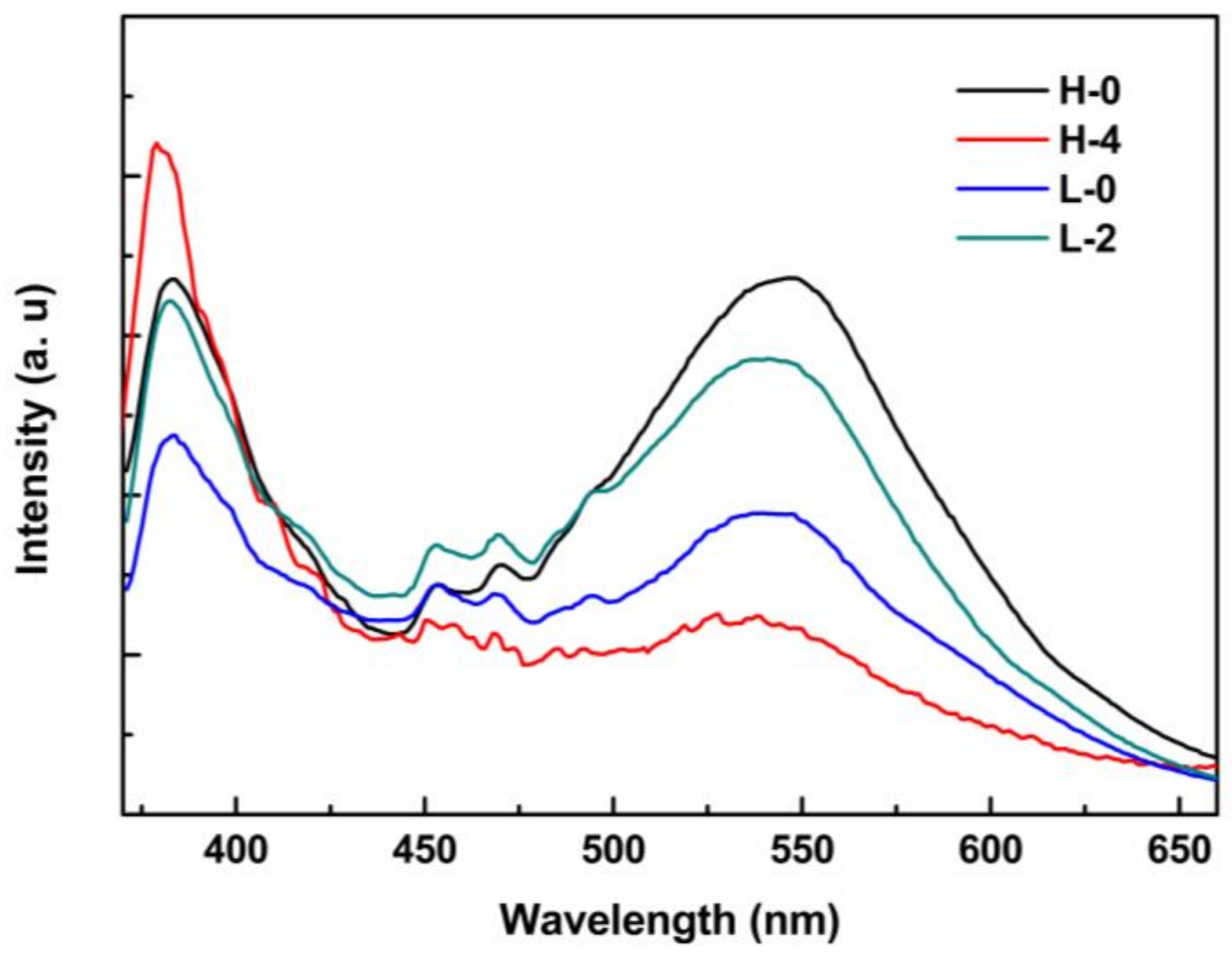
Figure 6 shows the room-temperature PL spectra of the sample H-0, H-4, L-0, and L-2. All the samples exhibit a UV emission peak located at around 384 nm, which is attributed to the recombination of the free excitons (electrons from the conduction band and holes from the valence band) [34,35,36]. The sample H-4 shows a strong and sharp UV emission indicating its high crystalline. The green emissions are found ranging from 500 nm to 600 nm which are mainly attributed to the defects, such as O-vacancy, Zn-interstitial, and absorbed molecules [30,31,37]. O-vacancy has three different charged states: neutralized oxygen vacancy (), single-ionized oxygen vacancy (), and doubly-ionized vacancy (). The electrons from the conduction band (CB) recombine with the doubly-ionized vacancies (), which generate green emission. The single-ionized oxygen vacancies () capture electrons from CB, and then recombine with the photo-generated holes in the valance band (VB), which always generates a green emission. It is commonly believed that the oxygen-related species, such as O2 and OH− can be absorbed on the surface of ZnO nanorods. The electrons or holes captured by the O2 and OH− on the surface of ZnO nanorods can nonradiatively recombine [37]. The large surface-to-volume ratio will induce a high amount of O2 and OH− absorbed on the surface, which can capture more photo-generated electrons or holes. Nonradiative recombinations increase and, as a result, induce the decrease of green emissions. For our samples, H-4 with ultrasharp tips has the highest surface-to-volume ratio and, accordingly has the lowest green emission. The sample H-0, with the lowest surface-to-volume ratio, exhibits the highest green emission. L-0 and L-2 are in the middle levels.
4. Conclusions
In conclusion, the precursor concentration and the growth time in each step are the key factors to determine the morphology of the ZnO nanorods. By changing the growth conditions, ZnO nanorods with different morphologies, including flat top, cone top, syringe-shaped, and nail-shaped, were obtained. The growth mechanism of each nanostructure was discussed. The room-temperature PL spectra show that the syringe-shaped ZNAs with ultra-sharp tips have higher intensity of UV emission peak, indicating their high crystalline quality.
Acknowledgments
The work was financially supported by The Provincial Natural Science Foundation of Guangdong Province, China (no. 2017A030310064), and The National Natural Science Foundation of China (no. 61307080, no. 61404052, no. 51372092, no. 51672090).
Author Contributions
Guannan He characterized the samples, analyzed the data and wrote the article. Zhenxuan Lin performed the experiments and obtained ZnO nanorod arrays with different structures. Bo Huang and Weifeng Yang contributed in the discussion of the experimental results and proposed growth models. Qinyu He and Lunxiong Li contributed in the revision of the paper.
Conflicts of Interest
The authors declare no conflict of interest.
References
- Choi, S.; Bonyani, B.; Sun, G.J.; Lee, J.K.; Hyun, S.K.; Lee, C. Cr2O3 nanoparticle-functionalized WO3 nanorods for ethanol gas sensors. Appl. Surf. Sci. 2018, 432, 241–249. [Google Scholar] [CrossRef]
- Long, H.W.; Li, Y.Q.; Zeng, W. Substrate-free synthesis of WO3 nanorod arrays and their superb NH3-sensing performance. Mater. Lett. 2017, 209, 342–344. [Google Scholar] [CrossRef]
- Yin, Z.Z.; Cheng, S.W.; Xu, L.B.; Liu, H.Y.; Huang, K.; Li, L.; Zhai, Y.Y.; Zeng, Y.B.; Liu, H.Q.; Shao, Y.; et al. Highly sensitive and selective sensor for sunset yellow based on molecularly imprinted polydopmine-coated multi-walled carbon nanotubes. Biosens. Bioelectron. 2018, 100, 565–570. [Google Scholar] [CrossRef] [PubMed]
- Wang, Z.H.; Yang, C.C.; Yu, H.C.; Yeh, H.T.; Peng, Y.M.; Su, Y.K. Electron field emission enhancement based on Al-doped ZnO nanorod arrays with UV exposure. IEEE Trans. Electron Devices 2018, 65, 251–256. [Google Scholar] [CrossRef]
- Hou, J.W.; Wang, B.B.; Ding, Z.J.; Dai, R.C.; Wang, Z.P.; Zhang, Z.M.; Zhang, J.W. Facile fabrication of infrared photodetector using metastable vanadium dioxide VO2 (B) nanorod networks. Appl. Phys. Lett. 2017, 111, 072107. [Google Scholar] [CrossRef]
- Lee, S.; Lee, W.Y.; Jang, B.; Kim, T.; Bae, J.H.; Cho, K.; Kim, S.; Jang, J. Sol-gel processed p-type CuO phototransistor for a near-infrared sensor. IEEE Electron Device Lett. 2018, 39, 47–50. [Google Scholar] [CrossRef]
- Li, Y.M.; Zhang, Q.S.; Niu, L.Y.; Liu, J.; Zhou, X.F. TiO2 nanorod arrays modified with SnO2-Sb2O3 nanoparticles and application in perovskite solar cell. Thin Solid Films 2017, 621, 6–11. [Google Scholar] [CrossRef]
- Momeni, M.M.; Ghayeb, Y.; Menati, M. Facile and green synthesis of CuO nanoneedles with high photo catalytic activity. J. Mater. Sci. Mater. Electron. 2016, 27, 9454–9460. [Google Scholar] [CrossRef]
- Özgür, Ü.; Alivov, Y.I.; Liu, C.; Teke, A.; Reshchikov, M.A.; Doğan, S.; Avrutin, V.; Cho, S.-J.; Morkoç, H. A comprehensive review of ZnO materials and devices. J. Appl. Phys. 2005, 98, 041301. [Google Scholar] [CrossRef]
- Montenegro, D.N.; Souissi, A.; Martinez-Tomas, C.; Munoz-Sanjose, V.; Sallet, V. Morphology transtions in ZnO nanorods grown by MOCVD. J. Cryst. Growth 2012, 359, 122–128. [Google Scholar] [CrossRef]
- Lu, S.N.; Qi, J.J.; Wang, Z.Z.; Lin, P.; Liu, S.; Zhang, Y. Size effect in a cantilevered ZnO micro/nanowire and its potential as a performance tunable force sensor. RSC Adv. 2013, 3, 19375–19379. [Google Scholar] [CrossRef]
- Yuan, Z.L.; Yao, J.C. Growth of well-aligned ZnO nanorod arrays and their application for photovoltaic devices. J. Electron. Mater. 2017, 46, 6461–6465. [Google Scholar] [CrossRef]
- Lung, C.M.; Wang, W.C.; Chen, C.H.; Chen, L.Y.; Chen, M.J. ZnO/Al2O3 core/shell nanorods array as excellent anti-reflection layers on silicon solar cells. Mater. Chem. Phys. 2016, 180, 195–202. [Google Scholar] [CrossRef]
- Fujiwara, H.; Suzuki, T.; Niyuki, R.; Sasaki, K. ZnO nanorod array random lasers fabricated by a laser-induced hydrothermal synthesis. New J. Phys. 2016, 18, 103046. [Google Scholar] [CrossRef]
- Harale, N.S.; Kamble, A.S.; Tarwal, N.L.; Mulla, I.S.; Rao, V.K.; Kim, J.H.; Patil, P.S. Hydrothermally grown ZnO nanorods arrays for selective NO2 gas sensing: Effect of anion generating agents. Ceram. Int. 2016, 42, 12807–12814. [Google Scholar] [CrossRef]
- Kim, D.; Kim, W.; Jeon, S.; Yong, K. Highly efficient UV-sensing properties of Sb-doped ZnO nanorod arrays synthesized by a facile, singlestep hydrothermal reaction. RSC Adv. 2017, 7, 40539–40548. [Google Scholar] [CrossRef]
- Husham, M.; Hamidon, N.M.; Paiman, S.; Abuelsamen, A.A.; Farhat, O.F.; Al-Dulaimi, A.A. Synthesis of ZnO nanorods by microwave-assisted chemical-bath deposition for highly sensitive self-powered UV detection application. Sens. Actuators A-Phys. 2017, 263, 166–173. [Google Scholar] [CrossRef]
- Han, C.; Chen, Z.; Zhang, N.; Colmenares, J.C.; Xu, Y.J. Hierarchically CdS decorated 1D ZnO nanorods-2D graphene hybrids: Low temperature synthesis and enhanced photocatalytic performance. Adv. Funct. Mater. 2015, 25, 221–229. [Google Scholar] [CrossRef]
- Zhang, N.; Xie, S.J.; Wenig, B.; Xu, Y.J. Vertically aligned ZnO-Au@CdS core-shell nanorod arrays as an all-solid-state vectorial Z-scheme system for photocatalytic application. J. Mater. Chem. A 2016, 4, 18804–18814. [Google Scholar] [CrossRef]
- Liu, S.Q.; Tang, Z.R.; Sun, Y.G.; Colmenares, J.C.; Xu, Y.J. One-dimension-based spatially ordered architectures for solar energy conversion. Chem. Soc. Rev. 2015, 44, 5053–5075. [Google Scholar] [CrossRef] [PubMed]
- Wu, C.C.; Wuu, D.S.; Lin, P.R.; Chen, T.N.; Horng, R.H. Realization and manipulation of ZnO nanorod arrays on sapphire substrates using a catalyst-free metalorganic chemical vapor deposition technique. J. Nanosci. Nanotechnol. 2010, 10, 3001–3011. [Google Scholar] [CrossRef] [PubMed]
- Wu, C.C.; Wuu, D.S.; Lin, P.R.; Chen, T.N.; Horng, R.H. Three-step growth of well-aligned ZnO nanotube arrays by self-catalyzed metalorganic chemical vapor deposition method. Cryst. Growth Des. 2009, 9, 4555–4561. [Google Scholar] [CrossRef]
- Kawakami, M.; Hartanto, A.B.; Nakata, Y.; Okada, T. Synthesis of ZnO nanorods by nanoparticle assisted pulsed-laser deposition. Jpn. J. Appl. Phys. 2003, 42, L33–L35. [Google Scholar] [CrossRef]
- Kim, M.S.; Nam, G.; Leem, J.Y. Photoluminescence studies of ZnO nanorods grown by plasma-assisted molecular beam epitaxy. J. Nanosci. Nanotechnol. 2013, 13, 3582–3585. [Google Scholar] [CrossRef] [PubMed]
- Chen, Z.T.; Gao, L. A facile route to ZnO nanorod arrays using wet chemical method. J. Cryst. Growth 2006, 293, 522–527. [Google Scholar] [CrossRef]
- Sardana, S.K.; Chandrasekhar, P.S.; Kumar, R.; Komarala, V.K. Efficiency enhancement of silicon solar cells with vertically aligned ZnO nanorod arrays as an antireflective layer. Jpn. J. Appl. Phys. 2017, 56, 040305. [Google Scholar] [CrossRef]
- Ahsanylhaq, Q.; Umar, A.; Hahn, Y.B. Growth of aligned ZnO nanorods and nanopencils on ZnO/Si in aqueous solution: Growth mechanism and structural and optical properties. Nanotechnology 2007, 18, 115603. [Google Scholar] [CrossRef]
- Xu, S.; Lao, C.S.; Weintraub, B.; Wang, Z.L. Density-controlled growth of aligned ZnO nanowire arrays by seedless chemical approach on smooth surfaces. J. Mater. Res. 2008, 23, 2072–2077. [Google Scholar] [CrossRef]
- Wang, Z.; Qian, X.F.; Yin, J.; Zhu, Z.K. Aqueous solution fabrication of large-scale arrayed obelisk-like zinc oxide nanorods with high efficiency. J. Solid State Chem. 2004, 177, 2144–2149. [Google Scholar] [CrossRef]
- Prabhu, M.; Mayandi, J.; Mariammal, R.N.; Vishnukanthan, V.; Pearce, J.M.; Soundararajan, N.; Ramachandran, K. Peanut shaped ZnO microstructures: Controlled synthesis and nucleation growth toward low-cost dye sensitized solar cells. Mater. Res. Express 2015, 2, 066202. [Google Scholar] [CrossRef]
- Jang, J.M.; Kim, S.D.; Kim, S.D.; Choi, H.M.; Kim, J.Y.; Jung, W.G. Morphology change of self-assembled ZnO 3D nanostructures with different pH in the simple hydrothermal process. Mater. Chem. Phys. 2009, 113, 389–394. [Google Scholar] [CrossRef]
- Wilson, S.J.; Hutley, M.C. The optical properties of ‘moth eye’ antireflection surfaces. Opt. Acta 1982, 29, 993–1009. [Google Scholar] [CrossRef]
- Zhang, D.B.; Wang, S.J.; Cheng, K.; Dai, S.X.; Hu, B.B.; Han, X.; Shi, Q.; Du, Z.L. Controllable fabrication of patterned ZnO nanorod arrays: Investigations into the impacts on their morphology. ACS Appl. Mater. Interfaces 2012, 4, 2969–2977. [Google Scholar] [CrossRef] [PubMed]
- Yue, S.S.; Lu, J.J.; Zhang, J.Y. Controlled growth of well-aligned hierarchical ZnO arrays by a wet chemical method. Mater. Lett. 2009, 63, 2149–2152. [Google Scholar] [CrossRef]
- Bai, S.L.; Guo, T.; Zhao, Y.B.; Luo, R.X.; Li, D.Q.; Chen, A.F.; Liu, C.C. Mechanism enhancing gas sensing and first-principle calculations of Al-doped ZnO nanostructures. J. Mater. Chem. A 2013, 1, 11335–11342. [Google Scholar] [CrossRef]
- Wang, M.J.; Shen, Z.R.; Chen, Y.L.; Zhang, Y.; Ji, H.M. Atomic structure-dominated enhancement of acetone sensing for a ZnO nanoplate with highly exposed (0001) facet. CrystEngComm 2017, 19, 6711–6718. [Google Scholar] [CrossRef]
- Xu, J.P.; Shi, S.B.; Wang, C.; Zhang, Y.Z.; Liu, Z.M.; Zhang, X.G.; Li, L. Effect of surface-to-volume ratio on the optical and magnetic properties of ZnO nanorods by hydrothermal method. J. Alloys Compd. 2015, 648, 521–526. [Google Scholar] [CrossRef]
Figure 1.
The cross-section and top view (inset) images of the ZNAs synthesized with 0.05 M precursor concentration in T1 for 2 h and 0.01 M in T2 for: (a) 0 h (H-0); (b) 1 h (H-1); (c) 2 h (H-2); (d) 4 h (H-4); and (e) the cross-section and (f) the top view images of the ZNAs synthesized with 0.05 M precursor concentration in T1 for 2 h and 0.01 M in T2 for 10 h (H-10). The insets are their high-magnification images.
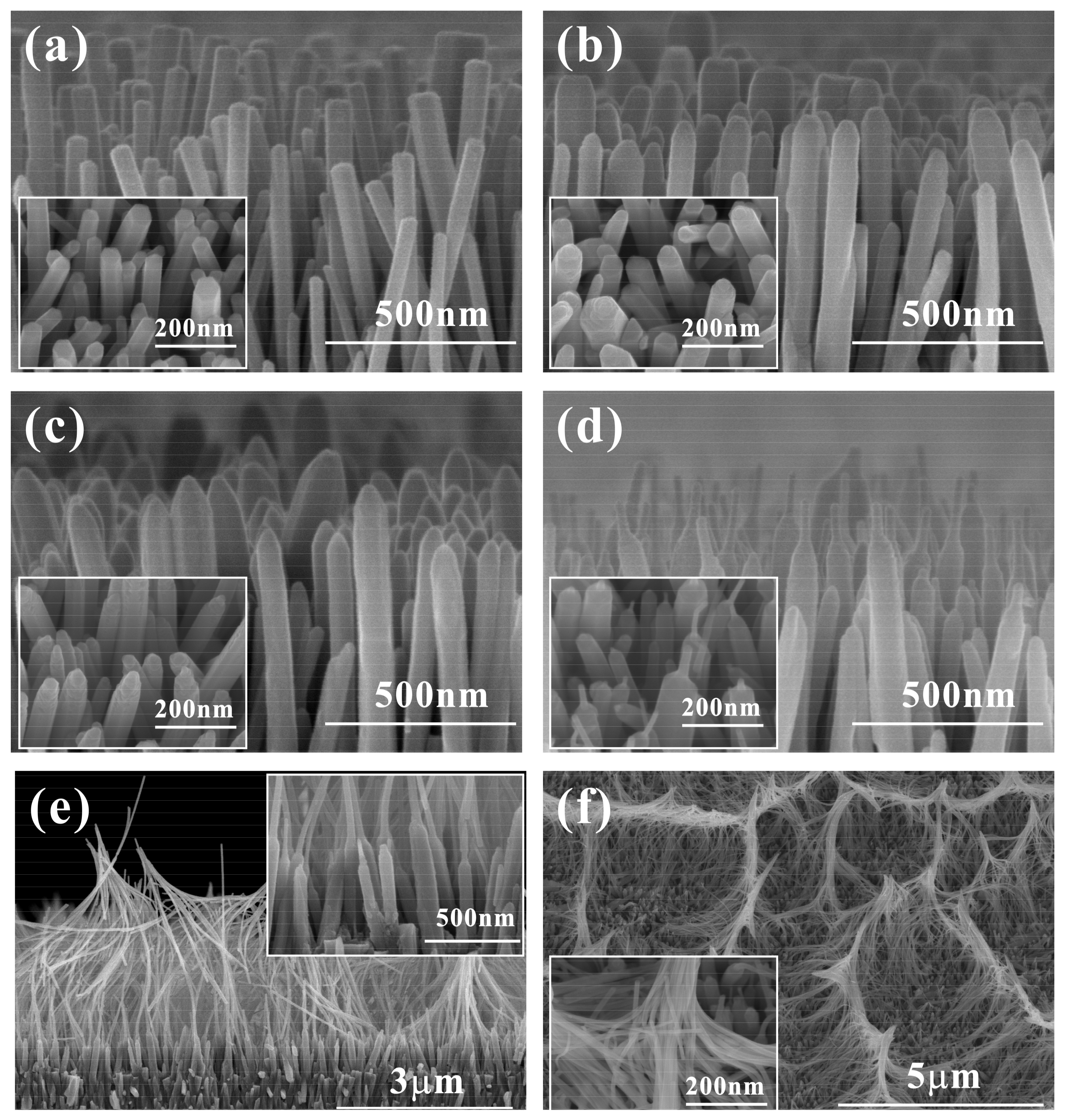
Figure 2.
(a,b) The top-view and cross-section SEM images of the sample L-0 which was synthesized with 0.01 M precursor concentration in T1 for 2 h without T2 treatment. (c,d) The top view and cross-section SEM images of the sample L-2 which was synthesized with 0.01 M precursor concentration in T1 for 2 h, and with 0.05 M precursor concentration in T2 for 2 h.

Figure 3.
The XRD patterns of the seed layer and the sample L-0, L-2, H-0, and H-4.
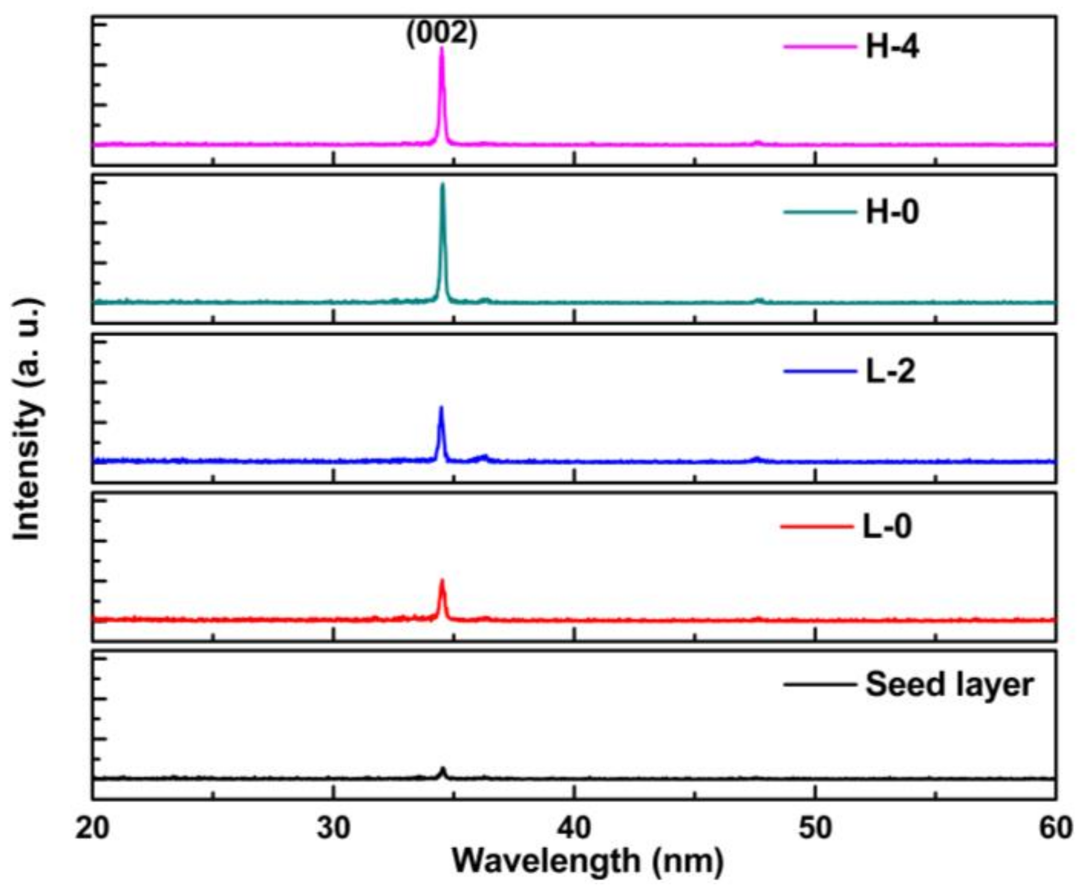
Figure 4.
(a,b) The TEM images of the syringe-shaped ZNAs of the sample H-4. (c,d) HRTEM images of the selected areas marked on the syringe-shaped ZnO nanorod shown in (b). Inset of (d) is the corresponding SAED pattern.
Figure 4.
(a,b) The TEM images of the syringe-shaped ZNAs of the sample H-4. (c,d) HRTEM images of the selected areas marked on the syringe-shaped ZnO nanorod shown in (b). Inset of (d) is the corresponding SAED pattern.
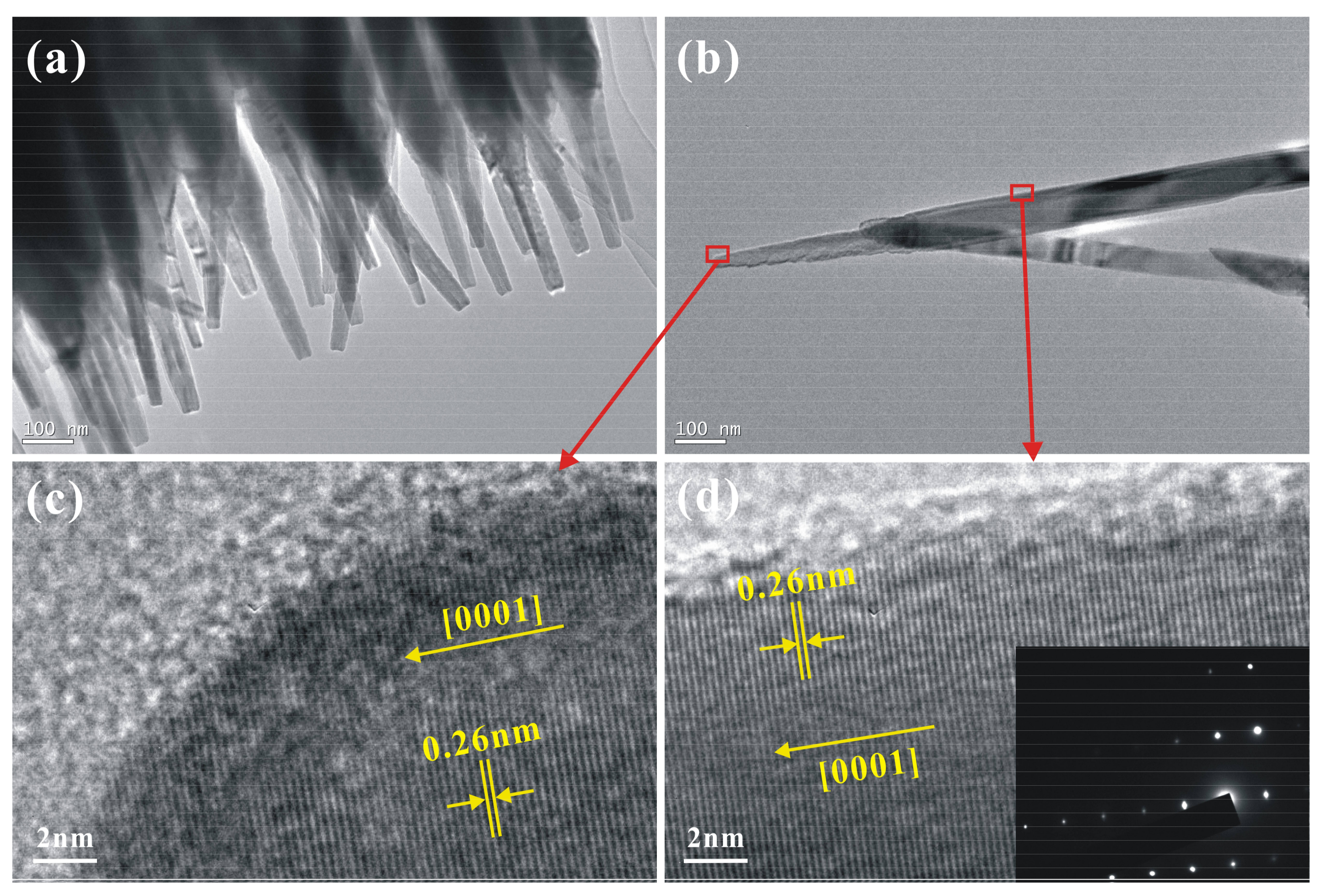
Figure 5.
Schematic of the growth mechanisms of: (a) the syringe-shaped ZNAs; and (b) the nail-shaped ZNAs.
Figure 5.
Schematic of the growth mechanisms of: (a) the syringe-shaped ZNAs; and (b) the nail-shaped ZNAs.
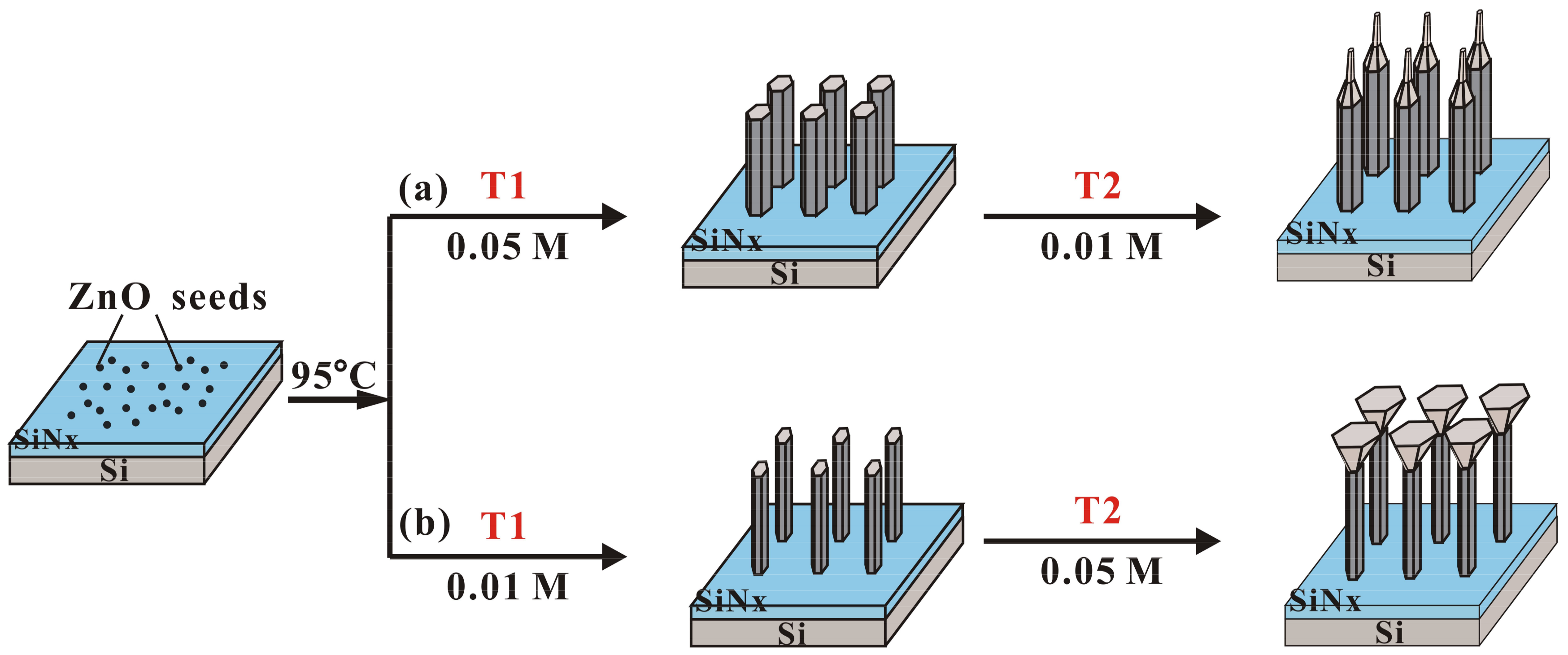
Figure 6.
Room-temperature PL spectra of the sample H-0, H-4, L-0, and L-2.


Table 1.
Growth conditions of the ZNAs.
| Sample | Growth Temperature (°C) | T1 | T2 | ||
|---|---|---|---|---|---|
| Precursor Concentration (M) | Growth Time (h) | Precursor Concentration (M) | Growth Time (h) | ||
| H-0 | 95 | 0.05 | 2 | ---- | ---- |
| H-1 | 0.01 | 1 | |||
| H-2 | 2 | ||||
| H-4 | 4 | ||||
| H-10 | 10 | ||||
| L-0 | 0.01 | ---- | ---- | ||
| L-2 | 0.05 | 2 | |||
© 2018 by the authors. Licensee MDPI, Basel, Switzerland. This article is an open access article distributed under the terms and conditions of the Creative Commons Attribution (CC BY) license (http://creativecommons.org/licenses/by/4.0/).
Share and Cite
MDPI and ACS Style
He, G.; Huang, B.; Lin, Z.; Yang, W.; He, Q.; Li, L. Morphology Transition of ZnO Nanorod Arrays Synthesized by a Two-Step Aqueous Solution Method. Crystals 2018, 8, 152. https://doi.org/10.3390/cryst8040152
AMA Style
He G, Huang B, Lin Z, Yang W, He Q, Li L. Morphology Transition of ZnO Nanorod Arrays Synthesized by a Two-Step Aqueous Solution Method. Crystals. 2018; 8(4):152. https://doi.org/10.3390/cryst8040152
Chicago/Turabian StyleHe, Guannan, Bo Huang, Zhenxuan Lin, Weifeng Yang, Qinyu He, and Lunxiong Li. 2018. "Morphology Transition of ZnO Nanorod Arrays Synthesized by a Two-Step Aqueous Solution Method" Crystals 8, no. 4: 152. https://doi.org/10.3390/cryst8040152
Note that from the first issue of 2016, this journal uses article numbers instead of page numbers. See further details here.