An Analytical Solution to Lumped Parameter Equivalent Circuit Model of Organic Solar Cells


College of Information Science and Engineering, Huaqiao University, Xiamen 361021, China
*
Author to whom correspondence should be addressed.
†
These two authors contributed equally to this work.
Crystals 2018, 8(5), 224; https://doi.org/10.3390/cryst8050224
Submission received: 21 April 2018
/
Revised: 6 May 2018
/
Accepted: 17 May 2018
/
Published: 18 May 2018
(This article belongs to the Special Issue Selected Papers from Taiwan Association for Academic Innovation, TAAI 2018)
Abstract
:In this paper, an analytical and closed-form solution to the lumped parameter equivalent circuit model of organic solar cells is proposed to complete the simulations of the S-shaped I-V characteristics. Based on the model previously proposed by Mazhari, the set of terminal current and voltage equations describing the three diodes is solved and the effects from the model parameters are illustrated. Our solutions are verified by being compared with the least square method results and experimental data, respectively. Good agreements show that our solution calculation scheme is not only both accurate and efficient, but also valid in the whole operation regime of solar cells, especially for the S-shaped kink on the condition where the terminal voltage is larger than the open circuit voltage. Such an analytical solution can play an important role in the simulations for I-V characteristics of solar cells, fast extractions of the model parameters, and implements into practical photovoltaic device simulators.
1. Introduction
Compared with the conventional silicon-based solar cells, organic solar cells (OSCs) [1,2], as promising candidates for next generation solar cells [3,4,5,6], show many advantages in intensive researches, such as low temperature preparation [2], flexibility [7], and so on. However, as the important physical phenomena, S-shaped kink exhibits in I-V characteristics of OSCs, especially for the polymer OSCs [7,8,9]. The S-shaped kink unquestionably impairs energy conversion capacity [10,11] and probably origins from the interface phenomena [12,13,14] including charge accumulation at the cathode interface, presence of strong interface dipoles, unbalanced charge transport, and interfacial energy barriers, etc. Therefore, to electrically explain the S-shaped I-V characteristics of OSCs, the lumped parameter equivalent circuit model considering the S-shaped kink is necessary for further developments and researches of OSCs.
Compared with the conventional solar cell lumped-parameter models [15,16] including single diode cannot describe the above-mentioned S-shaped I-V characteristics observed in OSCs. On the basis of the conventional model, some multiple-diode lumped-parameter equivalent circuit models [17,18,19,20,21] are proposed to reproduce the S-shaped I-V characteristics of OSCs. In these models [17,18,19,20,21], an additional series sub-circuit is added into the conventional model, in order to create the S-shaped kink in the first quadrant. To date, compared with the above models [17,18,19,20,21], Mazhari’s model [22] is the simplest lumped parameter equivalent model with the ability of electronically explaining the S-shaped kink. As a typical three-diode lumped parameter model, it only includes seven parameters used for simulations. It is noted that, to the best of our knowledge, the analytical solutions are not feasible except for some special results of parameters [18,22]. Therefore, an analytical solution of Mazhari’s model [22] is required to overcome the limitation for analyzing and simulating the S-shaped I-V characteristics of OSCs.
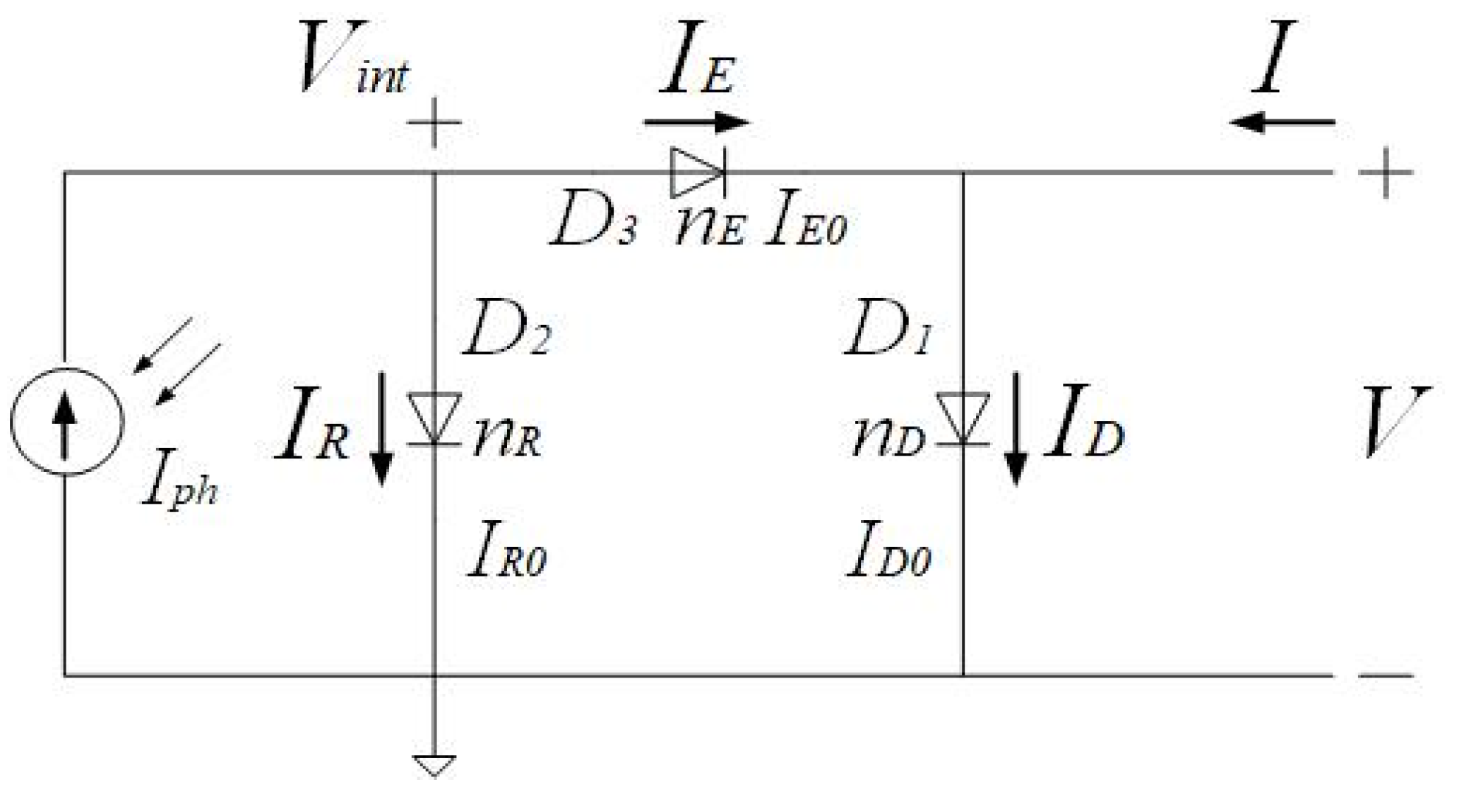
In this paper, we propose a general method to derive the analytical closed-form solution of Mazhari’s model [22] as shown in Figure 1 without depending on the least square method and the approximate method, which are prone to consume large amounts of computation time and conceal physical meaning, respectively. First of all, we express the terminal current as a function of the terminal voltage in OSCs. Subsequently, we derive the solution of Mazhari’s model [22] based on the Newton–Raphson root-finding scheme leading to fast convergence. Then, we verify our solutions by using the least square method results and experimental data, respectively. Finally, we discuss the influences of the model parameters. The usefulness of our solution is speeding up the simulation of Mazhari’s model, facilitating the extraction of model parameters, and studying the S-shaped I-V characteristics of OSCs.
2. Model’s Equation Solution
In Figure 1, the basic schematic diagram of the lumped-parameter equivalent circuit model proposed by Mazhari consists of three diodes and a photo-generated current source without any series or shunt resistances. The diode D1 simulates the I-V characteristics of OSCs on the dark condition, the diode D2 simulates the loss of polarons resulting from recombination, and the diode D3 simulates the extraction of free carriers after the dissociation of polarons. Therefore, the above three diodes account for dark, recombination, and extraction currents, i.e., ID, IR, and IE, respectively. In addition, Iph is a constant photo-generated current. In fact, the constant current source Iph and the recombination IR are combined in parallel to represent the non-constant photo-generated current. According to Kirchhoff’s current law at two earth-free nodes in Figure 1, we can obtain Equations (1) and (2) as
Substituting Shockley’s ideal diode current equation and Equation (1) into Equation (2), we can obtain the terminal current and voltage relation function [23] as
Here, ID0, IR0, and IE0 are the reverse saturation currents of diodes D1, D2, and D3, respectively. nD, nR, and nE are the ideality factors of three diodes representing the divergence from the ideal diode. Vt is the thermal voltage symbolled by kT/q, where k is the Boltzmann constant, T is the absolute temperature, and q is the electron charge.
In order to compactly implement Mazhari’s model into photovoltaic device simulators and complete the computer-aided-design, we expect finding both an accurate and efficient solution, i.e., an explicit solution, of Equation (3) describing the terminal current and voltage relationship in Mazhari’s model. Unfortunately, Equation (3) cannot be solved directly except for some special cases [23]. Obviously, the explicit solutions in these special cases addressed in [23] cannot roundly demonstrate the S-shaped I-V characteristics of OSCs. In addition, the least square method processes enough accuracy, but consumes a lot of computing time to complete simulations. In fact, a trade-off between accuracy and efficiency is a key of implementing Mazhari’s model solution compactly into computer-aided photovoltaic device simulations. In this paper, based on the Newton–Raphson root-finding scheme, we solve the terminal voltage V as a function of the terminal current I. It is interesting that the Newton–Raphson root-finding scheme makes V come into fast convergence under the relative error of 1‰. In addition, the fitting parameters used in simulations can be acquired by the systematic parameter extraction procedure proposed in [22].
3. Verification and Discussion
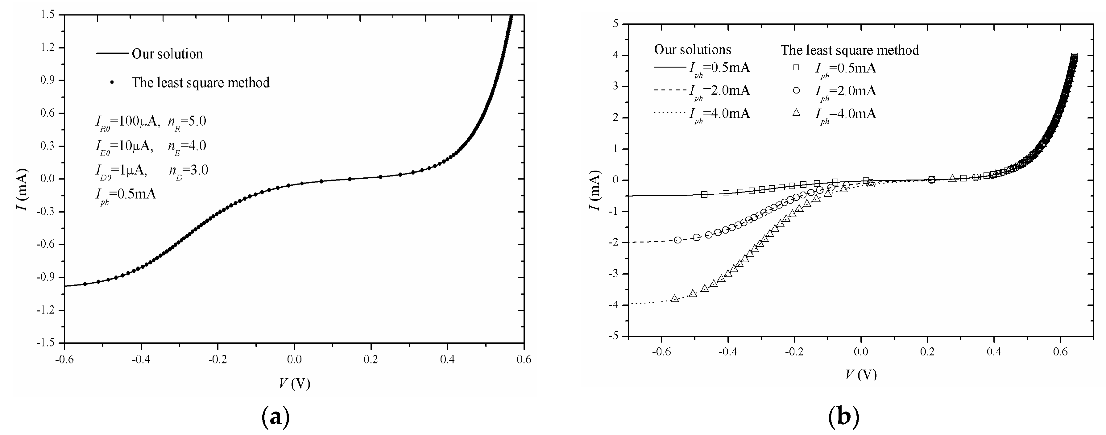
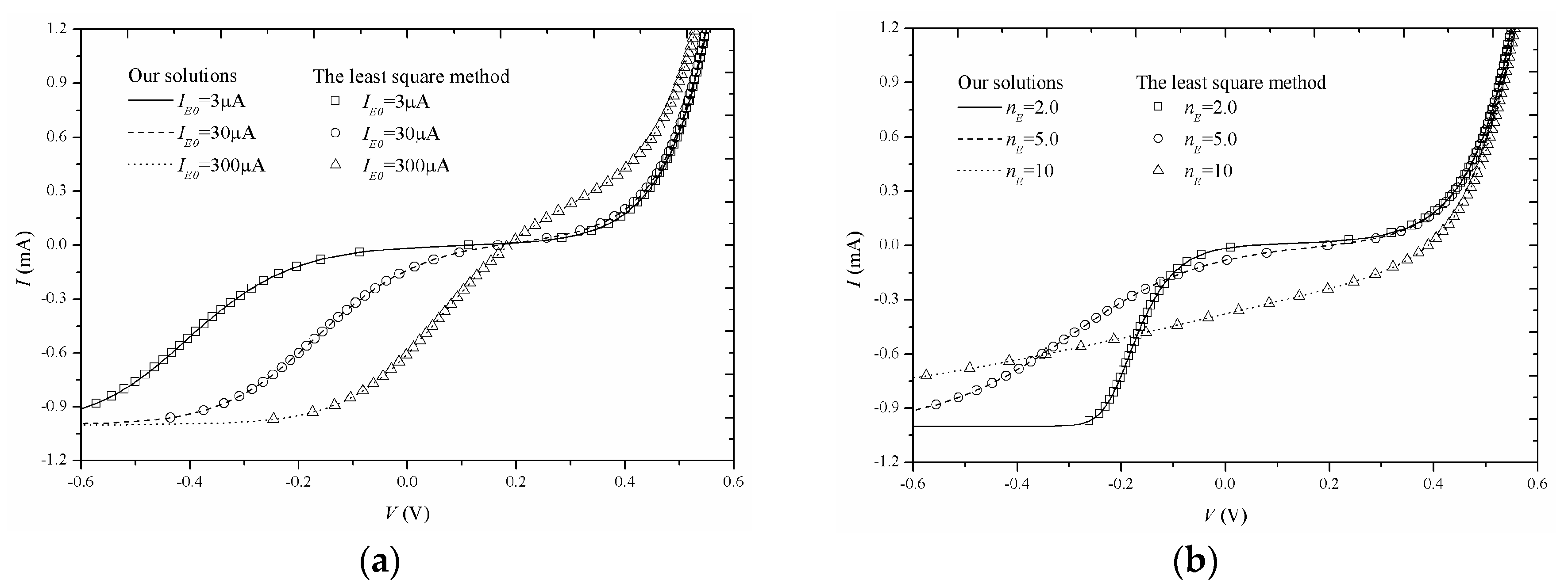
Firstly, based on both the Newton–Raphson root-finding scheme and the least square method, we solve Mazhari’s lumped-parameter equivalent circuit model of solar cells shown in Figure 1, respectively. Good agreements between our solutions and the least square method results shown in Figure 2, Figure 3, Figure 4 and Figure 5 demonstrate that our solutions can be adopted to simulate the S-shaped I-V characteristics of OSCs in the different cases.
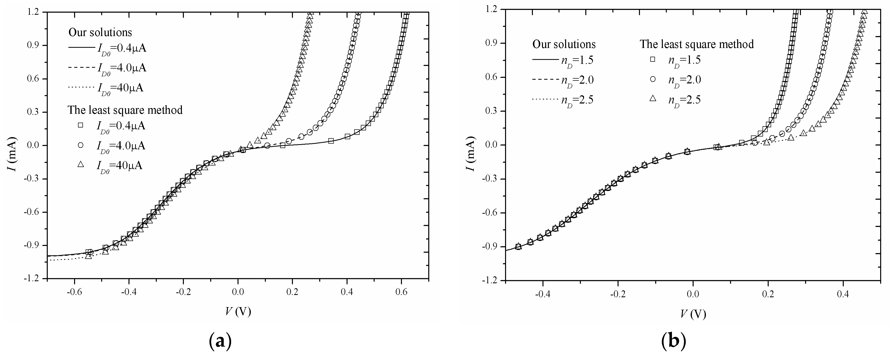
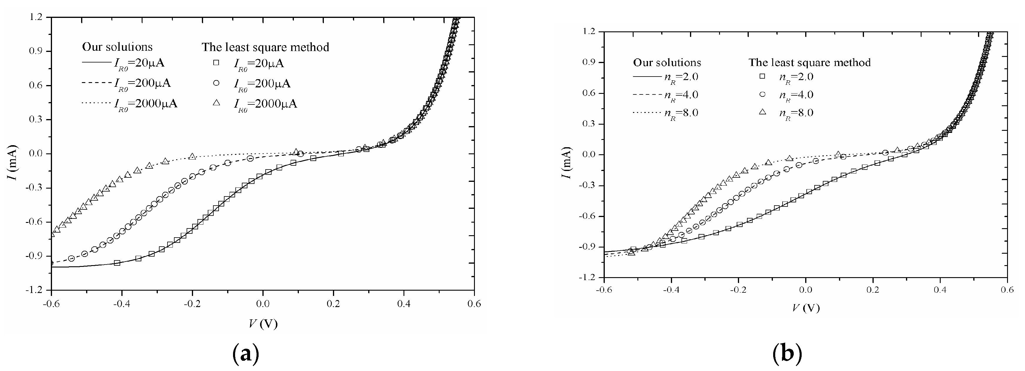
Secondly, we discuss the effects from Mazhari’s model parameters on OSC I-V characteristics. In Figure 2, we can observe that the constant photo-generated current Iph can only influence the OSC I-V characteristics in the third quadrant but not that in the first quadrant. In other words, S-shaped kink does not depend on Iph. Figure 3 shows that the OSC S-shaped kink depends on the parameters ID0 and nD of the first diode D1. It is noted that ID0 determines the quantity of the terminal voltage V in Figure 3a and nD determines the slope of the S-shaped kink in Figure 3b. Similarly, we can observe the influence from the Diode D2 on the I-V characteristics in the third quadrant from Figure 4. IR0 and nR can affect the quantity of the terminal voltage V and the slope of I-V characteristics, respectively. The role of the Diode D3 is shown in Figure 5. It is noted that both D3 and D1 describe the exponential-like rise of the S-shaped kink, but D3 can control fine tuning for the S-shaped kink.
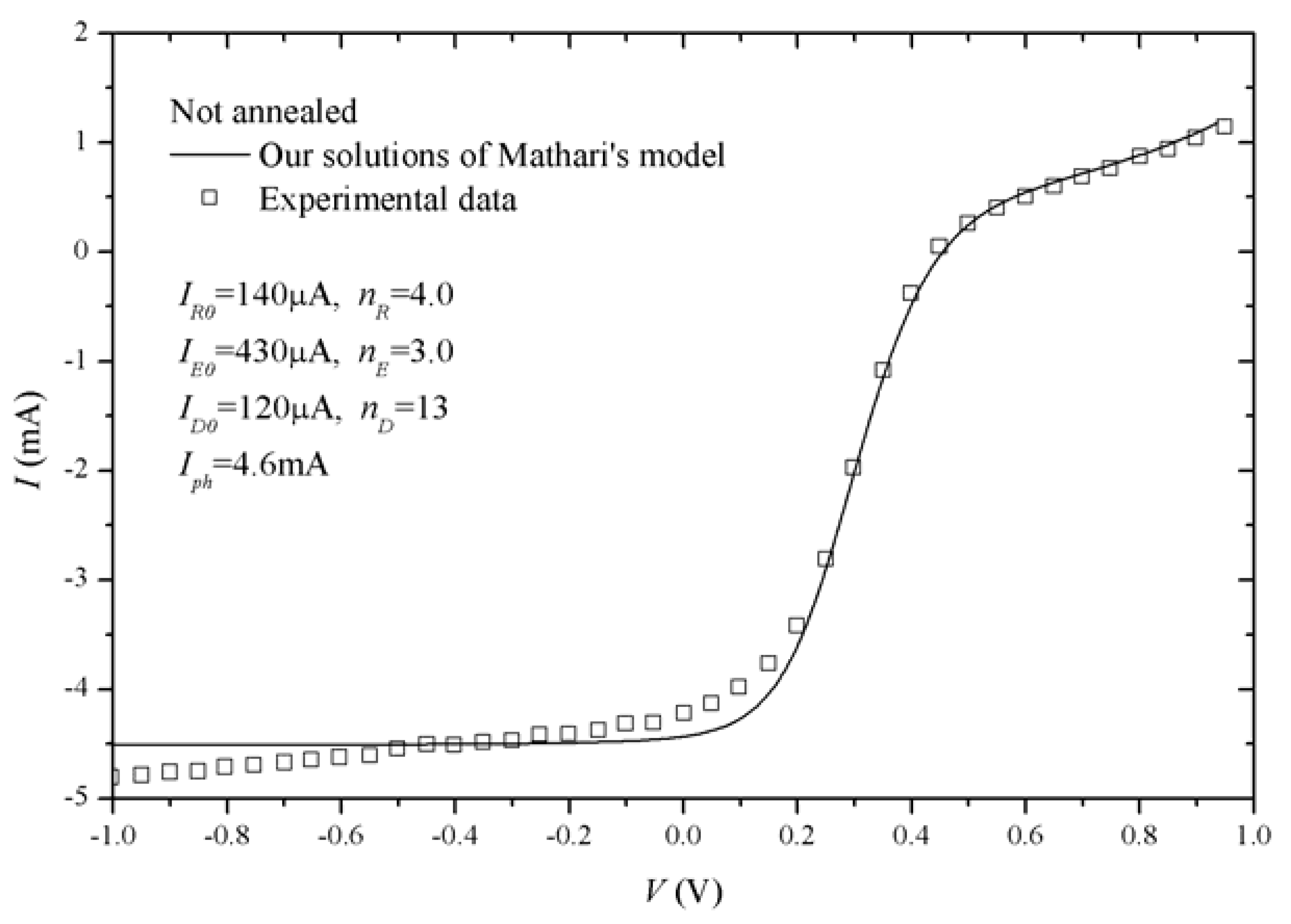
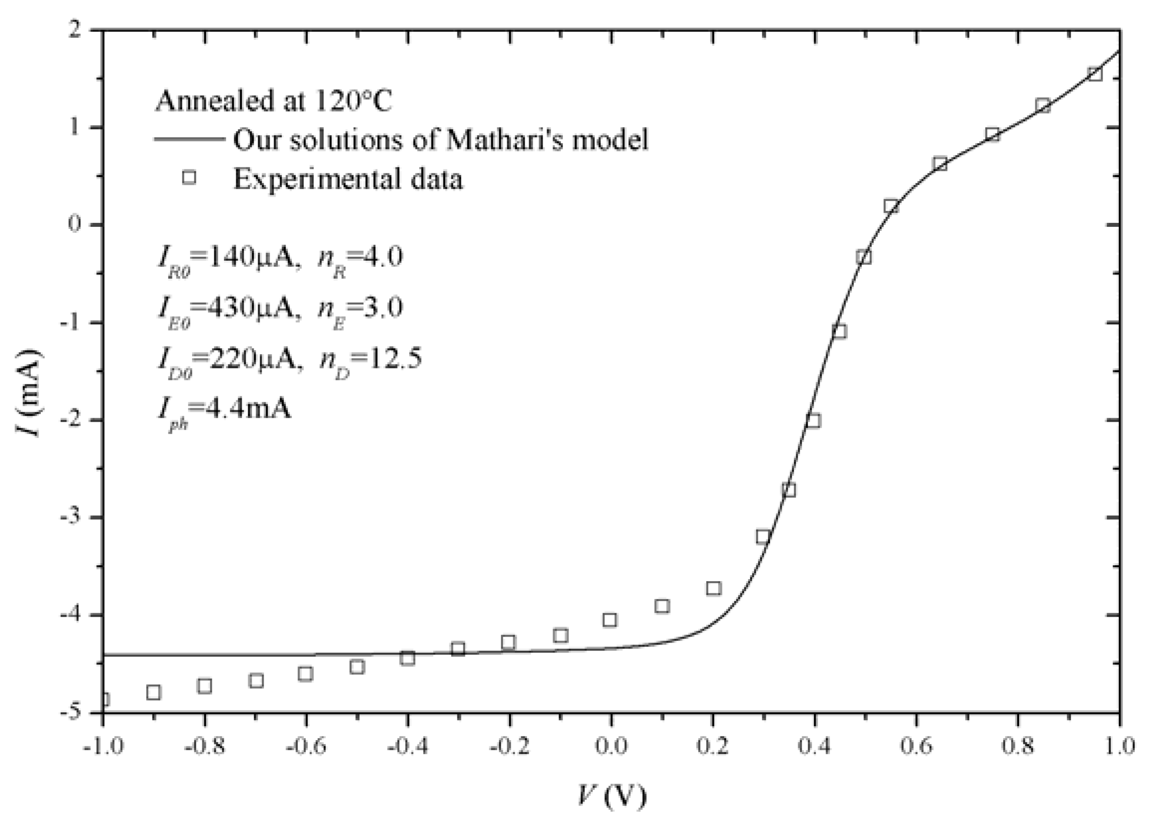
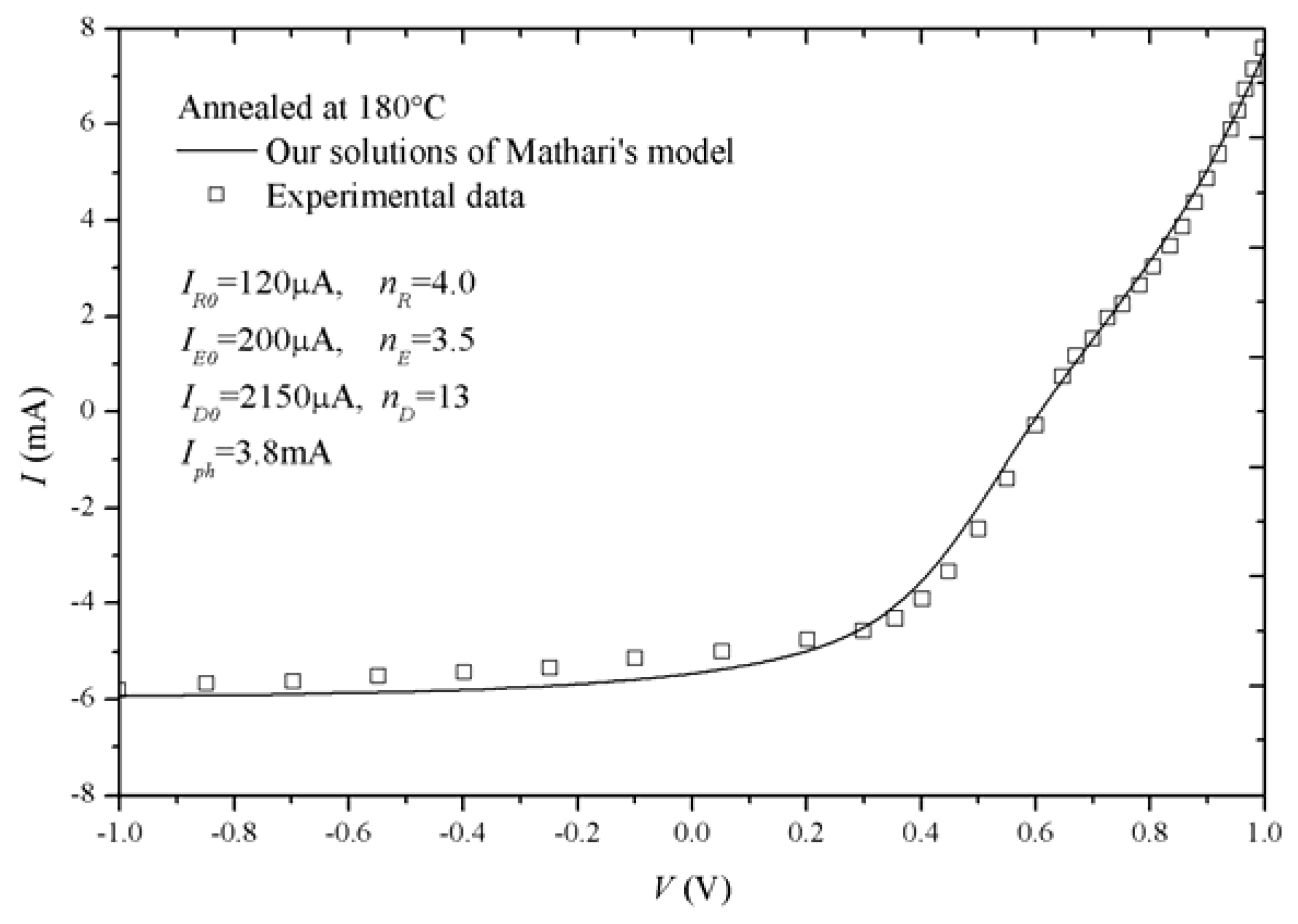
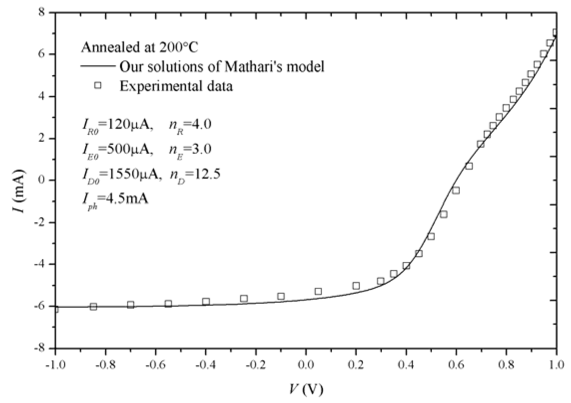
Thirdly, in order to practically validate our solutions of Mazhari’s model, we compare our solutions with experimental data [20], as shown in Figure 6, Figure 7, Figure 8, Figure 9 and Figure 10. In [20], the solar cell devices were an enhanced bilayer of the fullerene C60 and the purified Poly[2-methoxy-5-(2-ethylhexyloxy)-1,4-phenylene-vinylene], which act as electron acceptor and donor, respectively. Films are prepared on clean ITO glass, which is coated with 50 nm of PEDOT:PSS and subsequently coated with 50 nm of Al to serve as the cathode. I-V curves were measured in an N2 atmosphere with devices exposed to 1000 W/m2 simulated AM1.5G sunlight. It is noted that thermal annealing at different temperatures can be used to reduce the S-shape of OSC I-V characteristics and increase power-conversion efficiency. For the different annealing temperatures, our solutions of Mazhari’s model can also give the rational explanation of the S-shaped I-V characteristics of OSCs. Especially for the S-shaped kink in the first quadrant, we can observe that our solutions can give accurate predictions. The annealing temperature is higher and the S-shaped I-V curves are better suppressed in the first and third quadrants. It is noted that I-V curves show a linear-like relationship, especially in the third paragraph, when the annealing temperature is less than 150 °C. However, there are not linear items in Equation (3) except two constant −Iph and −IR0. Therefore, large errors are introduced from Mazhari’s model in the third quadrant. As the annealing temperature increases to more than 150 °C, the S-shaped I-V curves are suppressed so that the slopes of I-V curves in the third quadrant approach zero. In this case, the constants −Iph and −IR0 in (3) play an important role to make sure Mazhari’s model has an accurate fitting with experimental data.
4. Conclusions
In this paper, based on the Newton–Raphson root-finding scheme, we derive the closed-form solution of Mazhari’s lumped-parameter equivalent circuit model of organic solar cells (OSCs). The process of calculating our solution has high accuracy and fast convergences. Subsequently, we adopt the least square method to verify our solutions and discuss the effects from the model parameters on I-V characteristics of OSCs. Furthermore, our solutions are validated by experimental data of OSCs. For the different annealing temperatures, our solutions of Mazhari’s model can electrically predict that the higher annealing temperature is helpful to suppress the S-shaped I-V characteristics of OSCs. As a result, such a solution could be regarded as a useful tool to complete the simulations of the S-shaped I-V characteristics for OSCs in compact format.
Author Contributions
G.H. and F.Y. conceived and wrote the paper, designed and performed the simulations, and finally analyzed the data; C.X. contributed to analysis tools.
Funding
This work was funded partially by the Scientific Research Funds of Huaqiao University under grant 600005-Z16X0114 and partially by the Scientific Research Funds for the Young Teachers of Fujian Province under grant JAT170034.
Conflicts of Interest
The authors declare no conflict of interest.
References
- Wagenpfahl, A.; Rauh, D.; Binder, M.; Deibel, C.; Dyakonov, V. S-shaped current-voltage characteristics of organic solar devices. Phys. Rev. B 2010, 82, 115306. [Google Scholar] [CrossRef]
- Tran, V.H.; Ambade, R.B.; Ambade, S.B.; Lee, S.H.; Lee, I.H. Low-temperature solution-processed SnO2 nanoparticles as cathode buffer layer for inverted organic solar cells. ACS Appl. Mater. Interfaces 2017, 9, 1645–1653. [Google Scholar] [CrossRef] [PubMed]
- Chavali, R.V.K.; Li, J.V.; Battaglia, C.; Wolf, S.; Gray, J.L.; Alam, M.A. A generalized theory explains the anomalous Suns–Voc response of Si heterojunction solar cells. IEEE J. Photovolt. 2017, 7, 169–176. [Google Scholar] [CrossRef]
- Kale, P.G.; Solanki, C.S. Silicon quantum dot solar cell using top-down approach. Int. Nano Lett. 2015, 3, 61–65. [Google Scholar] [CrossRef]
- Reenen, S.; Kemerink, M.; Snaith, H.J. Modeling anomalous hysteresis in perovskite solar cells. J. Phys. Chem. Lett. 2008, 6, 3808–3814. [Google Scholar] [CrossRef] [PubMed]
- Xu, F.; Zhu, J.; Cao, R.; Ge, S.; Wang, W.; Xu, H.; Xu, R.; Wu, Y.; Gao, M.; Ma, Z.; et al. Elucidating the evolution of the current-voltage characteristics of planar organometal halide perovskite solar cells to an S-shape at low temperature. Sol. Energy Mater. Sol. Cells 2016, 157, 981–988. [Google Scholar] [CrossRef]
- Kim, T.; Kim, J.-H.; Kang, T.E.; Lee, C.; Shin, M.; Wang, C.; Ma, B.; Jeong, U.; Kim, T.-S.; Kim, B. Flexible, highly efficient all-polymer solar cells. Nat. Commun. 2015, 6, 8547. [Google Scholar] [CrossRef] [PubMed]
- He, Z.; Zhong, C.; Su, S.; Xu, M.; Wu, H.; Cao, Y. Enhanced power-conversion efficiency in polymer solar cells using an inverted device structure. Nat. Photonic 2012, 6, 591–595. [Google Scholar] [CrossRef]
- Liu, Y.; Zhao, J.; Li, Z.; Mu, C.; Ma, W.; Hu, H.; Jiang, K.; Lin, H.; Ade, H.; Yan, H. Aggregation and morphology control enables multiple cases of high-efficiency polymer solar cells. Nat. Commun. 2014, 5, 5293. [Google Scholar] [CrossRef] [PubMed]
- Kumar, A.; Sista, S.; Yang, Y. Dipole induced anomalous S-shape I–V curves in polymer solar cells. J. Appl. Phys. 2009, 105, 094512. [Google Scholar] [CrossRef]
- Qi, B.; Wang, J. Fill factor in organic solar cells. Phys. Chem. Chem. Phys. 2013, 15, 8972–8982. [Google Scholar] [CrossRef] [PubMed]
- Glatthaara, M.; Riede, M.; Keegan, N.; Sylvester-Hvid, K.; Zimmermann, B.; Niggemann, M.; Hinsch, A.; Gombert, A. Efficiency limiting factors of organic bulk heterojunction solar cells identified by electrical impedance spectroscopy. Sol. Energy Mater. Sol. Cells 2007, 91, 390–393. [Google Scholar] [CrossRef]
- Castro, F.A.; Heier, J.; Nuesch, F.; Hany, R. Origin of the kink in current-density versus voltage curves and efficiency enhancement of polymer-C60 heterojunction solar cells. IEEE J. Sel. Top. Quantum Electron. 2010, 16, 1690–1699. [Google Scholar] [CrossRef]
- Ecker, B.; Egelhaaf, H.J.; Steim, R.; Parisi, J.; Hauff, E. Understanding S-shaped current–voltage characteristics in organic solar cells containing a TiOx interlayer with impedance spectroscopy and equivalent circuit analysis. J. Phys. Chem. C 2012, 116, 16333–16337. [Google Scholar] [CrossRef]
- Jain, A.; Kapoor, A. A new approach to study organic solar cell using Lambert W-function. Sol. Energy Mater. Sol. Cells 2005, 86, 197–205. [Google Scholar] [CrossRef]
- Cheknane, A.; Hilal, H.S.; Djeffal, F.; Benyounce, B.; Charles, J.-P. An equivalent circuit approach to organic solar cell modelling. Microelectron. J. 2008, 39, 1173–1180. [Google Scholar] [CrossRef]
- Kumar, P.; Gaur, A. Model for the J-V characteristics of degraded polymer solar cells. J. Appl. Phys. 2013, 113, 094505. [Google Scholar] [CrossRef]
- García-Sánchez, F.J.; Lugo-Muñoz, D.; Muci, J.; Ortiz-Conde, A. Lumped parameter modeling of organic solar cells’ S-shaped I-V characteristics. IEEE J. Photovolt. 2013, 3, 330–335. [Google Scholar] [CrossRef]
- Zuo, L.; Yao, J.; Li, H.; Chen, H. Assessing the origin of the S-shaped I-V curve in organic solar cells: An improved equivalent circuit model. Sol. Energy Mater. Sol. Cells 2014, 122, 88–93. [Google Scholar] [CrossRef]
- Castro, F.A.; Laudani, A.; Fulginei, F.R.; Salvini, A. An in-depth analysis of the modelling of organic solar cells using multiple-diode circuits. Sol. Energy 2016, 135, 590–597. [Google Scholar] [CrossRef]
- Roland, P.J.; Bhandari, K.P.; Ellingson, R.J. Electronic Circuit Model for Evaluating S-Kink Distorted Current-Voltage Curves. In Proceedings of the Photovoltaic Specialists Conference (PVSC), Portland, OR, USA, 5–10 June 2016; IEEE: Piscataway, NJ, USA, 2016; pp. 3091–3094. [Google Scholar]
- Mazhari, B. An improved solar cell circuit model for organic solar cells. Sol. Energy Mater. Sol. Cells 2006, 90, 1021–1033. [Google Scholar] [CrossRef]
- Romero, B.; Pozo, G.; Arredondo, B.; Martín-Martín, D.; Gordoa, M.P.R.; Pickering, A.; Pérez-Rodríguez, A.; Barrena, E.; García-Sánchez, F.J. S-shaped I–V characteristics of organic solar cells: Solving Mazhari’s lumped-parameter equivalent circuit model. IEEE Trans. Electron. Devices 2017, 64, 4622–4627. [Google Scholar] [CrossRef]
Figure 1.
The solar cells’ lumped-parameter equivalent circuit model [22] proposed by Mazhari.
Figure 1.
The solar cells’ lumped-parameter equivalent circuit model [22] proposed by Mazhari.

Figure 2.
I-V characteristics simulated by our solutions of Mazhari’s model in Figure 1. (a) The model parameters used in simulations are inset; (b) Effects from Iph.
Figure 2.
I-V characteristics simulated by our solutions of Mazhari’s model in Figure 1. (a) The model parameters used in simulations are inset; (b) Effects from Iph.

Figure 3.
I-V characteristics simulated by our solutions of Mazhari’s model in Figure 1. (a) Effects from ID0; (b) Effects from nD. The model parameters used in simulations are same as those in Figure 2a except ID0 and nD.

Figure 4.
I-V characteristics simulated by our solutions of Mazhari’s model in Figure 1. (a) Effects from IR0; (b) Effects from nR. The model parameters used in simulations are same as those in Figure 2a except IR0 and nR.

Figure 5.
I-V characteristics simulated by our solutions of Mazhari’s model in Figure 1. (a) Effects from IE0; (b) Effects from nE. The model parameters used in simulations are same as those in Figure 2a except IE0 and nE.

Figure 6.
Comparisons between our solutions of Mazhari’s model and the experimental data [20] without annealing.
Figure 6.
Comparisons between our solutions of Mazhari’s model and the experimental data [20] without annealing.

Figure 7.
Comparisons between our solutions of Mazhari’s model and the experimental data [20] with annealing at 120 °C.
Figure 7.
Comparisons between our solutions of Mazhari’s model and the experimental data [20] with annealing at 120 °C.

Figure 8.
Comparisons between our solutions of Mazhari’s model and the experimental data [20] with annealing at 150 °C.
Figure 8.
Comparisons between our solutions of Mazhari’s model and the experimental data [20] with annealing at 150 °C.

Figure 9.
Comparisons between our solutions of Mazhari’s model and the experimental data [20] with annealing at 180 °C.
Figure 9.
Comparisons between our solutions of Mazhari’s model and the experimental data [20] with annealing at 180 °C.

Figure 10.
Comparisons between our solutions of Mazhari’s model and the experimental data [20] with annealing at 200 °C.
Figure 10.
Comparisons between our solutions of Mazhari’s model and the experimental data [20] with annealing at 200 °C.

© 2018 by the authors. Licensee MDPI, Basel, Switzerland. This article is an open access article distributed under the terms and conditions of the Creative Commons Attribution (CC BY) license (http://creativecommons.org/licenses/by/4.0/).
Share and Cite
MDPI and ACS Style
Huang, G.; Yu, F.; Xu, C. An Analytical Solution to Lumped Parameter Equivalent Circuit Model of Organic Solar Cells. Crystals 2018, 8, 224. https://doi.org/10.3390/cryst8050224
AMA Style
Huang G, Yu F, Xu C. An Analytical Solution to Lumped Parameter Equivalent Circuit Model of Organic Solar Cells. Crystals. 2018; 8(5):224. https://doi.org/10.3390/cryst8050224
Chicago/Turabian StyleHuang, Gongyi, Fei Yu, and Chuanzhong Xu. 2018. "An Analytical Solution to Lumped Parameter Equivalent Circuit Model of Organic Solar Cells" Crystals 8, no. 5: 224. https://doi.org/10.3390/cryst8050224
Note that from the first issue of 2016, this journal uses article numbers instead of page numbers. See further details here.