Behavior of Na+-Polystyrene Sulfonate at the Interface with Single-Walled Carbon Nanotubes (SWNTs) and Its Implication to SWNT Suspension Stability

Abstract
: The assembly of sodium polystyrene sulfonate (Na+-PSS) at the surface of single-walled carbon nanotubes (SWNTs) in pH 3 aqueous solution is described. Rather than forming linear or sheet-like chain morphologies over SWNT surfaces, Na+-PSS adopts a spherically collapsed conformation believed to be the result of cation (either Na+ or H+) condensation onto the ionized polymer chain. It is well reported that cations (and also anions) adsorb preferentially onto single-walled and multi-walled carbon nanotube surfaces leading to an increased ion concentration in the near surface regions relative to the bulk solution. This work provides experimental evidence for preferentially absorbed cation condensation onto PSS anions until those cations are spaced at distances corresponding to the Bjerrum length (ℓB), as defined by the Manning theory of ion condensation, at the SWNT surface. The resulting electrostearic repulsions allow the SWNTs to remain suspended for days. Furthermore, coulombic repulsion among SWNT bundles after cation adsorption alone is not sufficient to form stable suspensions—but rather the stearic repulsions associated with spherically collapsed PSS at the nanotube surface is responsible for suspension stability. It is believed that the ultrasonic agitation drives cations into the small spaces between SWNT bundles and coulombic potential attracts the PSS to those regions.1. Introduction
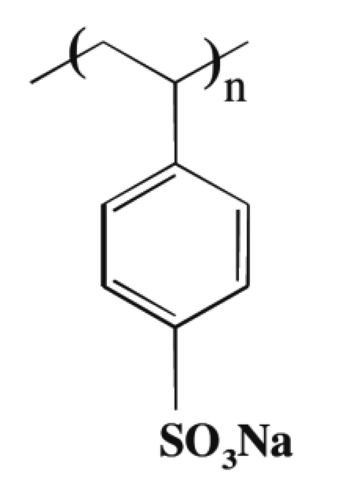
Polyelectrolyte self-assembly is widely applicable technology which is simple in construct, yet stands to gain from further understanding of fundamental processes occurring during the assembly approach [1,2]. This is particularly true when coating nanomaterials—as ionic concentrations in the near surface regions may be drastically different from bulk concentrations due to radius of curvature considerations alone. Ariga et al. highlight several works aimed at elucidating the fundamentals of physico-chemical processes occurring during polyelectrolyte self-assembly [2]. Most notably is the reported ubiquitous relationship between multilayer film formation and the properties of polyelectrolytes in solution. It is reported that low linear charge density polyelectrolytes, which occurs in the presence of increased salt concentration, continue to form multilayers via nonelectrostatic interactions [2]. The conformation of polyelectrolytes in solution is controlled by the effective charge on the polyion. Weakly charged polyelectrolytes, i.e., those whose charge has been compensated for by the presence of counterions in solution, tend to collapse into spherical morphologies [3] and adsorb onto oppositely charges surfaces with greater film thicknesses, relative to rod-like morphologies [4]. This change in film thickness is potentially associated with the adsorption of spherically collapsed morphologies. Strongly charged polyelectrolytes form rod-like molecular morphologies. One of the first models to account for conformation changes in polyelectrolytes associated with counterion condensation was described by Manning [5]. The Manning model has since been used as a starting point to examine conformational changes in polyelectrolytes due to the presence of (and coulombic interaction with) monovalent and multivalent counter ions [6-8]. The Manning model has also been used for examining mobility of polyelectrolytes present in solution with counterions [9,10]. The Manning model proposes that counterion condensation on the polyion backbone occurs until a resulting lowered effective charge on the polyion is achieved. In the case of polystyrene sulfonate (PSS), the effective charge is reduced to less than 40% of the theoretical fully ionized charge via counterion adsorption [3]. The solution retains a concentration of counterions equivalent to the unneutralized charges on the polymer. The counterions in solution are treated with the Debye-Huckel model [5]. In the Manning model, the polyelectrolyte is envisioned as an infinite line of charge comprised of monomer units each having a point charge of −Zpe with the distance between each monomer unit of ℓ [3]. Figure 1 shows the monomer unit of sodium polystyrene sulfonate (PSS), the polyelectrolyte used in this study. Bringing a point charge counter ion having charge +Zce from infinity to within a distance x (in a plane perpendicular to the bisector of the line of charge) of the line of charge will change in the electrostatic potential energy (V(x)) by
In the Manning model, V(x) = 0 is taken at xo = unity. The partition sum, Z (related to the Helmholtz free energy of the system), is given by:
The mathematical criterion for counterion condensation is avoidance of a diverging partition sum at monomer spacing closer than the Bjerrum length, ℓB, times the electrostatic point charges, ZcZp. That is to say, at the condition
A significant conclusion of the Manning condensation theory is that so long as counterions (such as Na+ and H+) are present in large enough quantities to compensate charges until ℓB = ℓ, these ions will condense onto the polyion resulting in both change in conformation to the spherical coil and reduction in polyionic effective charge.
The sp2 hybridized carbons on nanotubes and graphene have electronic structures which are still under debate in the literature. The key arguments surround whether the sp2 hydridized orbitals remain as H or O terminated groups, as free radicals, adopt the carbene structure at zigzag sites with two lone pair electrons, or adopt the carbine structure at armchair sites having a triple bond nature [11]. The nature of the processing approach will dictate surface termination—and thus, dictate the interaction of nanotubes with various ions in solution [12,13]. It is well-documented that carbon nanotubes are able to absorb anions such as Br− [12] as well as heavy metal cations such as Ni2+, Zn2+ and Pb2+ [13]. The preferential adsorption of Ni2+ cations on oxidized multiwalled carbon nanotubes proved to follow the Langmuir adsorption isotherm model [13]. Analyzed using the Langmuir model, as produced CNTs and oxidized CNTs show Ni2+ uptake concentrations of 18.08 mg Ni2+/g-CNT and 9.26 mg Ni2+/g-CNT, respectively [13]. The binding of ions near the surface of carbon is pH dependent [13]— indicating that H+ and OH− ions adsorbed near CNT surfaces mitigate cation and anion adsorption from solution. As well, EXAFS experiments indicate a multiplicity of near surface sites for ionic binding [12]. For example, adsorbed Br− ions measured by EXAFS were determined to reside above the carbon surface at distances which vary from 2.67 Å to 4.52 Å [12]. The adsorption of ions from solution by carbon nanotubes is a key aspect in explaining the morphology adopted by polyelectrolytes when adsorbed onto nanotube surfaces.
This paper seeks to describe the morphology of PSS adsorbed onto the surface of carbon nanotubes and to discuss the role of surface adsorption of cations on carbon nanotubes in structuring the conformation of PSS into spherical-like morphologies. Results show that PSS adsorbs at the nanotube surface in a spherically coiled morphology and disperse CNT bundles into individual tubes which remain in suspension for days.
2. Results and Discussion
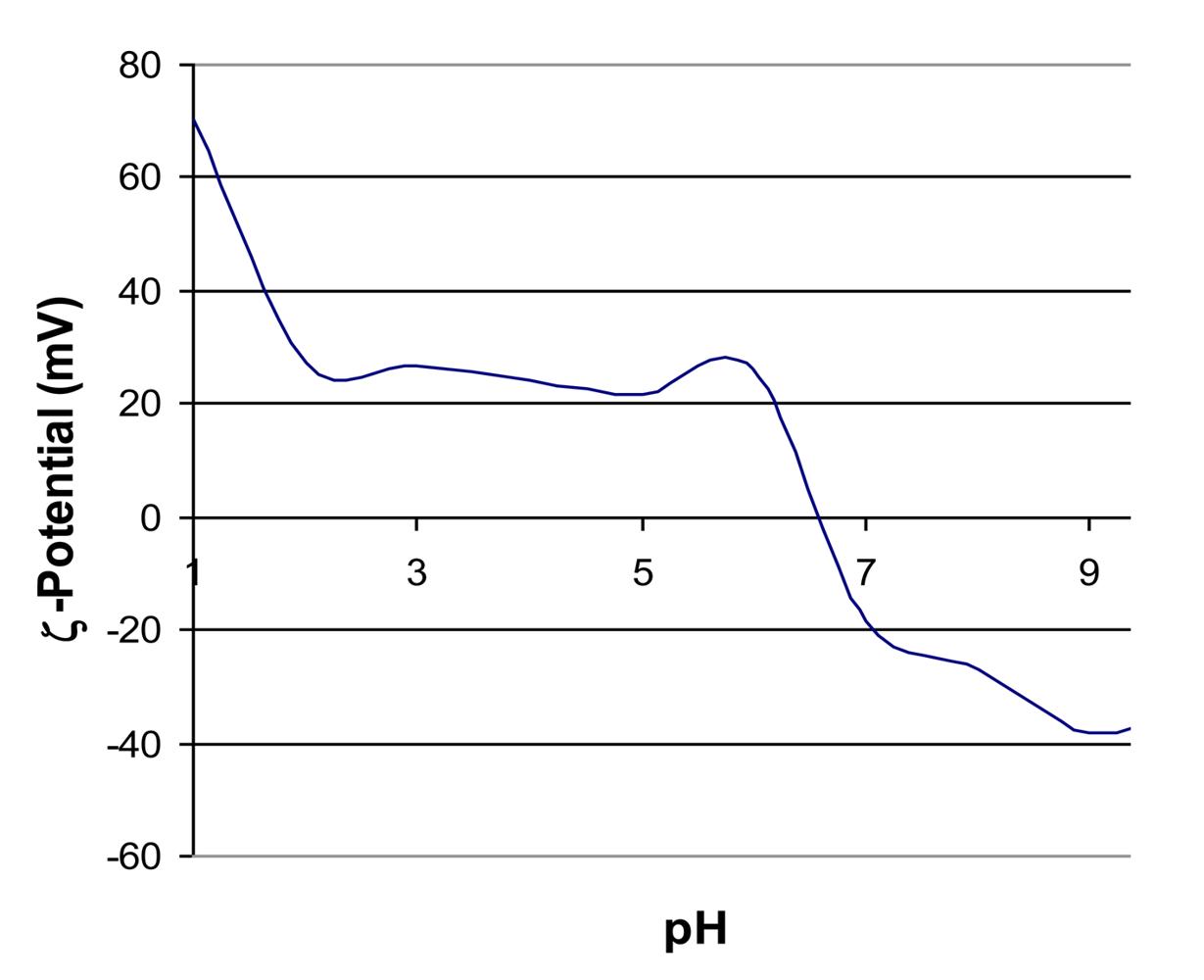
The approach taken in driving the adsorption of PSS onto SWNT surfaces is the electrostatic layer-by-layer (LbL) approach—in which positively charged SWNT surfaces coulombically attract the PSS polyanion. The net positive charge on the SWNT surfaces are formed by adjusting the pH of the aqueous medium to a value at which the electric double layer around the CNT is terminated by positive H+ ions. Here, the LbL reaction is terminated after the deposition of one layer of PSS over SWNT surfaces. Positively charged SWNTs are achieved at pH values below 6.5 [13], Figure 2 shows the surface charge (in mV) of as-purchased SWNTs as a function of pH at values ranging from 1 to 9. The surface charge varies from +70 mV (at pH of 1) to lower than −35 mV (at pH of 9). Surface charges of greater than |ζ| = 30 mV generate stable colloidal suspensions due to electrostatic repulsion of nm-scale entities. The working pH used for electrostatic assembly of PSS anion is 3—and at this pH the SWNTs have a positive charge just above +20 mV. Ultrasonication, therefore, plays a role in maintaining the SWNTs in a suspended state while ionic interactions at their surfaces occur.
2.1. Morphology of PSS at SWNT Surfaces
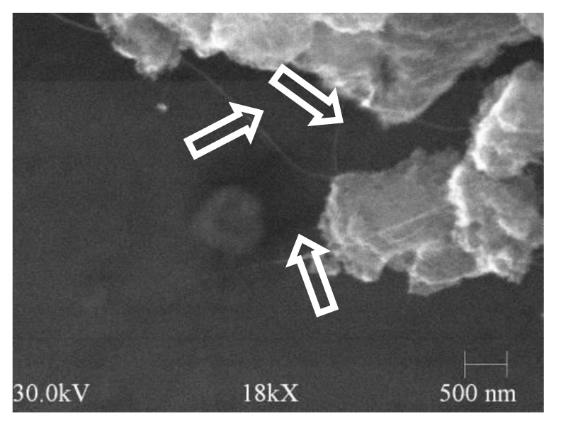
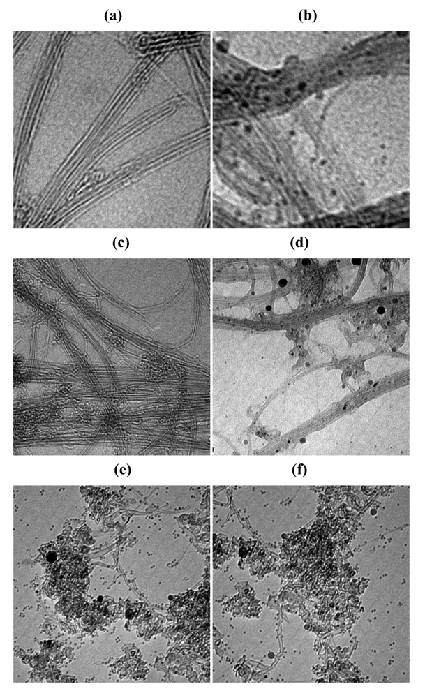
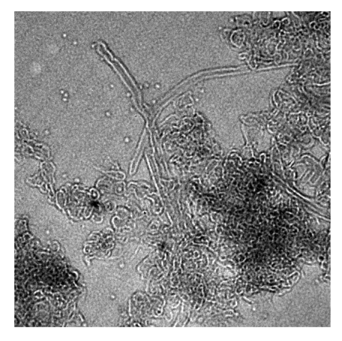
As-purchased, purified SWNTs show two levels of agglomeration: (i) μm scale aggregates (shown by SEM in Figure 3) and (ii) nm-scale bundles (shown by TEM in Figure 4(a,b)). Even at the low magnification of 18 kX in SEM, SWNT bundles (see arrows) are seen to extend from the larger aggregates. High resolution TEM of aggregate regions (Figure 4(e,f)) shows the μm scale aggregates to be comprised of mechanically interlocked or “tangled” SWNTs whose morphology is unable to be altered with the chemical approaches used here. The binding between bundles comprised of straight parallel SWNTs is, however, chemically addressed by cations and the PSS anions in solution.
TEM shows the PSS anion to adopt spherically collapsed conformations at the SWNT surfaces (Figure 4(b,d–f)). These spherically collapsed PSS morphologies are observed both in regions of aggregates and bundles. Samples prepared without ultrasonication show, on average, larger spherical PSS than those found in the sample ultrasonicated for 20 hours indicating that each sphere is comprised of multiple units of polyelectrolytes which then associate by weak Van der Waals interactions. The spherically collapsed conformation is known to occur as a result of counterion condensation onto monomer units of the PSS polyelectrolyte. Suspensions of PSS and SWNTs contain H+ and Na+ ions which may adsorb onto PSS. Typically, LbL films comprised of PSS and a polycation (such as polyallylaminehydrochloride, PAH) deposited at the working pH of 3 and with the same abundance of Na+ counterions present in solution show a planar polyelectrolyte morphology with each layer having a thickness of 2 nm [14-16]. Spherically coiled polyelectrolyte diameters of 40 nm are predicted by continuum models for molecular chains of 250 nm length [17]. Here, the observed PSS spherically coiled diameter varied between ∼2 nm (the order of the SWNT diameter) and ∼200 nm (for some of the largest PSS coils observed). The size variations in coiled diameter are, perhaps, related to ultrasonication which would inhibit the aggregation of multiple PSS polymeric units. After exposure of the sample to the 120 kV electron beam in TEM for periods of 1 hour, the spherically coiled PSS regions were removed by beam damage (Figure 5). Literature reports beam damage to CNTs at 100 kV [18], but here the electron beam did little to further damage the SWNT wall structures. Due to prolonged ultrasonication, the SWNTs suffered some loss in structural order and the straight parallel walls are buckled in some areas shown in Figure 4(e,f).
2.2. Manning Theory of Counterion Condensation for Spherically Coiled PSS at SWNT Surfaces
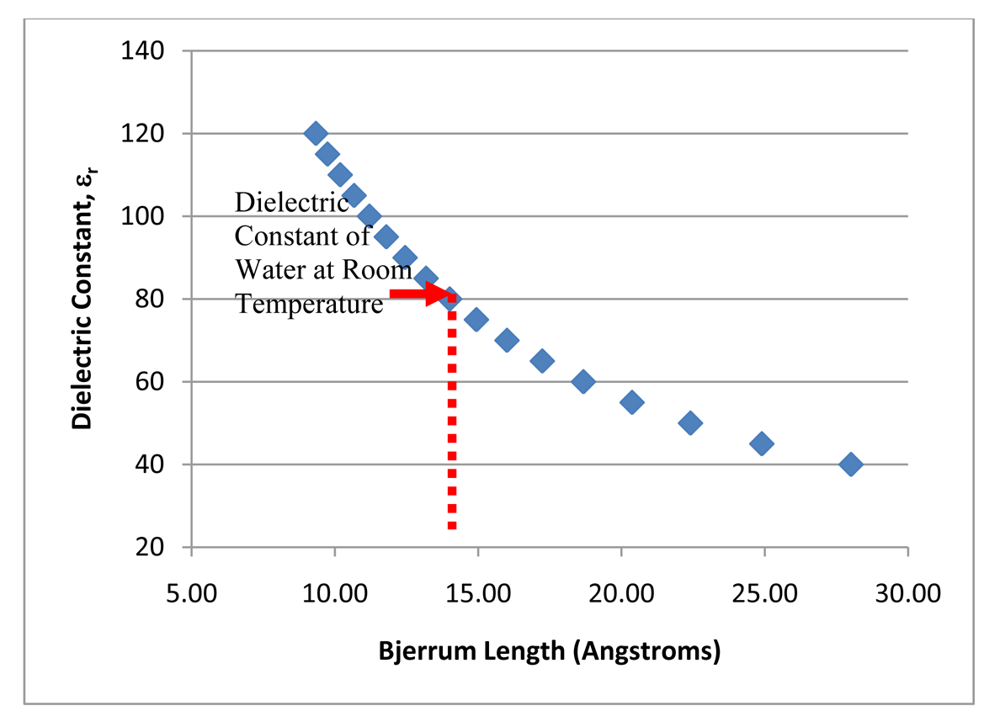
The Manning theory of counterion condensation can be used to predict the spacing of counterions adsorbed onto PSS at the onset of spherical coiling by Equation (5). Alternatively, the theory can be used to explore the ranges of local dielectric constants which must exist near PSS in order to cause the onset of spherical coiling. Figure 6 shows dielectric constant (εr) as a function of Bjerrum length (ℓB) and may be interpreted to yield the spacing, in this case less than 1.3 nm, between counter ions (e.g., Na+ or H+) adsorbed onto PSS for spherical coiling of PSS to occur in pH neutral water at room temperature. In practice, spherical coiling of PSS is not observed in pH 3 aqueous solutions—and so, the condensation limit of 1.3 nm spacing is not reached by counterions in solutions comprised of Na+ (in concentrations found in 2 mg/mL of PSS) and H+ (in concentrations at pH 3). In other words, within the bulk solutions containing Na+ and H+ counter ions, inherent kinetic limitations which control the rate at which counterions enter the coulombic potential of the PSS monomer unit prohibits adsorption of counterions onto the PSS rod-like linear chain backbone with spacing equal to the theoretical Bjerrum length, ℓB = 1.3 nm. Because spherically coiled PSS morphologies are observed at the surface of SWNTs, it can be speculated that the counterions attracted to the surface of SWNTs pre-concentrate the solution—giving local dielectric constants (εr) greater than 80 and resulting in the condensation counterions at theoretical Bjerrum lengths of 1.3 nm or less. Thus, it may be concluded that dielectric constants, (and cationic concentrations) within the solution near the surface of SWNTs is much different from the bulk solution. Experimental work by Duque et al. [19] report changes in SWNT “immediate environment” as a function of changing pH (toward acidic values) by measured fluorescence data. These changes are not attributable to protonation of the CNT (a covalent interaction)—and can be presumed as an increase in local concentration of H+ surrounding the CNT in hydrogen ion rich environments [19]. Furthermore, pH associated confirmation changes of the ionic polymer, PVP, used in that work shows spherically coiled morphologies occur at neutral and high pH while elongated rod-like morphologies occur at low pH. The PVP molecule contains hydrophobic and hydrophilic groups which dictate its conformational structure [19]. Computational research which calculated dielectric constants for biomolecular polyelectrolytes, protein [20] and DNA [18] are useful to discuss here.
That work shows counterion distributions calculated by Poisson-Boltzmann finite-difference models might be more adequately accounted for by assuming a dielectric constant (εr) near the surface of polyelectrolytes which is much different from that in the bulk media. Lamm et al. [21]. use an εr much lower than 80, a value of 10–30 near the polyelectrolyte surface, which increases to 78.5 in the bulk solution. Contour mapping of the near surface dielectric constant (εr), and its associated potential gradient, adequately describes binding sites for ligands and counterions [21]. Although, debate in the literature exists as to whether dielectric constant would adequately describe ligand binding [20]—the argument that near surface dielectric constants may be much different than bulk is validated by the computational study.
Understanding the structure and morphology of polyelectrolytes at the surface of SWNTs is of key relevance because polyelectrolyte self-assembly approaches are currently being used to explore the fabrication of functional coatings containing carbon nanotubes [22-24]. Applications considered are as antimicrobial films [22], electrodes [23], biosensors [24,25], and in the formation of conductive paper [26]. Polyelectrolyte self assembly is presently being used to coat a diverse set of nanomaterials, including biomolecules, proteins, clay platelets, nanorods and nanowires [1,2,26,27]. The surface chemistry of the starting material, in each case, will dictate the propensity for pre-concentration of ions from the working solvent—and hence control polyelectrolyte morphologies. Further studies might consider examining polyelectrolyte morphology and Bjerrum length (ℓB) as a measure of ionic preconcentration at near surface regions for a wide set of nanomaterials chemistries.
2.3. Behavior of PSS-Coated SWNTs in Aqueous Suspensions
The ability to form stable suspensions of SWNTs will prove to be key to their use in a variety of new applications. Non-covalent functionalization of SWNTs is an important strategy to generating stable SWNT suspensions because it leaves the intrinsic electronic properties of the SWNT undisturbed [28]. Several non-covalent strategies for SWNT dispersion have included the use of surfactants [29], DNA [30], and peptides [31]. In order to quantatively examine PSS-SWNT dispersion, supernatants of PSS-SWNT suspensions were examined using UV-Vis spectrophotometry.
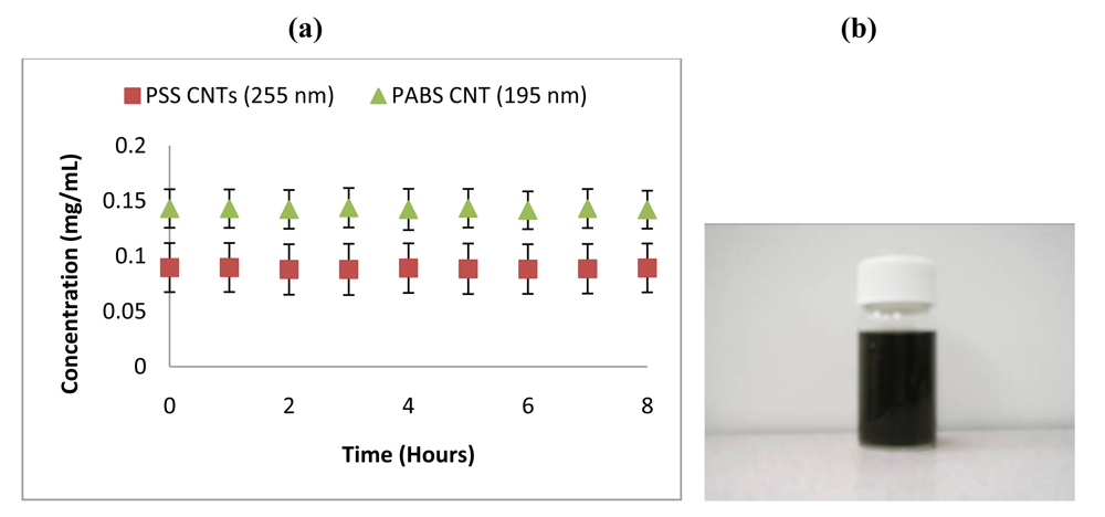
These supernatants exclude SWNT aggregates which have settled out of suspension. The commercial PABS-CNT samples were measured for comparison. Figure 7(a) shows concentration vs. time profiles for PSS-SWNT and PABS-CNTs. Little change in supernatant concentration is observed over an 8 hour period indicating highly stable suspensions are attained via PSS-overlay. At inset, Figure 7(b) shows a photographic image of an PSS-SWNT dispersion in water after 5 hours of ultrasonication. The photographed dispersions contain 0.36 mg/mL of SWNTs with 2 mg/mL of PSS and the image shows the suspension 2 days after it was prepared.
3. Experimental Section
3.1. Preparation of PSS Films at Single Walled Carbon Nanotube (SWNT) Surfaces
For assembly of polystyrene sulfonate (PSS) over SWNT surfaces, mixtures comprised of PSS (Sigma-Aldrich) and commercial purified grade single walled carbon nanotubes (MicroTechNano Corp.) were prepared under pH 3 aqueous conditions. The starting materials were mixed in concentrations of 2 mg/mL of PSS and 0.4 mg/mL of SWNTs. Prior to adding PSS and SWNTs, the pH of deionized water was adjusted to 3 using HCl. One mixture was ultrasonicated for 20 hours with the temperature of the ultrasonic bath reaching up to 60 °C. A second mixture underwent no ultrasonication, but was contained in the pH 3 aqueous solution environment for 20 hours.
3.2. Characterization of Suspensions by UV Visible Spectrophotometry
The absorbance of the solutions was measured using the DU® 530 UV-Vis spectrophotometer scan wavelength mode. To quantitatively determine SWNT suspension concentration vs. time using the Beer-Lambert law, standard suspensions containing known SWNTs concentrations were prepared at 0.1 mg/mL, 0.05 mg/mL, 0.025 mg/mL and 0.0125 mg/mL. For these standards, the suspensions were prepared using pH 3 deionized water with PSS added in the content of 2 mg/mL. The suspensions were ultrasonicated for 5 hours. A total of six absorption measurements were made at the wavelength of 255 nm and the mean of those measurements was fit to a linear regression curve used as a standard concentration line to evaluate sample suspensions. For comparison, suspensions of commercially available polyaminobenzenesulfonic acid (PABS) functionalized carbon nanotubes (CNTs) (Sigma-Aldrich) were prepared in concentrations of 0.2 mg/mL, 0.1 mg/mL, 0.05 mg/mL, and 0.025 mg/mL. The PABS molecule is covalently bound to the CNTs and these CNTs remain in suspension for long periods. The PABS-CNTs suspensions were ultrasonicated for 5 minutes. Two absorption measurements were made at the 195 nm wavelength and the mean of those measurements were fit to a regression curve.
The UV-Visible absorption from PSS-SWNT mixtures prepared at 2 mg/mL of PSS and 0.4 mg/mL of SWNTs was measured at 1 hour intervals for an 8 hour period using a 255 nm wavelength. The results reported comprise the mean and standard deviation (error bars) for six measurements collected within the first 1 minute of each interval. Similarly, the absorption of PABS-CNT suspensions prepared at 0.2 mg/mL was measured over an 8 hour window at 195 nm wavelength.
3.3. Characterization of SWNTs by Electron Microscopy
Scanning electron microscopy (SEM, HITACHI, model S-4,800) was performed on the as-purchased SWNTs at 30 kV electron energy. Transmission electron microscopy (TEM) was performed using the Zeiss Libra instrument. For as-purchased CNT powders, sample preparation involved transfer of the dry powders to sample holders. For PSS-CNT mixtures, sample preparation involved dropwise addition of as-prepared mixtures, both with and without ultrasonication, to the sample holder grids. A drying period of one to several days was performed in an evacuated chamber.
3.4. Surface Charge Measurement of As-Purchased SWNTs
Surface charge ζ-potential measurements were collected using the ZetaPlus Analyzer (Brookhaven Instruments, Holtsville, NY). ζ-potential measurements were taken for SWNTs at various pH values as a means of determining the counterion H+ content around the SWNT surface. For sample preparation, SWNT were added to deionized water having fixed pH values between 3 and 8 at concentrations of 0.1 mg/mL, 0.5 mg/mL and 1 mg/mL. The surface charge was the same for all three SWNT concentrations measured.
4. Conclusions
The polyelectrolyte Na+-PSS organizes over the surface of single walled carbon nanotubes (SWNTs) as spherically collapsed colloids as observed by TEM. The structural organization of polyelectrolytes at the surface of SWNTs is important to understand—because self-assembly approaches are commonly used to fabricate SWNT thin films for specific applications. The overall performance of those films may be enhanced or limited by the surface arrangement of the polyelectrolyte. An explanation for this morphology is that a cation concentration gradient near the SWNT surface would expose the PSS to environments where the Bjerrum length (ℓB) for condensation of counterions and spherical coiling would be achieved. The resulting PSS-SWNTs are stable in aqueous suspension.


Acknowledgments
Funding for this project was provided by the Force Research Laboratory Materials and Manufacturing Directorate (contract FA8650-05-D-1912 A). Undergraduate summer student researcher support from the JFAP Summer Research Experience (Louisiana Tech University and Grambling State University) is gratefully acknowledged.
References
- Ariga, K.; Hill, J.P.; Lee, M.V.; Vinu, A.; Charvet, R.; Acharya, S. Challenges and Breakthroughs in Recent Research on Self-Assembly. Sci. Technol. Adv. Mater. 2008, 9, 014109. [Google Scholar]
- Ariga, K.; Hill, J.P.; Ji, Q. Layer-by-Layer Assembly as a Versatile Bottom-up Nanofabrication Technique for Exploratory Research and Realistic Application. Phys. Chem. Chem. Phys. 2007, 9, 2319–2340. [Google Scholar]
- Muthukumar, M. Theory of Counter-Ion Condensation on Flexible Polyelectrolytes: Adsorption Mechanism. J. Chem. Phys. 2004, 120, 9343–9350. [Google Scholar]
- Linse, P. Adsorption of Weakly Charged Polyelectrolytes at Oppositely Charged Surfaces. Macromolecules 1996, 29, 326–336. [Google Scholar]
- Manning, G.S. A Limiting Law for the Conductance of the Rod Model of a Salt-Free Polyelectrolyte Solution. J. Chem. Phys. 1975, 79, 262–265. [Google Scholar]
- Solis, F.J.; de la Cruz, M. Collapse of Flexible Polyelectrolytes in Multivalent Salt Solutions. J. Chem. Phys. 2000, 112, 2030–2035. [Google Scholar]
- Micka, U.; Kremer, K. Persistence Length of the Debye-Huckel Model of Weakly Charged Flexible Polyelectrolyte Chains. Phys. Rev. E 1996, 54, 2653–2662. [Google Scholar]
- Schafer, H.; Seidel, C. Structure of Polyelectrolytes in Solution: A Monte Carlo Study. Macromolecules 1997, 30, 6658–6661. [Google Scholar]
- Nagasawa, M.; Noda, I.; Takahashi, T.; Shimamoto, N. Transport Phenomena of Polyelectrolytes in Solution under Electric Field. J. Chem. Phys. 1972, 76, 2286–2294. [Google Scholar]
- Hoagland, D.A.; Arvanitidou, E.; Welch, C. Capillary Electrophoresis Measurements of the Free Solution Mobility for Several Model Polyelectrolyte Systems. Macromolecules 1999, 32, 6180–6190. [Google Scholar]
- Radovic, L.R.; Bockrath, B. On the Chemical Nature of Graphene Edges: Origin of Stability and Potential for Magnetism in Carbon Materials. J. Am. Chem. Soc. 2005, 127, 5917–5927. [Google Scholar]
- Kandah, M.I.; Meuner, J.L. Removal of Nickel Ions from Water by Milt-Walled Carbon Nanotubes. J. Hazard. Mater. 2007, 146, 283–288. [Google Scholar]
- Mehta, A.; Nelson, E.J.; Webb, S.M.; Holt, J.K. The Interaction of Bromide Ions with Graphitic Materials. Adv. Mater. 2009, 21, 102–106. [Google Scholar]
- Lvov, Y; Haas, H.; Decher, G.; Mohwald, H. Successive Deposition of Alternate Layers of Polyelectrolytes. Langmuir 1994, 10, 4232–4236. [Google Scholar]
- Park, S.Y.; Rubner, M.F.; Mayes, A.M. Free Energy Model for Layer-by-Layer Processing of Polyelectrolyte Multilayer Films. Langmuir 2002, 18, 9600–9604. [Google Scholar]
- Kamineni, V.K.; Lvov, Y.M.; Dobbins, T.A. Layer-by-Layer Nanoassembly of Polyelectrolytes Using Formamide as the Working Medium. Langmuir 2007, 23, 7423–7427. [Google Scholar]
- Drouot, R.; Maugin, G.A. Continuum Modelling of Polyelectrolytes in Solution. Rheol. Acta 1985, 24, 474–487. [Google Scholar]
- Kiang, C.-H.; Goddard, W.A.; Beyers, R.; Bethune, D.S. Structural Modification of Single-Layer Carbon Nanotubes with an Electron Beam. J. Phys. Chem. 1996, 100, 3749–3752. [Google Scholar]
- Duque, J.G.; Cognet, L.; Parra-Vasquez, A.N.G.; Nicholas, N.; Schmidt, H.K.; Pasquali, M.J. Stable Luminescence from Individual Carbon Nanotubes in Acidic, Basic, and Biological Environments. J. Am. Chem. Soc. 2008, 130, 2626–2633. [Google Scholar]
- Warshel, A.; Papazyan, A. Electrostatic Effects in Macromolecules: Fundamental Concepts and Practical Modeling. Curr. Opin. Struct. Biol. 1998, 8, 211–217. [Google Scholar]
- Lamm, G.; Pack, G.R. Calculation of Dielectric Constants near Polyelectrolytes in Solution. J. Phys. Chem. B 1997, 101, 959–965. [Google Scholar]
- Nepal, D.; Balasubramanian, S.; Simonian, A.L.; Davis, V.A. Strong Antimicrobial Coatings: Single-Walled Carbon Nanotube Armored with Biopolymers. Nanoletters 2008, 8, 1896–1901. [Google Scholar]
- Lee, S.W.; Kim, B.S.; Chen, S.; Horn, S.Y.; Hammond, P.T. Layer-by-Layer Assembly of All Carbon Nanotube Ultrathin Films for Electrochemical Applications. J. Am. Chem. Soc. 2009, 131, 671–679. [Google Scholar]
- Zhao, H.; Ju, H. Multilayer Membranes for Glucose Biosensing via Layer-by-Layer Assembly of Multiwall Carbon Nanotubes and Glucose Oxidase. Anal. Biochem. 2006, 350, 138–144. [Google Scholar]
- Zykwinska, A.; Radji-Taleb, S.; Cuenot, S. Layer-by-Layer Functionalization of Carbon Nanotubes with Synthetic and Natural Polyelectrolytes. Langmuir 2010, 26, 2779–2784. [Google Scholar]
- Agarwal, M.; Xing, Q.; Shim, B.S.; Kotov, N.; Varahramyan, K.; Lvov, Y. Conductive Paper from Lignocellulose Wood Microfibers Coated with a Nanocomposite of Carbon Nanotubes and Conductive Polymers. Nanotechnology 2009, 20, 215602. [Google Scholar]
- Shchukin, D.G.; Sukhorukov, G.B.; Price, R.R.; Lvov, Y.M. Halloysite Nanotubes as Biomimetic Nanoreactor. Small 2005, 1, 510–513. [Google Scholar]
- Moreno, M.S.; Salavagione, H.J.; Hernandez, J.C.; Midgley, P.A.; Morallon, E.; Barbero, C.; Morales, G.M. Polyelectrolyte-Assisted Solubilization and Metal Decoration of Carbon Nanotubes. Dual Role of PEDOT-PSS. Acta Microsc. 2009, 18, 61–62. [Google Scholar]
- Strano, M.S.; Moore, V.C.; Miller, M.K.; Allen, M.J.; Haroz, E.H.; Kittrell, C.; Hauge, R.H.; Smalley, R.E. The Role of Surfactant Adsorption during Ultrasonication in the Dispersion of Single-Walled Carbon Nanotubes. J. Nanosci. Nanotech. 2003, 3, 81–86. [Google Scholar]
- Zheng, M.; Jagota, A.; Semke, E.D.; Diner, B.A.; McLean, R.S.; Lustig, S.R.; Richardson, R.E.; Tassi, N.G. DNA-Assisted Dispersion and Separation of Carbon Nanotubes. Nat. Mater. 2003, 2, 338–342. [Google Scholar]
- Dieckmann, G.R.; Dalton, A.B.; Johnson, P.A.; Razal, J.; Chen, J.; Giordano, G.M.; Munoz, E.; Musselman, I.H.; Baughman, R.H.; Draper, R.K. Controlled Assembly of Carbon Nanotubes by Designed Amphiphilic Peptide Helices. J. Am. Chem. Soc. 2003, 125, 1770–1777. [Google Scholar]
© 2011 by the authors; licensee MDPI, Basel, Switzerland. This article is an open access article distributed under the terms and conditions of the Creative Commons Attribution license (http://creativecommons.org/licenses/by/3.0/).
Share and Cite
Dobbins, T.; Chevious, R.; Lvov, Y. Behavior of Na+-Polystyrene Sulfonate at the Interface with Single-Walled Carbon Nanotubes (SWNTs) and Its Implication to SWNT Suspension Stability. Polymers 2011, 3, 942-954. https://doi.org/10.3390/polym3020942
Dobbins T, Chevious R, Lvov Y. Behavior of Na+-Polystyrene Sulfonate at the Interface with Single-Walled Carbon Nanotubes (SWNTs) and Its Implication to SWNT Suspension Stability. Polymers. 2011; 3(2):942-954. https://doi.org/10.3390/polym3020942
Chicago/Turabian StyleDobbins, Tabbetha, Richard Chevious, and Yuri Lvov. 2011. "Behavior of Na+-Polystyrene Sulfonate at the Interface with Single-Walled Carbon Nanotubes (SWNTs) and Its Implication to SWNT Suspension Stability" Polymers 3, no. 2: 942-954. https://doi.org/10.3390/polym3020942