Review

Design and Synthesis of Cross-Linked Copolymer Membranes Based on Poly(benzoxazine) and Polybenzimidazole and Their Application to an Electrolyte Membrane for a High-Temperature PEM Fuel Cell

1
Energy Lab, Samsung Advanced Institute of Technology, Samsung Electronics Co., Ltd., Nongseo-dong, Giheung-gu, Gyeonggi-do 446-712, Korea
2
Department of Chemical and Biological Engineering, Seoul National University, 599 Gwanak-ro, Gwanak-gu, Seoul 151-744, Korea
*
Author to whom correspondence should be addressed.
Polymers 2013, 5(1), 77-111; https://doi.org/10.3390/polym5010077
Submission received: 27 December 2012 / Revised: 16 January 2013 / Accepted: 17 January 2013 / Published: 23 January 2013

Abstract

:
Elevated-temperature (100~200 °C) polymer electrolyte membrane (PEM) fuel cells have many features, such as their high efficiency and simple system design, that make them ideal for residential micro-combined heat and power systems and as a power source for fuel cell electric vehicles. A proton-conducting solid-electrolyte membrane having high conductivity and durability at elevated temperatures is essential, and phosphoric-acid-containing polymeric material synthesized from cross-linked polybenzoxazine has demonstrated feasible characteristics. This paper reviews the design rules, synthesis schemes, and characteristics of this unique polymeric material. Additionally, a membrane electrode assembly (MEA) utilizing this polymer membrane is evaluated in terms of its power density and lifecycle by an in situ accelerated lifetime test. This paper also covers an in-depth discussion ranging from the polymer material design to the cell performance in consideration of commercialization requirements.

1. Introduction

The interest in renewable energy has been growing over the past few decades owing to the concern over CO2 pollution and the shortage of fossil fuels. Among the candidates for a renewable energy source, fuel cells offer certain advantages because they can be used in a wide variety of applications, such as portable devices, in vehicles, and for residential power generation. Vehicular applications perhaps offer the largest market and will have the greatest impact on the environment. The volatile price of oil and the concerns over air pollution have positioned fuel cell vehicles as the main candidates to replace the internal combustion engine (ICE) system in the automobile industry. The targets for the fuel cell before it enters the vehicle market include durability, price and safety. These three targets apply to all applications. The proton exchange membrane fuel cell (PEMFC), which operates in the temperature range of 60 to 80 °C, is being developed by many automobile makers [1,2]. This fuel cell system uses sulfonated polymer as the electrolyte, and the high proton conductivity of the membrane and the high power density of the fuel cells allow it to generate as much as 100 kW power. Sulfonated polymer has many advantages, but it requires humidification and has operation temperatures under 100 °C. Operations to provide continuous humidification to the membrane can increase the cost of the fuel cell system, and the low operation temperature requires the vehicle to have a larger cooling system. The problem of the operating temperature remaining at less than 100 °C in a humidified condition has introduced the need to develop a new electrolyte that can operate at temperatures between 120 and 140 °C under lower humidification conditions. However, it is difficult to design a membrane that can operate with no humidification because sulfonated polymers require water so that they can act as a proton-conducting medium.
There has been some interest in phosphoric-acid-based PEMFC systems because they do not require humidification, and offer high tolerance to CO [2,3]. These advantages can simplify the fuel cell system design by removing the humidifier and adapting a simpler reformer. Polybenzimidazole (PBI) is usually used as membrane for a phosphoric-acid-based PEMFC [4,5,6]. PBI has excellent durability at temperatures up to 200 °C and retains its mechanical strength, even after absorbing phosphoric acid [7]. The membrane electrode assembly (MEA), which uses a phosphoric-acid-doped membrane, operates in the temperature range of 150 to 180 °C. These high-temperature PEMFC systems require no humidification when they operate in a fuel cell system. The target market for fuel cell systems that use phosphoric-acid-based MEA are portable and residential applications. In order to be applied in these fields, the fuel cell systems need to be less expensive and more durable such that they can operate for more than 40,000 h. The properties of the membrane are critical for achieving the durability targets of the fuel cell system, and many recent works have been reported to enhance the performance of the membranes used in high-temperature PEMFCs [8,9].
In this review, the advantages that the high-temperature PEMFC systems have over low-temperature PEMFC systems, as well as the requirements and recent developments as regards the membrane that can be used in a high-temperature PEMFC MEA, will be discussed. In addition, the core technologies and development background of other components, including the catalyst and stack, are discussed in the following chapters.

2. Core Technologies and Issues

2.1. Catalyst

A catalyst is defined as a material that can enhance the rate of a chemical reaction without a change or one that can disappear as a result of a chemical reaction. Especially for electrochemical reactions, a catalyst is referred to as an electrocatalyst, which is an essential material in a MEA to produce the electron and proton as a result of the hydrogen oxidation reaction (HOR) involving the anode and water from oxygen caused by the oxidation reduction reaction (ORR) of the cathode for a PEMFC to reduce the overpotentials in the following Equations (1–3).
Anode: 2H2 →4H+ + 4e
Cathode: O2 + 4H+ + 4e → 2H2O
Overall Cell Reaction: 2H2 + O2 → 2H2O
Historically, the Pt electrode was used in the first experiment to prove the principles of a fuel cell by William Robert Grove in 1839 [10]. Since then, Pt and platinum-group metals have been the main elements for electrocatalysts in PEMFCs because the operating condition of a PEMFC is very acidic and corrosive to most other metals. The state-of-the-art electrocatalyst relies on Pt or Pt-alloy nanoparticles with sizes of 2–5 nm that are dispersed on a large surface-area porous carbon support with Pt weight percentages of 20% to 60%. Typically, these are commercially available from Johnson Matthey, Tanaka Kikinzoku Kogyo, or the E-TEK division of BASF Fuel Cells [11].
Since the supported Pt catalyst was introduced as an electrocatalyst for the fuel cell MEA in the 1960s [12], higher activity and longer durability of Pt catalysts have been pursued to decrease the amount of Pt in the MEA and to increase the lifetime of MEA by several approaches [13,14,15,16,17,18]. These include optimizing the preparation method; alloying with other metals such as Co, Ni, or Ru; and controlling the structure of the nanoparticles, such as the core-shell structure, the Pt monolayer or the hollow formations or controlling the dealloying of transition metals from the alloy nanoparticles.
Among these factors, core-shell nanostructures are an effective means of generating improved functionalities in metal nanoparticles, which have an average size between 2 and 10 nm. In principle, the synthesis of core-shell nanostructures is possible when the heterogeneous growth of the second metal on a pre-formed nanoparticle seed or core has a lower energy barrier than that of the homogeneous growth between second metals [16]. However, reports in the literature on the preparation of well-defined core-shell nanoparticles under 10 nm are still not common due to the intrinsic difficulty related to the colloidal process and to the characterization of the structure in detail.
Recently, electrochemical methods such as galvanic replacement and dealloying have been developed for the generation of a Pt monolayer or a segregated Pt shell around the surfaces of the nanoparticles. In particular, the Pt monolayer (skin) electrocatalysts developed mainly by Adzic et al. displayed enhanced oxygen reduction reaction activity and durability [19,20,21,22]. For example, a carbon-supported Pt monolayer on Pd (Pt/Pd/C) and on Pd9Au1 (Pt/Pd9Au1/C) was prepared by means of under-potential deposition and replacement reactions and were done using the potential cycling of MEA between 0.7 and 0.9 V [20,21]. The Pd9Au1 alloy core, which suppressed the dissolution of Pt, a major pathway of degradation of the Pt electrocatalyst in MEA that occurs at the high-potential region under an acidic condition, consequently increased the stability of the Pt/Pd9Au1/C electrocatalyst, exceeding the target set by the DOE [20,21]. Furthermore, the Adzic group suggested very recently that the formation of a Pt hollow structure by the Kirkendal effect can be induced by removing the Ni core electrochemically or chemically, resulting in the lattice contraction of Pt and an increase in the Pt mass activity. This process was also shown to be highly sustainable in potential cycling tests [22].
For a residential application of a PEMFC, natural gas should be converted into hydrogen feed, which is known as reformate gas and which generally contains 5000 ppm of CO in the initial stage and less than 10 ppm at the final stage of reforming. Usually, the performance of a Pt catalyst is reduced greatly by a small amount of CO in the hydrogen feed for a PEMFC due to the strong adsorption of CO by Pt nanoparticles. Thus, considerable effort has been made to decrease the effect of CO on the performance of PEMFCs, including the development of CO-tolerant electrocatalysts such as PtRu/C and PtSn/C [23,24] and attempts to operate PEMFCs at high temperatures to weaken the CO adsorption by Pt. A thermodynamic analysis of the effect of CO on the Pt catalyst showed that the CO tolerance is 10 ppm at 80 °C, 1000 ppm at 130 °C and up to 30,000 ppm for 200 °C, which will offer a cost advantage and mitigate the requirement of CO removal stage during the reforming process. The effect of CO poisoning on the supported Pt catalyst over a range 125–200 °C was investigated with phosphoric acid-doped PBI membranes, showing that the CO tolerance can be sufficiently improved at an elevated temperature [25].
In addition to improving the CO tolerance, the operation of a PEMFC at a high temperature can provide a few advantages in terms of the electrocatalyst, such as increasing the reaction kinetics and facilitating the use of a non-Pt electrocatalyst [23,24,25]. The reaction kinetics for the HOR and ORR will be enhanced by increasing the operation temperature. This is especially true in the case of the ORR [26,27,28]. However, the thermodynamic open circuit voltage (OCV) decreases with an increase in the temperature, especially above 100 °C, due to the increase of the partial pressure of water [23,24,26,27,28]. In addition, the durability of the carbon support and the supported catalyst at a high temperature are among the main challenges when seeking to maintain the performance and durability of a MEA for a high-temperature PEMFC [29].
To realize the use of non-Pt electrocatalysts in our lab, Pd-based alloys for high-temperature PEMFCs have been explored for many years because these electrocatalysts are considered to have the highest level of activity among pure metal elements. They have also been developed by many research groups [30,31,32]. For example, the enhanced oxygen reduction reaction (ORR) activity and a positive shift (40 mV) of the onset potential for the ORR of the PdCo alloy electrocatalyst with nanosized CeOx have both been observed, showing a remarkable increase as the temperature increases due to the oxygen storage capacity of CeOx nanoparticles [33,34]. By means of galvanic replacement, the PdCu alloy was decorated with Ir on the surface of the alloy particles, showing higher single cell performance for a high-temperature PEMFC resulting from the core-shell-like structure of the PdIr–PdCu alloy electrocatalyst [35]. Although some Pd alloy catalysts showed catalytic activity comparable to that of the Pt catalyst, the durability of the Pd alloy is not thoroughly proved, which indicates that further research for improving the stability of Pd alloy catalysts under severe acidic conditions is required.
Besides the catalytic metal components, managing the support in supported catalysts is also important to increase the utilization of the catalytic component by dispersing the metal component on large surface areas. Thus far, activated carbons such as Vulcan XC-72R and Ketjen Black with high electron conductivity and large surface areas have widely been used in commercial electrocatalysts [36,37,38]. To improve the electrochemical activity and stability of the supported catalyst, new carbon materials such as carbon nanotubes, carbon nanofiber, mesoporous carbon and, very recently, graphene or graphene oxide, have been tested as possible superior supports for fuel cell catalysts [36,37,38]. In our lab, ordered mesoporous carbon having ordered mesopores of 3–10 nm between carbon nanorod arrays have been developed and applied to highly dispersed and stabilized Pt-supported catalysts [39,40,41,42,43,44,45,46]. One drawback of carbon as a support is the corrosion of the carbon itself at high voltages under fuel cell operation, resulting in the degradation of the catalyst activity. To overcome this issue, it is necessary to explore the development of non-carbon supports as stable alternatives to replace the carbon materials. Non-carbon materials should meet fundamental property requirements, including a high surface area, high corrosion resistance under dry and humid air conditions, low solubility in acidic media, high electrical stability under fuel cell operation, and high conductivity [47,48].

2.2. Membrane

Because polymer electrolyte membrane (or “proton exchange membrane”) fuel cells (PEMFCs) have gained much attention as a clean energy source, especially in the fields of portable and smaller scale stationary power sources, as they offer a relatively low weight, cost, and volume, as well as a simple production process, the importance of the membrane is increasingly considered to be a key component [49]. However, PEMs using perfluorinated sulfonic acid (PFSA) ionomers, such as Nafion (DuPont; 0.9 meq g−1), have several drawbacks, such as a limited operation temperature (generally <100 °C), high fuel crossover, and a high cost [50]. These shortcomings have hampered their wider commercialization and have triggered extensive research into alternative PEMSes that can perform at elevated temperatures (generally 120–200 °C) and in a low-humidity condition (relative humidity (RH) <50%) [51,52,53,54,55,56,57,58]. Among numerous material candidates, a significant body of literature is devoted to PBI and its derivatives when doped with phosphoric acid (PA) as a PEM in high-temperature fuel cell processes. In particular, poly[2,2'-(m-phenylene)-5,5'-bibenzimidazole] (mPBI, Figure 1a) and poly(2,5-benzimidazole) (ABPBI, Figure 1b) have attracted attention because they exhibit high proton conductivity at temperatures up to 200 °C, low gas permeability, low methanol crossover, excellent oxidative and thermal stability, high mechanical stability, and a water drag coefficient of virtually zero [4,55,59,60,61,62,63,64,65,66,67,68,69,70]. Unlike perfluorosulfonic acid (PFSA) polymers, which require water for proton transport, the proton transport of PA-doped PBI relies on PA due to its lack of volatility when complexed at basic sites with imidazole units in PBI. Despite its obvious advantages, further progress is still required due to critical drawbacks, one of them being the loss of stability of PBI membranes with large amounts of PA [71,72,73]. Increasing the PA content in PBI membranes is beneficial for proton transport but results in the deterioration of the chemical and mechanical stability of these membranes. Enhancing the stability under real operating conditions, such as high temperature and pressure, and with a large PA content in the membrane, is a challenge that needs to be met for the long-term durability of PEMFCs. Compared to PBI, because ABPBI can be prepared from an inexpensive and commercially available single monomer, 3,4-diaminobenzoic acid (DABA), its synthesis and stoichiometry can be balanced very easily, as can monomer purification. Therefore, a high molecular weight (or a large inherent viscosity in the range of 2.3–2.4 dL g−1) in ABPBI can be easily prepared, which can increase the stability of the film [4,71,74,75]. Furthermore, PA-doped ABPBI membranes show higher proton conductivity than PA-doped PBI membranes because ABPBI membranes can absorb more PA. When PA-doped PBI-based membranes have higher PA contents, they show higher proton conductivity. Even when ABPBI membranes have better properties than PBI, they also lose their stability with high PA contents, like PBI membranes. Moreover, the extremely poor solubility of ABPBI membranes in organic solvents is another drawback that prevents their practical application [4,76]. Benicewicz et al. and Lee et al. recently suggested a membrane fabrication process for preparing PA-doped PBI-based membranes without using an organic solvent. Lee et al. referred to this process as direct casting [67,68,73]. In the case of direct casting, the polymerization solution is directly used in the casting step, which may resolve the solubility problem of ABPBI membranes. However, this method cannot be applied to the preparation of PA-doped ABPBI membranes because the ABPBI membranes dissolve in the PA produced by the hydrolysis process, which converts poly(phosphoric acid) (PPA) into PA [75,77].
Polybenzoxazine (PBOA) has been developed as a novel class of phenolic resin for solving the shortcomings associated with traditional phenolic resins [78,79,80,81,82,83,84,85,86,87]. This resin can be synthesized from inexpensive raw materials such as phenols, formaldehyde, and from primary amines through Mannich condensation [88]. Polymerization occurs through the heterocyclic ring opening, affording polymers with linear or cross-linked structures excellent thermal and dimensional stability without byproducts depending on the functionalities of benzoxazine (BOA) units in the Mannich base bridges [–CH2–N(R)–CH2–] (Figure 1c,d). It is important to note that thermosetting resins have many promising properties as a high-temperature PEM material, such as strong mechanical and thermal resistance as well as chemical stability. However, while benzoxazines have been used as cross-linking agents for due to their curing ability over covalently bonding with a host material [89], it is impossible to utilize PBOA itself with the PEM material due to its poor processability, which is typical for thermosetting resins. Moreover, there are very few reports of PBOAs at elevated temperatures in PEM fuel cells.
The core technology of a membrane in SAIT involves enhancing the stability under real operating conditions. These conditions involve high temperatures and pressures as well as a large PA content in the membrane. This is regarded as a challenge that needs to be met for the long-term durability of PEMFCs as well as to improve their economic competitiveness. For this purpose, PBOA, regarded as a difficult material for membrane applications due to its thermosetting characteristics, was adopted as the membrane matrix at more than 65 wt % to overcome the drawbacks of PBI-based membranes. Corresponding copolymer electrolyte membranes have been developed over the last six years in accordance with desired properties ensuring by means of the manifest functionalities developed. However, unlike conventional polymer blending, introducing PBOA must follow a particular process to offset the poor processability of PBOA due to its thermosetting characteristics. The membrane fabrication method chosen here was to mix BOA with PBI via solution blending and to perform subsequent thermal cross-linking followed by conventional tape casting. With the series of fabrication processes suggested by Choi et al. [90,91,92,93], the preparation of cross-linked benzoxazine–benzimidazole copolymer membranes can be done successfully [94]. As part of the effort to counterbalance the weaknesses of PBI-based membranes, we focused on enhancing the necessary properties at the operating temperature and on finished membrane development up to the fourth generation. Also, as part of the process improvement resulting from acid doping after membrane fabrication, the direct casting process suggested by Lee et al. [68,73] was modified and applied as a new type of process to PBI, as well as ABPBI. The technique of introducing PBOA as a membrane matrix under a monomer state greatly contributed to the fabrication of the PBOA-co-ABPBI membrane via direct casting method, resulting in the best cell performance of MEA based on the ABPBI based structure. Further details of this membrane fabrication process will be addressed in the latter part of this review.
Figure 1. Synthesis of (a) polybenzimidazole (PBI); (b) poly(2,5-benzimidazole) (ABPBI); (c) 6-(Tert-butyl)-3-phenyl-3,4-dihydro-2H-benzo[e][1,3]oxazine (pBUa) and P(pBUa); and (d) 6-Fluoro-3-(pyridine-2-yl)-3,4-dihydro-2H-benzo[e][1,3]oxazine (pF) and P(pF) (asterisks indicate possible crosslinking sites).
Polymers 05 00077 g001

2.3. MEA

2.3.1. MEA Background

A membrane electrode assembly (MEA) consists of an anode electrode, a cathode electrode, and a membrane sandwiched between the two electrodes. It produces electricity by enabling gases to react in the cathode and anode electrodes. Electrons are drawn from the anode and passed to the cathode through an external circuit, producing direct current electricity. The ideal voltage resulting from the above reactions is 1.23 V; however, voltage loss occurs during the passage of electrons and protons, and the actual measured cell voltage decreases with an increase in the current density, as shown in Figure 2. In a low current density region, the voltage loss is dominated by the kinetic loss, and the voltage decreases exponentially with an increase in the current. After the current density increases further, ohmic and mass transfer resistances play more significant roles. Ohmic resistance is determined by the proton conductivity of the membrane. In order to achieve high power output at a high current density, which is required for fuel cell applications such as vehicles, it is essential for the membrane to have sufficient proton conductivity. For the membranes applied to fuel cells in vehicles, the DOE target of the area-specific resistance for the membrane is set to 0.02 ohms cm2. A further increase in the current density will cause the MEA to be controlled by the mass transfer of reactant gases in its electrodes. The H2 and O2 gases need to diffuse through the porous electrodes to reach the catalysts. The lack of a reactant gas at the reaction site can lead to an abrupt loss of power. Thus, it is essential to maintain a sufficient path for reaction gases in the electrode.
Figure 2. Current voltage curves.
Polymers 05 00077 g002

2.3.2. MEA Performance

The proton-conducting mechanism in the membrane varies depending on the operation temperature. For fuel cells that operate below 100 °C, water acts as a proton carrier in the membrane, while Nafion and other sulfonated polymers are used as electrolytes. For operating conditions at higher temperatures, such as 150–200 °C, phosphoric acid is used as the proton carrier. In such a system, PBI-based membranes are generally used. Phosphoric acid is impregnated into the membrane, and the electrodes become partially filled with phosphoric acid. The commercially available product CeltecP1000 (BASF Fuel Cell) uses a PBI membrane. The MEA operates in a temperature range of 160 to 180 °C, and it has been reported that this type of MEA can be operated up to 20,000 h [95]. A high-temperature PEMFC shows considerably low cell performance compared to a Nafion-based low-temperature PEMFC MEA. A cell voltage of 0.68 V at 0.2 A cm−2 was reported [95], while 0.8 V was reported for a MEA with Nafion as the electrolyte [96]. The difference in the cell performance is caused by the type of proton carrier in the MEA. The presence of phosphoric acid in the electrodes leads to a low oxygen reduction reaction rate on the catalyst.

2.3.3. Durability of the MEA

During the operation of PEMFC systems, the MEA is exposed to aggressive environments which are characterized by a combination of acidic conditions, high operation temperatures and high electrochemical potentials. Many researchers have conducted investigations in an effort to understand the roles of these various conditions in the degradation process. The MEA performances need to be maintained in various operation modes. During a continuous mode of operation, the slow degradation of the catalyst and membrane causes relatively a linear decay of the cell voltage [97]. However, start and stop operations of systems can cause a different type of catalyst and membrane degradation, leading to even faster cell voltage decay. Thus, it is essential for the components of a MEA to maintain their roles during different types of cell operation. For a high-temperature PEMFC, it is also important to maintain phosphoric acid within the MEA during cell operation. The loss of this acid causes a decrease in the catalyst/acid contact area, leading to a reduction in the number of reaction sites in the catalyst layer. The acid loss also causes a loss of proton conductivity in the membrane; such a loss of proton conductivity can cause a drop in the MEA performance, leading to a failure of high-temperature PEMFC systems. Thus, the ability to retain phosphoric acid is an important characteristic for the membranes used in high-temperature PEMFCs MEA.

2.4. Stack

The main issues in the stack for a high-temperature PEMFC are mainly thermal management and durability. In general, water management is one of the critical issues in a low-temperature PEMFC, but this is less important in a high-temperature PEMFC due to the relatively dry operation condition. In a high-temperature PEMFC, thermal management in terms of a uniform temperature distribution and cooling should be considered. A high operating temperature that exceeds 150 °C makes it difficult to maintain a uniform temperature distribution at all positions of the stack, but it is known that this problem can be overcome through the optimum path design of the coolant and cooling channel and with the use of good insulation. Cooling methods have been studied as a main topic in relation to high-temperature PEMFCs, and various cooling methods such as water cooling, air cooling and oil cooling have been assessed [98,99,100]. Cooling using water and air is mostly done at temperature of less than 100 °C, but passive water cooling using latent heat has also bed used in a high-temperature PEMFC. Oil cooling is mainly used for heat recovery in stationary applications.
Above 100 °C, passive water cooling uses latent heat due to the phase change of water. As a result, it does not require pumps for circulating the coolant because the buoyancy resulting from the phase change generates the driving force. The equipment for passive water cooling consists of a heat exchanger, a reservoir and a solenoid valve, as shown in Figure 3a. Heat recovery is done by secondary coolant at the heat exchanger, and thermostating by on–off control of the solenoid valve is essential [101]. In comparison, oil cooling requires only an expansion tank and a pump, as shown in Figure 3b. Oil cooling can provide a quick response to a transient change of the stack performance on the electric load, and the amount of heat recovered from the stack can be adjusted by controlling the pumping speed and the flow rate. However, a larger heat exchanger is required because heat must be exchanged only by a temperature change of the coolant when cooling the oil.
Figure 3. (a) Schematic diagram of passive water cooling; and (b) schematic diagram of oil cooling.
Polymers 05 00077 g003
Durability is related to many factors, such as the corrosion of components, acid leaks, MEA degradation and sealing failures. Corrosion caused by phosphoric acid constrains the selection of the materials for components such as the gasket, the end plate and the bipolar plate. Materials with resistance to acids, such as fluorocarbon rubber, should be used for gaskets and in the cell design to prevent contact with the acid. Acid leaks from the electrolyte membrane can cause flooding within the electrode and shorten the durability of the separator due to corrosion. It is difficult to avoid acid leaks from the electrolyte due to the compression of the MEA to reduce the electrical resistance between the MEA and the bipolar plate. To solve this problem, efforts to prevent acid leaks using a hard-type gasket (e.g., PTFE) have been tested for their ability to restrain the compression of the MEA.
Compared to a low-temperature PEMFC, understanding the physical and electrochemical phenomena which occur at the MEA and the stack will not provide all of the necessary information. Therefore, modeling to simulate the electrochemical phenomena has been attempted by many researchers. At present, integrated modeling of the electrode, membrane, MEA and stack has become an important research theme to understand high-temperature PEMFCs comprehensively. By coupling experimental data, computational fluid dynamics (CFD) results, and modeling, it is possible to understand the phenomena inclusively.

3. High-Temperature PEM

3.1. Design Rules of the Membrane

The core design rule is to obtain a cost-competitive membrane by enhancing the mechanical and chemical properties of the pre-existing PBI membrane under a high-temperature and non-humid condition. For this purpose, three aspects were emphasized to make maximum use of both the polymerization mechanism and the characteristics of the BOA, even in the early stage of design, to develop the corresponding membrane. First, due to the ring opening reaction of the BOA, as reported by Burke et al. [78,79,80,81,82], thus allowing the reaction of a phenolic compound having both its ortho and para positions free, aminoalkylation occurred preferentially at the free ortho position to form a Mannich base bridge structure along with a minor reaction at the para position. This ortho preference can be explained by the formation of an intermolecular hydrogen-bonded intermediate species. Therefore, the positions of the functional group in the phenolic derivatives used are mostly the meta or para position. Thus, most of the benzoxazine monomers developed for SAIT membranes have their ortho position free and have numerous chain growth sites, as well as the strong possibility to create a solid cross-linked structure. Secondly, it was intended to introduce a tertiary amine moiety into phenolic derivatives, primary amines, or both, to amplify the acid–base interaction due to the nature of the acid doping system [102]. Both methodologies were possible due to the molecular design flexibility of BOAs compared to traditional phenolic resins. While not all of the products showed the expected results, this type of property-based design at an early stage showed fairly good results, as was initially intended. Finally, after solving the poor processability after thermal polymerization due to the thermosetting characteristic, there still remained the largest obstacle: To embody the membrane we designed for specific attributes. However, this problem could be mitigated by developing a new process using a co-solvent which enabled the homogeneous mixing between PBI and a BOA monomer by means of solution blending and subsequent thermal polymerization. The final property of the membrane was wholly dependent on a range of factors, such as the number of functionalities and the type of BOA monomer. On the basis of our obtained results, the best composition was obtained at around 65 wt % of BOA. Also, this type of monomer-state mixing could consolidate foundation for direct casting, finally resulting in a directly casted PBOA-co-ABPBI membrane of a type never successfully created by other research groups.
On the basis of the aforementioned design rules, membrane development was successful with over 340 different types of BOA monomers with up to fourth-generation PBOA-based membranes. The membrane fabrication process and the characterization of two typical membranes created by the process are addressed below.

3.2. Synthesis of Poly(benzoxazine), Polybenzimidazole and Its Membrane

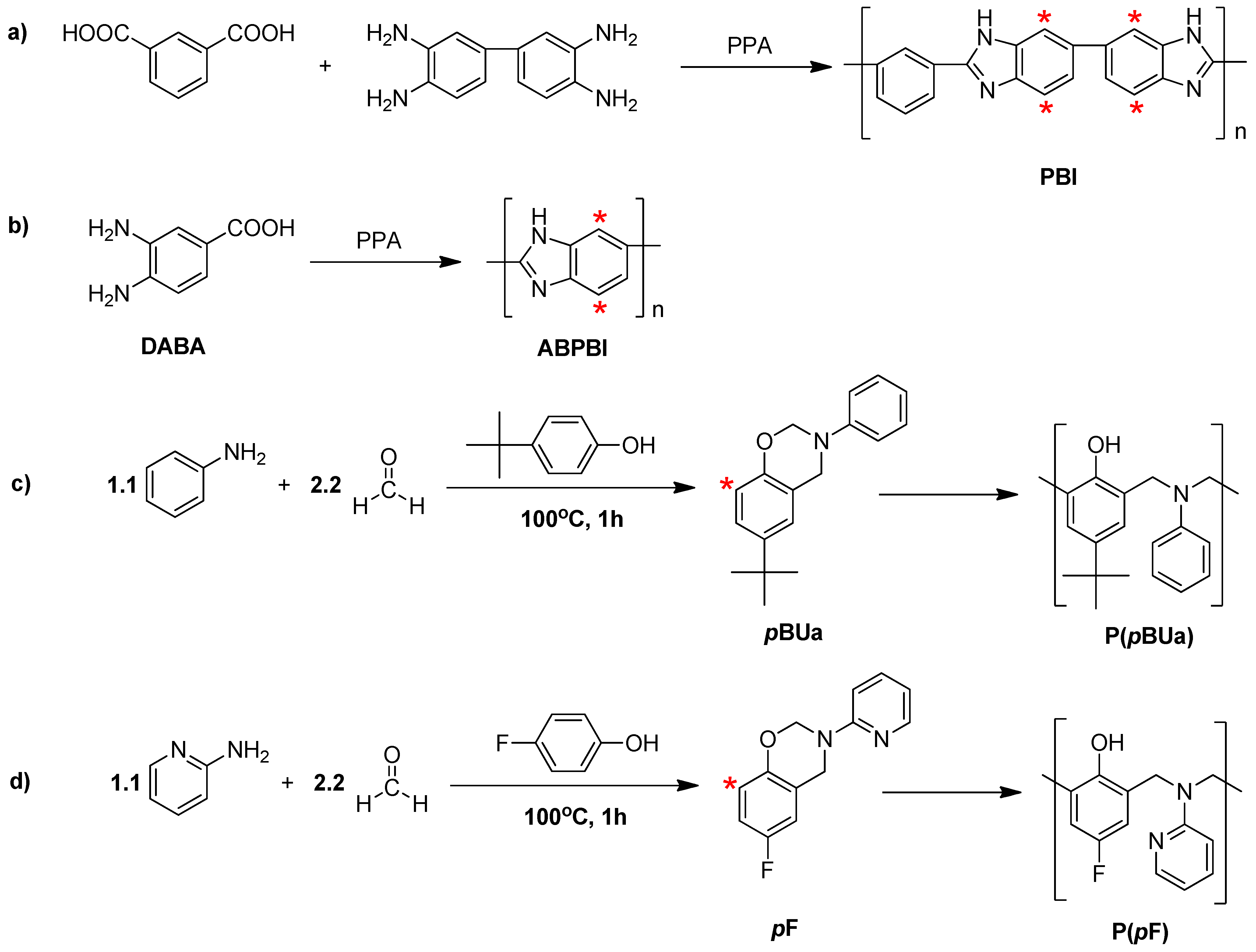
3.2.1. Synthesis of Benzoxazine Monomer, 6-tert-butyl-3-phenyl-3,4-dihydro-2H-benzo[e][1,3]oxazine (pBUa) and 6-Fluoro-3-(pyridine-2-yl)-3,4-dihydro-2H-benzo[e][1,3]oxazine (pF)

The synthesis of two representative benzoxazine monomers, pBUA and pF, is discussed in the literature with different reaction scales [84,85,86,87,88,89]. A small-scale reaction of less than 50g per batch with the solvent-less method invented by Ishida et al. [88] was applied for a higher conversion yield and with a short reaction time of less than 30 min. However, when the scale per batch exceeded 100 g, this methodology did not work properly due to difficult reaction control. Therefore, a normal synthetic procedure using an organic solvent was used instead [84,85,86,87,89]. Except for a pilot-scale monomer synthesis process, this type of solvent was applied to synthesize the corresponding functional BOA monomers used for material screening. More details about the stoichiometry, synthetic procedures, and purification technique, as well as a structural analysis are described in the literature [94,103].

3.2.2. Synthesis of Poly[2,2'-(m-phenylene)-5,5'-bibenzimidazole] (PBI)

PBI was synthesized by the condensation polymerization of 3,3'-diaminobenzidine (DABI) with isophthalic acid (IPA) in poly(phosphoric acid) (PPA) at 200 °C. The sequence of the experimental steps applied during this polymerization procedure is identical to that in the literature [94,104]. The following reaction scale is the basic composition for synthesizing various types of PBI derivatives for material screening. PPA (90.2 g) was added to a 250 mL three-necked reactor equipped with a mechanical stirrer, a nitrogen inlet, and a calcium chloride drying tube, and this was heated for 30 min at 150 °C. DABI (2.78 g, 13.0 mmol) and IPA (2.16 g, 13.0 mmol) were then added portion-wise, and the solution was stirred for 1 h at 150 °C to form a homogeneous solution under a slow nitrogen stream. The reaction temperature was raised to 200 °C under constant stirring for 30 min. Finally, phosphorous pentoxide (4.84 g, 17.0 mmol) was added and heated to 200 °C for 12 h under constant stirring using a mechanical stirrer. During this time, the reaction mixture became a very viscous dark-brown solution. The homogeneous solution was decanted into distilled water (800 mL) to isolate the polymer, and the precipitate was neutralized with an aqueous solution of NaHCO3 and rinsed several times with distilled water to remove the remnant PPA and phosphate salts. The precipitate was then dried overnight in a vacuum oven. The resulting polymer was ground using a pulverizer (A11 basic, IKA) and washed again to remove any residual phosphoric acid. Finally, the powder was dried at 70 °C in a vacuum oven for 3 days. Yield: >95%. FT-IR spectrum (KBr, cm−1): 3450–3250 (ν N–H), 1640 (ν C=N). 1H NMR chemical shifts (500 MHz, DMSO-d6, ppm): δ 9.14 (s, 1H), 8.32 (d, 2H), 8.00 (s, 2H), 7.81 (d, 2H), 7.62 (br, 3H).

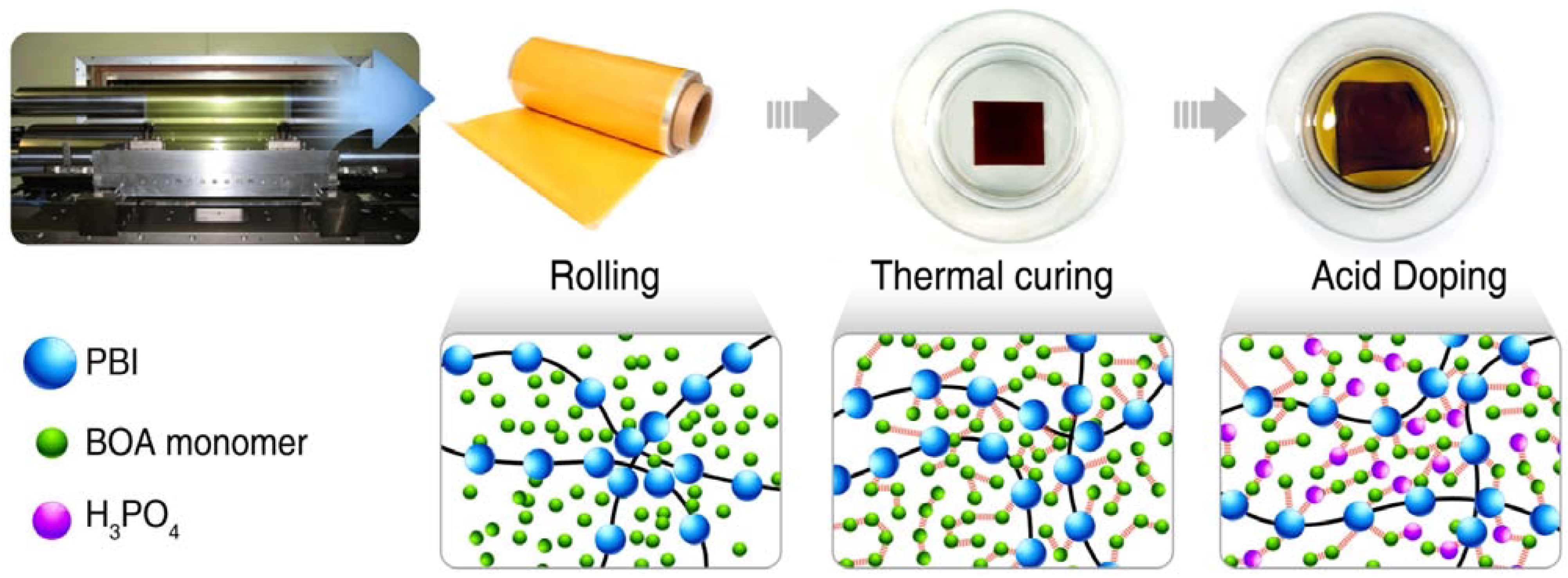
3.2.3. Preparation of the PA-Doped P(pBUa-co-BI) Membranes

P(pBUa-co-BI) membranes were prepared by reacting different weight ratios of pBUa to PBI by solution casting, followed by stepwise heating from 60 to 220 °C for 4 h and then maintaining the temperature for an hour. PA doping was achieved by immersing dried P(pBUa-co-BI) films in 80 to 85 wt % PA solution at 80 °C for 4 h. The details are given below.
The weight ratios of pBUa to PBI of 35, 50, and 65 are represented as P(pBUa-co-BI)-65, P(pBUa-co-BI)-50, and P(pBUa-co-BI)–35, respectively. The following procedure was used for the preparation of P(pBUa-co-PBI)-65. Other P(pBUa-co-BI) samples were prepared using the same procedure, except the weight ratios of pBUa to PBI differed. The polymer films were prepared using a solvent-casting technique. 5.00 g of PBI powder and 9.28 g of pBUa monomer were dissolved in 128 g of a DMAc solution at 80 °C for 4 h. The blended solution was then spread onto a clean flat glass plate or polyethylene terephthalate (PET) film. The thickness of the solution was controlled using an adjustable doctor blade, and the thermal treatment of the blended solution followed. The casted solution was heated stepwise from 60 to 220 °C for 4 h in a convection oven until no DMAc evaporation was noted. After cooling to room temperature slowly, the obtained brown film was soaked in distilled water and peeled from the substrate. The resulting film was dried at room temperature under a vacuum for 2 days. The thickness of the dried films ranged from 30 to 50 μm. We found that the variation of the polymer film thickness in this range does not affect the proton conductivity if the films have same acid doping levels. To enable the membrane to conduct protons, the dried films were immersed in an 85 wt % PA solution at 80 °C for 4 h. The PA-doped membranes were taken out of the PA solution and then blotted with filter paper. They were then dried at 70 °C under a vacuum for 2 days and weighed again (W1). The PA within the membranes was intentionally removed by rinsing with an aqueous solution of NaHCO3 and distilled water several times in order to measure the PA content. The films were then dried for 2 days in a vacuum oven and weighed (W2). The weight difference, (W1W2), was assumed to be the weight of the absorbed PA. The PA content of the membrane was then calculated as the weight percent (wt %) of PA absorbed in the membrane using Equation (4).
PA content (wt %) = (W1W2)/W1 × 100

3.2.4. Preparation of PA-Doped PpF-co-ABPBI

PpF-co-ABPBIs were also prepared by reacting different weight ratios of pF to ABPBI. The sequence of the experimental steps for PpF-ABPBI-50 applied during this polymerization procedure is described as follows. A 250 mL three-necked reactor equipped with a mechanical stirrer, a nitrogen inlet, and a calcium chloride drying tube was charged with 57.0 g of PPA and heated for 30 min at 150 °C. Into this reactor, purified DABA (3.93 g, 25.8 mmol) was added portion-wise and the solution was then stirred for 30 min at 150 °C under a slow stream of nitrogen. After that, the reaction temperature was raised to 220 °C and the solution was stirred for 2 h. The reaction mixture became a very viscous dark-brown solution. In this solution, 150 g of o-phosphoric acid was added to adjust the viscosity, and stirring then continued for 6 h. The reaction temperature was lowered to 120 °C, and pF (3.00 g, 13.9 mmol) was added to the solution. The mixing was continued for 6 h until the solution became homogeneous. During the mixing process, the solution turned dark in color. The same procedure was followed to produce pF-ABPBI-65 and 35 with different compositions.
PpF-co-ABPBI membranes were prepared via a direct casting method. A 40 g of pF-ABPBI solution was spread onto a clean flat glass plate of 20 × 20 cm2. The thickness of the solution was controlled using an adjustable doctor blade. The casted solution was heated gradually from 100 to 220 °C for 4 h under a nitrogen atmosphere and this temperature was sustained for an hour. After a thermal treatment, the casted solution was cooled to room temperature slowly in an oven. The obtained dark-brown films were immersed in PA solutions containing various concentrations of PA at 30 °C for a day. The PA-doped membranes were removed from the PA solution and then blotted with filter paper. The PA-doped membranes were dried at 30 °C under vacuum for 2 days. The dried membranes were cut to a size of 2 × 2 cm2 in order to measure the PA content, after which the squares were weighed (W1). The PA within a piece of the membrane was intentionally removed by rinsing with an aqueous solution of NaHCO3 and distilled water several times. The films were then dried for 2 days in a vacuum oven and weighed (W2). The PA content of the membrane was then calculated using Equation (4). PA-doped ABPBI and PBI membranes were also prepared by a commonly used solution-casting method [68,104].

3.2.5. Preparation of Membrane-Electrode Assembly (MEA)

The slurry for forming the catalyst layer was prepared by adding catalyst powder into a PVDF solution in N-methyl-2-pyrrolidone (NMP). After the slurry was spread onto waterproof carbon evenly by means of an automated doctor blade technique, the electrode catalyst layer was dried at 120 °C for 2 h in a ventilated oven. Each electrode catalyst layer consisted of PtCo alloy supported on carbon (Tanaka Kikinzoku Kogyo, TEC36E52) and PVDF on the cathode and PtRu supported on carbon (Tanaka Kikinzoku Kogyo, TEC61E54) and PVDF on the anode. The mean platinum loading of the catalyst layer were 0.9 mg cm−2 on the anode and 1.7 mg cm−2 on the cathode. The PA-doped membrane was mounted on a single cell and the electrodes and membrane without a preceding hot-pressing step were assembled in a lab-made single cell with graphite bipolar plates and gold-plated copper end plates. The active area in the MEA was about 7.84 or 25 cm2; the assembling torque was 3 N m with eight M6 bolts. The MEA was operated at 150 °C with hydrogen as a fuel and air without humidification at ambient pressure and at a flow rate of 100 and 250 cc min−1 in each case.

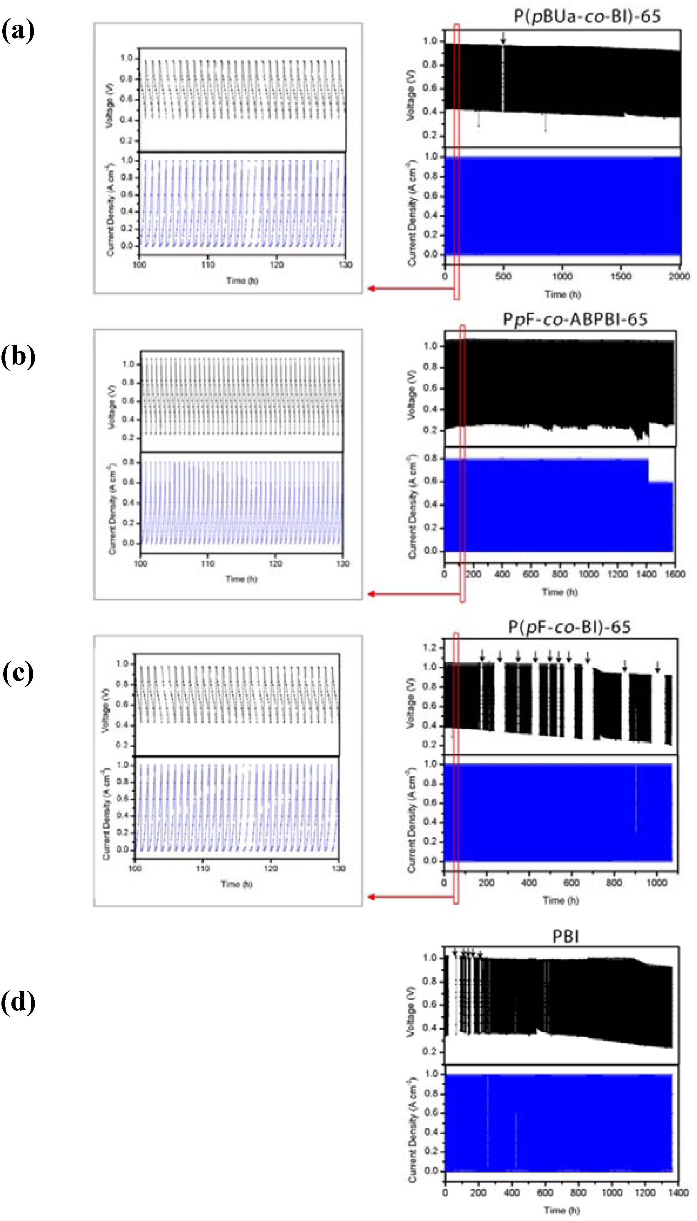
3.2.6. Cell Performance Measurement and Acceleration Lifetime Test (ALT)

The cell performance tests and in situ ALT were executed on a Hizen custom-made fuel cell test station. Unit cells were operated at 150 °C with hydrogen at 100 cc min−1 and air at 250 cc min−1 without humidification at ambient pressure. During the in situ ALT, the cells were exposed to repetitive load cycling. The current density was increased stepwise from zero to 1.0 A cm−2 for 1 h, and then recovered to zero. This type of cycling was repeated until the open circuit voltage (OCV) dropped below 0.9 V.

3.3. Characterization

Details pertaining to the characterization of the prepared membranes, including the inherent viscosity, 1H and 13C NMR, FT-IR, TGA, DSC, mechanical properties, and electrochemical analysis are well explained in the literature [90,91,92,93,94,103]. In this review, the representative effects resulted from the new type of copolymerization via cross-linking between a thermoplastic polymer and a thermosetting resin. In particular, evidence of copolymer formation, chemical stability and viable cell performance of the prepared membranes will be shown.

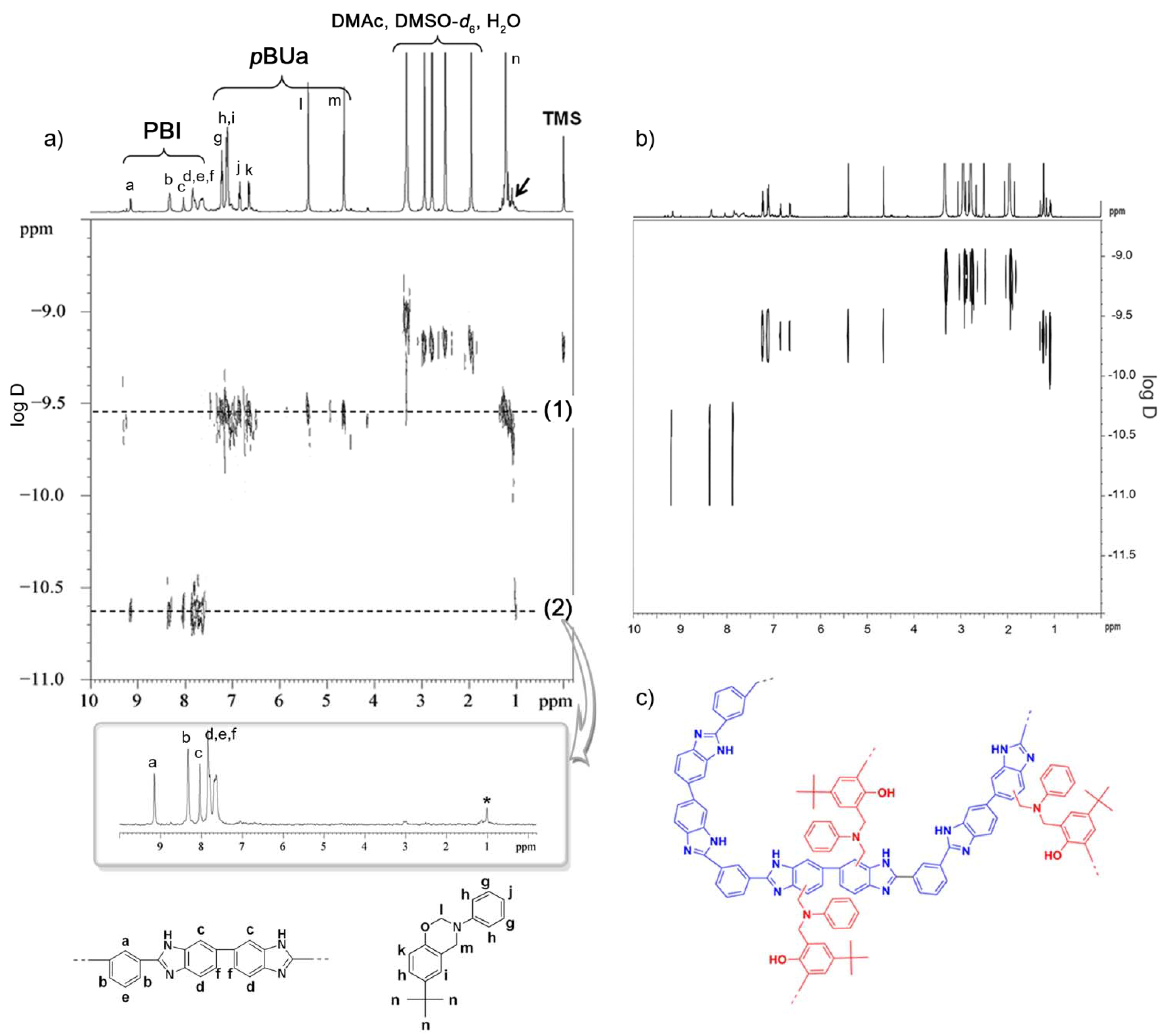
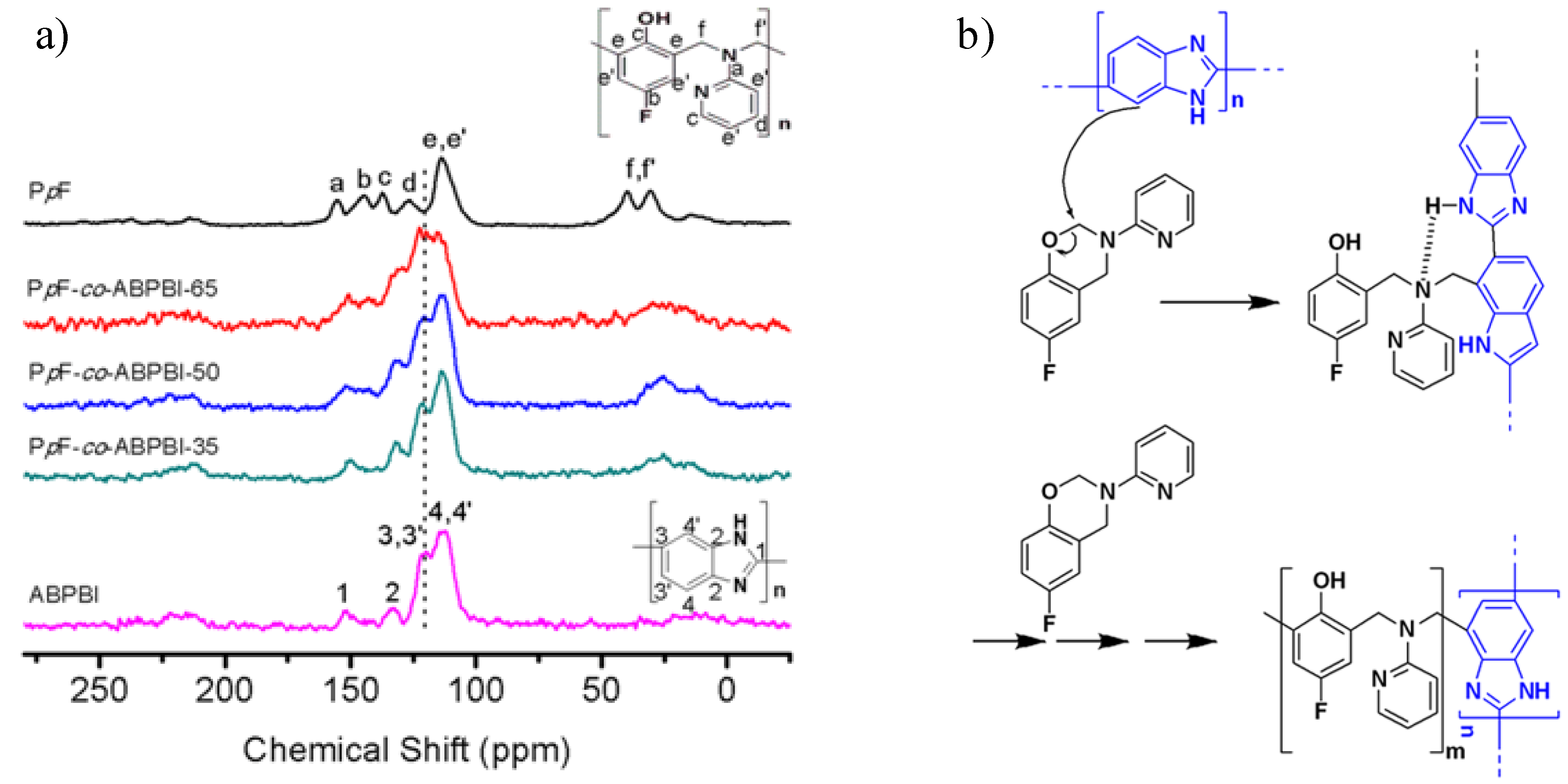
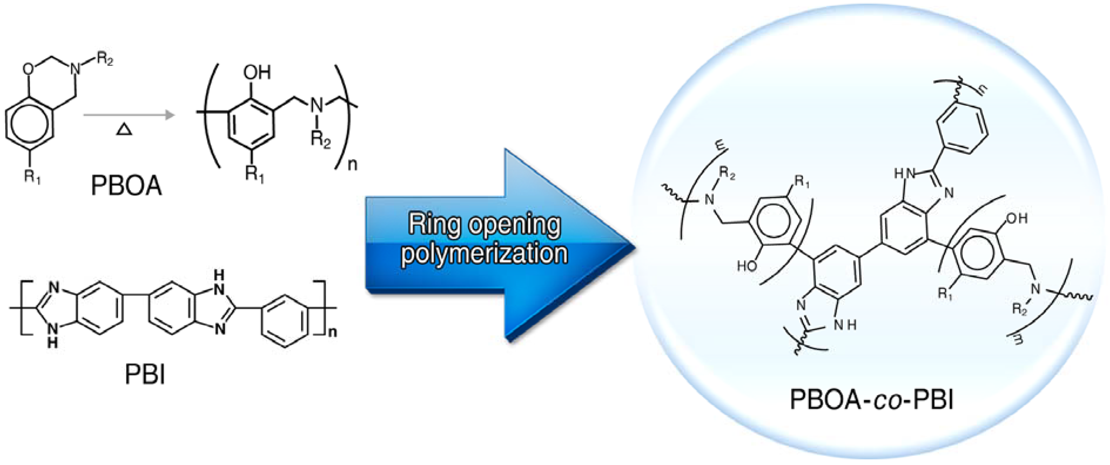
3.3.1. Copolymer Formation

The formation of cross-linked copolymeric structures of pBUa and PBI during the casting process was confirmed by 2D diffusion ordered spectroscopy (DOSY) NMR and the likelihood of an unexpected reaction between pBUa and PBI was investigated. Figure 4a shows a spectrum obtained after heating at 140 °C for 30 min. Due to the intractable nature of the fully reacted blends, the analysis was undertaken at the initial stage of the reaction mixing, where the solubility of the reactants and the reaction products could be determined. DOSY NMR can classify the spectrum of each ingredient according to the differences in the hydrodynamic volumes (or diffusion coefficients) of the ingredients which are melted into the solution. This process is especially well known for having the advantage of classifying blended mixtures existing in a solution without any special preliminary treatment [105,106,107,108,109,110]. Theoretically, the same element size of a molecule connected by a combined reaction in the DOSY NMR spectrum appears on the same line of the y-axis. Therefore, as shown well in Figure 4a, the signals created by the solvents, including water, DMSO and DMAc, have much smaller molecule sizes of around −9.0 to −9.2 on the y-axis, while the pBUa monomer, which does not start the polymerization reaction, appears on the same line of (1) between −9.5 and −9.6. On the other hand, the signals resulting from PBI appear at about −10.6. This position is much smaller than that of the pBUa monomer. According to the principal of DOSY-NMR, the y-axis coefficient, related to the diffusion coefficient, decreases as the size of the molecule increases. Therefore, it is feasible for PBI, which is a polymer, to have a higher negative value than pBUa, which is a single molecule. Surprisingly, the DOSY spectrum revealed that the tertiary butyl moiety (marked by the asterisk) of pBUa was positioned on the same line as the PBI (dotted line (2) in Figure 4a) even at the very beginning of the polymerization reaction. Because the translational diffusion coefficients of all protons belonging to a single molecule become identical, the NMR signals from each component in a mixture appear parallel to the x-axis and are separated by each component on the y-axis. Thus, this provides decisive evidence of the invention of the new copolymer proposed in this paper that the pBUa covalently combines in the PBI. The separate 1D slice spectrum clearly shows the tert-butyl protons at 1.0 ppm (marked by an asterisk in inset) in the slightly up-field region, which has never been observed in a PBI homopolymer or in P(pBUa) homopolymers. Therefore, we can conclude that a small quantity of pBUa is directly attached to the PBI backbone, perhaps via covalent bonds, even at the initial stage of the polymerization reaction such that the covalent bonds between the two polymers improve the durability. The chain propagation of BOA is preceded by the reaction between the unobstructed ortho position of the benzene ring and the BOA, as previously mentioned. The PBI (or ABPBI) also has an unobstructed ortho position of the benzene ring (the asterisks in the PBI and ABPBI in Figure 1a,b, respectively). From these results, we assumed that the carbon marked by the asterisk on the benzene ring in the P(pBUa) bonded covalently with the unobstructed ortho position of the benzene ring in PBI (or ABPBI), making it possibly a covalent-linked structure.
Figure 4. 2D diffusion ordered spectroscopy (DOSY) NMR spectra of (a) pBUa and PBI mixture (pBUa:PBI = 65:35 (wt %)) obtained at 140 °C for 30 min, (inset) 1D slice 1H NMR spectrum at ca. −10.6 ppm; and (b) mixture of pBUa obtained at 140 °C for 1 h and PBI (pBUa: PBI = 65:35 (wt %));(c) Possible chemical structure of P(pBUa-co-BI)s [94].
Polymers 05 00077 g004
Other possible aromatic proton signals from P(pBUa) homopolymers (6.0 to 7.7 ppm) are not clearly observed in the inset in Figure 4a. The tert-butyl group, with nine protons, is located at the side chain and thus a greater signal intensity level is expected, while other aromatic groups located in the polymer backbone have only one or two protons. As a result, their proton signal intensity levels should be much smaller or may be overlapped with those of PBI [111]. The tert-butyl signals at ca. −10.6 ppm on the y-axis were confirmed to be caused by the copolymeric structures in separate 2D DOSY NMR experiments. The P(pBUa) homopolymer was intentionally prepared by heating the pBUa monomer at 140 °C for 60 min. It was mixed with PBI homopolymer at a 65 to 35 weight ratio and 2D DOSY NMR measurements were taken (Figure 4b). In the separate NMR spectra, signals from tert-butyl protons at 1.0 ppm are not observed at ca. −10.6 ppm on the y-axis, where the PBI signals appear. Therefore, we believe that the P(pBUa) signal at ca. −10.6 ppm on the y-axis is due to covalently bonded copolymeric structures of the PBI and P(pBUa) moieties.
The formation of cross-linked structures was further confirmed from chemical stability experiments, which are discussed later in this paper. The polymerization of benzoxazine is known to proceed through reaction of the unobstructed ortho position of the benzene ring (the asterisk in pBUa, Figure 1c) with the methylene group between oxygen and nitrogen on the oxazine ring [66]. PBI also has four carbons at the unobstructed ortho position of the benzene ring (the asterisk in PBI, Figure 1a). In this case, the reactivity should be close to or exceed that of the benzoxazine due to the electron-withdrawing imidazole groups [112,113]. Therefore, we assumed that the peripheries of the carbons (marked by the asterisk in Figure 1a) of the benzene rings in the PBI could covalently react with the methylene groups of pBUa (Figure 4c).
We also confirmed the chemical structures of the PBOA-co-ABPBI membranes, especially PpF-co-ABPBI, by 13C CP MAS solid-state NMR spectroscopy. Shown in Figure 5, P(pF) and ABPBI are well assigned, respectively.
Figure 5. (a) Solid-state cross-polarization/magic angle spinning 13C NMR spectra; and (b) possible reaction between pF and ABPBI forming the cross-linked PpF-co-ABPBIs [103].
Polymers 05 00077 g005
In the case of PpF-co-ABPBI, the peak at around 120 ppm increased with an increase in the content of P(pF); however, this was not observed in the P(pF) homopolymer. It is speculated that the “e” carbon of the benzene ring in P(pF) bonded covalently with the unobstructed ortho position of the benzene ring in ABPBI, making it possible to form covalent bonds. These results were in good agreement with the DOSY NMR obtained results of the P(pBUa-co-BI). Also, we proposed a possible reaction between pF and ABPBI resulting in cross-linked PpF-co-ABPBI, as shown in Figure 5b.
Combining these analytical results, we expect that the characteristic behavior of this new type of polymeric product results from hybridization between the thermosetting and thermoplastic polymers rather than that of a simple polymer mixture. Building on these findings, we prudently propose a plausible reaction mechanism between PBOA and PBI (or ABPBI) in Figure 5b, when a cured BOA monomer with PBI (or ABPBI) is used. In more detail, there was no former example or precedent which can explain such a structure in one word. To the best of our knowledge, there is no scientific terminology which can describe this type of polymer; that is, it is a blended mixture of thermosetting and thermoplastic polymers and their copolymers at the same time based on the IPN concept.

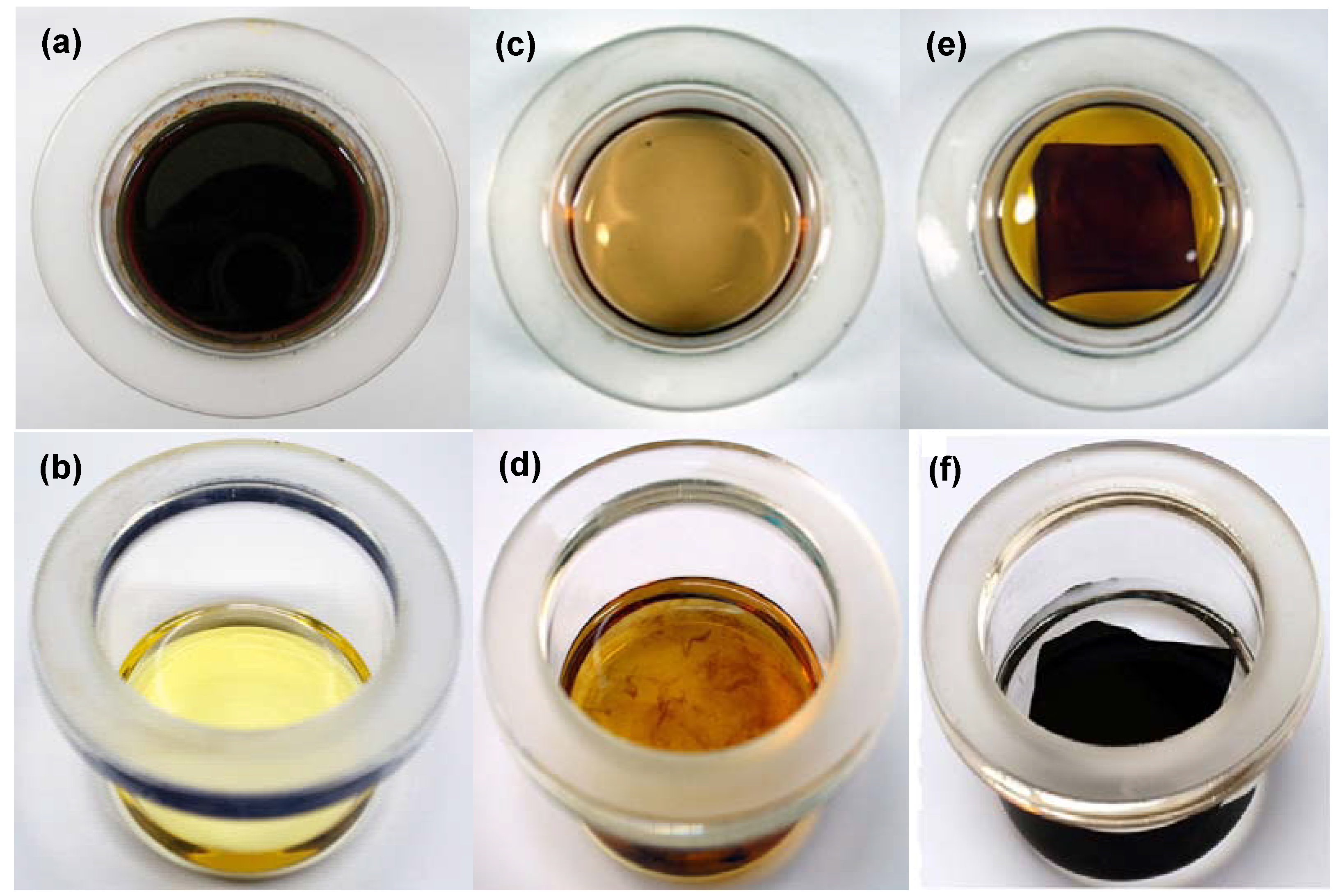
3.3.2. Chemical Stability

Figure 6 shows the (a), (b) PBOAs, (c), (d) PBI and ABPBI, and (e), (f) P(pBUa–co–BI)-65 and PpF-co-ABPBI-65 membranes after being immersed in an 85 wt % PA solution at 160 °C for 1 h. The PBOAs and PBI (or ABPBI) membranes were completely soluble; however, the shape of PBOA-PBI (or ABPBI) was maintained during the test due to the incorporation of PBOAs with PBI (or ABPBI). Especially in the case of the PpF-co-ABPBI-65 membrane, no trace of the extract was observed. From the PBOAs dissolved completely even at a relatively low concentration of the PA solution, at approximately 60 wt % at room temperature, the part dissolved out in Figure 6e was thought to be the related PBOA which had not reacted with PBI (or ABPBI). It is noteworthy that PBOA-co-PBI (or ABPBI) membranes fabricated by these two materials, PBOAs and PBI (or ABPBI), which have a poor chemical stability in a PA solution, showed improved chemical stability under the same testing conditions.
Figure 6. Chemical stability of (a) P(pBUa); (b) PpF; (c) PBI; (d) ABPBI; (e) P(pBUa-co-BI)-65; and (f) PpF-co-ABPBI membranes after being immersed in an 85 wt % PA solution at 160 °C for 1h.
Polymers 05 00077 g006
In fact, the chemical stability of PBOA-co-PBI (or ABPBI) membranes in a concentrated PA solution increased with an increase in the PBOA moiety in the membranes. These exceptional properties of PBOA-co-PBI (or ABPBI) membranes demonstrate that this simple strategy of the semi-IPN of PBI with a thermosetting resin is quite effective to improve both the chemical stability and the solubility of PBI in concentrated PA at high temperatures without sacrificing the mechanical or thermo-oxidative stabilities. The PA contents in the PBOA-co-PBI membranes after being immersed in 85 wt % PA solution for 4 h were greater than 83 wt %. 4 h at 80 °C was found to be sufficient to obtain the maximum PA content, as further immersion did not increase the PA content any further [114]. Considering that the PA content of the PBI membrane was approximately 81 wt %, the basic functional groups of PBOA, such as the hydroxyl, tert-amine, tert-butyl, and pyridinyl groups, had to contribute to the acid-base interaction with the PA [115], resulting in the realization of a high PA uptake of PBOA-co-PBI (or ABPBI) (Table 1).
Table 1. Proton conductivity of phosphoric acid (PA)-doped polybenzoxazine (PBOA)-co-PBI (or ABPBI) membranes at 150 °C under un-humidified conditions.
MembranesPA content (wt %)Proton Conductivity (S cm−1)
P(pBUa-co-BI)-6588.50.1206
P(pBUa-co-BI)-5083.90.0922
P(pBUa-co-BI)-3583.00.0792
P(pF-co-BI)-6586.60.1267
P(pF-co-BI)-5084.90.1327
P(pF-co-BI)-3583.00.1091
PpF-co-ABPBI-6573.00.1015
77.10.1472
PpF-co-ABPBI-5074.40.0983
78.30.1098
81.00.1315
84.40.1434
PpF-co-ABPBI-3571.90.0656
75.60.0889
84.10.1449
ABPBI a75.3 b0.0832
PBI a81.2 b0.0951
a Cast from solution casting; b Maximum PA content possible for the membranes, in each case.
Although an increase in the PA content guarantees high proton conductivity, it also results in the deterioration of the mechanical properties [7,60,115,116]. As shown in Table 2, the tensile strength of the membranes decreased with an increase in the content of PBOA with a similar PA content. Nonetheless, it is clear that the PBOA-co-PBI (or ABPBI) membranes could absorb a greater amount of PA with a mechanical strength sufficient to prepare free-standing films. Considering that thermosetting resins such as PBOA normally exhibit some degree of elongation upon a break, this novel material must be quite different from ordinary thermosetting polymers. Its highly ductile nature with high thermal resistance is unusual and attractive considering the high thermosetting resin content of this membrane.
Table 2. Mechanical properties of the membranes.
MembranesPA content (wt %)Tensile strength (MPa)Elongation at break (%)Modulus (MPa)
P(pBUa-co-BI)-6588.52.1972.35.70
P(pBUa-co-BI)-5083.92.6954.814.5
P(pBUa-co-BI)-3583.04.2538.141.4
PpF-co-ABPBI-6562.824.548.934.8
72.911.573.917.1
PpF-co-ABPBI-5076.614.970.621.4
79.313.411311.2
PpF-co-ABPBI-3567.125.448.547.2
77.418.178.925.3
82.511.161.523.3
ABPBI a67.139.5247260
PBI a76.819.514325.1
81.25.3447.643.2
a Cast from solution casting.

3.3.3. The Proton Conductivity

The proton conductivity of PBOA-co-PBI (or ABPBI) membranes with different PA contents was measured as a function of the temperature (100 ~ 160 °C) under anhydrous conditions (Table 1). The proton conductivity increased with an increase in the temperature and PA content. As listed in Table 1, the proton conductivity at 150 °C under anhydrous conditions is linearly related to with the PBOA content, finally exceeding 0.12 S·cm−1 and exhibited a higher value than that of a membrane with PBI or ABPBI only under similar conditions. This implies that functional groups of PBOA such as hydroxyl, tert-amine, tert-butyl, and pyridinyl groups simultaneously contribute to proton transport in conjunction with the typical proton transport mechanism of PA-doped PBI membranes induced by the acid–base interaction.

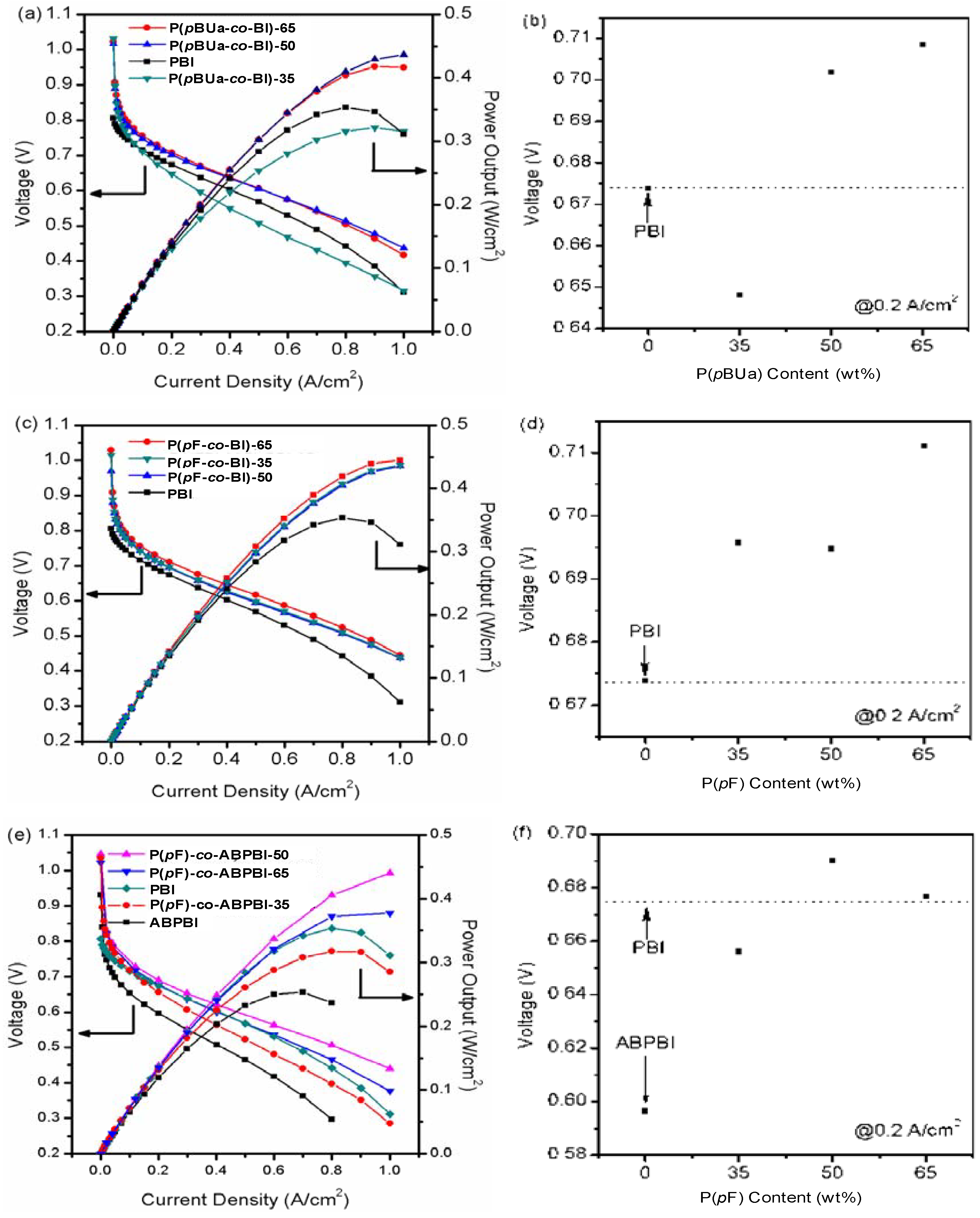
3.3.4. Fuel Cell Evaluation

Preliminary fuel cell evaluations were performed on PA-doped PBOA-co-PBI (or ABPBI) membranes with thicknesses of approximately 50 µm (PBI) and 200 µm (ABPBI) after PA impregnation. PA-doped PBOA-co-PBI (or ABPBI) membranes can be successfully used to manage fuel cell temperatures in the range of 120 ~ 180 °C without any external humidification or pressure requirements. The operating voltages and power densities of PBOA-co-PBI (or ABPBI) were observed to be enhanced relative to those of the PBI and ABPBI membranes at the same current density (Figure 7). Surprisingly, the cell voltage of the PpF-co-ABPBI-50 membrane increased by about 0.1 V at 0.2 A cm−2 compared to that of the ABPBI sample. The proton conductivities and PA contents of the membranes are, undoubtedly, important factors in determining the fuel cell performance. It appears, however, that no direct relationship exists between the conductivity and performance, as the fuel cell performance of a membrane may be affected by other limiting factors. To elucidate the relationship between the proton conductivity and the fuel cell performance in detail, more work is being pursued.
Figure 7. (a), (c), and (e): Polarization and power density curves of PA-doped membranes; (b), (d), and (f): Cell voltage with the BOA content at 0.2 Acm−2, 150 °C, non-humidified H2 and air, cathode; 0.9 mgcm−2 PtRu loading, anode; 1.7 mgcm−2 PtCo loading.
Polymers 05 00077 g007
Recently, considerable research on the durability of PEMs has been conducted so that they may be used more widely. However, these durability studies remain in their infancy due to the scarcity of PEMs showing feasible physicochemical properties. In addition, evaluations of the durability involve difficult and time-consuming process. The in situ acceleration lifetime test (ALT) has been shown to be a reliable method to predict the durability of PEMs effectively during the actual operating conditions of a fuel cell over time [117,118,119]. In this study, more severe operating conditions of the dynamic mode (load changing test cycle) were employed to accelerate the degradation of the membrane by 30 times compared to normal fuel cell operating conditions. The attenuation of the OCV below 0.9 V implies the evolution of the microstructure of the membrane; this was considered to be an ALT screening criterion before the failure of the membranes caused by mechanical damage, such as membrane thinning or pinhole formation [117].
Figure 8. In situ acceleration lifetime test (ALT) of (a) P(pBUa-co-BI)-65;(b) PpF-co-ABPBI-65;(c) P(pF-co-BI)-65 and (d) PBI membranes at 150 °C, in non-humidified H2 and air, cathode; 0.9 mgcm−2 PtRu loading, anode; 1.7 mgcm−2 PtCo loading. The active area is 7.84 cm2. Downward arrows (0.9in the figure denote the regions induced by temporary recording errors.
Polymers 05 00077 g008
The ALT measurements remained persistently above 600 h for the PBOA-co-PBI (or ABPBI)-65 membranes. Interestingly, the PpF-co-ABPBI-65 membrane showed remarkably sustainability of 1500 h at 150 °C in the ALT mode (Figure 8), corresponding to an expected lifetime greater than 47,560 h. The lifetime loss of the PpF-co-ABPBI-65 membrane in the ALT mode was calculated based on both the maximum OCV value, 1.068 V, and the run time while measuring its OCV, ~5670 h (~189 h on ALT mode), at a rate of −0.42 µV h−1 until failing at ~47530 h (~1584 in the ALT mode).
In an attempt to support our ALT results, a steady-state lifetime test of PpF-co-ABPBI membranes with an active area of 25 cm2 was done under real operating conditions at 150 °C and with a constant current (0.2 A cm−2) over time.
Considering that the required lifetime of PEMFCs for transportation and stationary applications is greater than 5000 h and 40,000 h, respectively [49], it is noteworthy that the long-term operation of PBOA-co-PBI (or ABPBI) membranes, exceeding 40,000 h with a large amount of PA at a high temperature was realized by incorporating the merits of thermosetting resins into the well-known acid-base complex polymer membrane via semi-IPN technology.
Finally, to demonstrate how easy it is to apply this process to large-scale production, we applied the blended solution of PBI with monomers of PBOA to a conventional die coating machine. Figure 9 shows that this new material can be readily applied to large-scale production, such as the continuous manufacturing of 30 cm × 140 m polymer film. Also, a schematic diagram of molecular interactions at each step was proposed.
Figure 9. Large-scale (30 cm × 140 m) P(pBUa-co-BI)-65 film using a conventional die coating machine (the picture on top left) and corresponding possible chemical structures (the picture on the bottom in the order of reaction steps) before (left) and after (right) heating at 220 °C and after acid doping
Polymers 05 00077 g009

4. High Temperature MEA

4.1. MEA Design and Characteristics

The high-temperature PEMFC operates at temperatures between 150 and 180 °C without external humidifiers. Phosphoric acid is used as the proton conducting medium in the electrolyte and catalyst layer. Figure 10 shows the cross-section scheme of the MEA. The H2 fuel gas flows into the anode, where it undergoes an oxidation reaction at the Pt catalyst. The H+ proton then travels through the phosphoric-acid-doped membrane and reaches the cathode side, where it reacts with oxygen to produce water. The phosphoric acid, which partially fills the catalyst layers, provides a path for H+ in the electrodes. Owing to its high operation temperature, the water exits the MEA as a vapor. The high operation temperature enables the design of the MEA, the stack and the fuel cell system to be simplified. Water management is necessary in the MEA, which operates at a temperature under 80 °C, because the water produced from the oxygen reduction at the cathode remains in the cathode as liquid water. If the water accumulates in the cathode, the pores are filled with water, which blocks the diffusion path for the reactant gases. Such phenomena can cause a sudden failure of the MEA. Thus, the high-temperature PEMFC is much unlikely to fail due to water flooding in the electrode structures. However, it is necessary to distribute the phosphoric acid in the electrodes so that the pores which are necessary for the reactant gases to be supplied to the catalyst sites are sufficiently present in the catalyst layer.
Figure 10. Cross-section scheme of the high-temperature PEMFC MEA.
Polymers 05 00077 g010
As mentioned in the previous section, one example of a high-temperature PEMFC utilizes phosphoric-acid-doped PBI as its polymer electrolyte [4,7,69]. Concentrated phosphoric acid offers thermal stability and high proton conductivity at temperatures between 150 °C and 200 °C. However, the slow oxygen reduction of Pt [120] and the low oxygen solubility in phosphoric acid [121] limit the cell performance of the high-temperature PEMFC. To achieve the performance requirements, it is essential to overcome the barriers that are imposed when using phosphoric acid as the proton-conducting medium. The largest overpotential during the operation of a high-temperature PEMFC MEA is known to be the kinetic overpotential in the cathode, which is caused by the slow ORR of Pt in the presence of phosphoric acid. The low oxygen solubility and high ORR Tafel slope of 120 mV decade−1 in phosphoric acid along with the anion adsorption of H3PO4 on Pt [122] are reported to slow the ORR of the Pt in the cathode. Attempts have been made to improve the oxygen reduction kinetics of Pt by adding a perfluorinated compound to phosphoric acid [121,123]. It was also reported that the addition of perfluorinated compounds increased the solubility and diffusivity of oxygen in phosphoric acid and improved the oxygen reduction kinetics in the cathode [123]. Alternative fluorocarbon acid electrolytes were also used as a replacement for phosphoric acid in an attempt to improve the oxygen reduction rates of Pt [124].
Binders and the presence of certain polymers in electrodes were found to enhance the performance of fuel cells by increasing the rate of Pt utilization and the cell performance [8]. For the fuel cell that used the phosphoric-acid-doped PBI electrolyte, the amount of PBI in the catalyst layer was found to affect the cell performance [124]. This suggests that the PBI in the catalyst layer absorbed phosphoric acid and provided a path for protons. An excess amount of PBI hindered gas permeability in the catalyst layer and lowered the cell performance [125]. Other reports investigated the ORR at the interface of PBI film and Pt [126,127] and found that the PBI film on Pt did not change the oxygen reduction kinetic parameters, such as the reaction order with respect to O2, the Tafel slope or the exchange current density in a 0.1 M H3PO4 solution at 25 °C [126]. When phosphoric-acid-doped PBI was used as the electrolyte at an elevated temperature, it was also concluded that the acid doping level did not influence the oxygen reduction mechanism at the Pt and PBI- H3PO4 interface [127].
Although many attempts have been made to overcome the cell voltage limitations imposed when using phosphoric acid as the proton-conducting medium, the cell voltage of the high-temperature PEMFC MEA remains much lower than the cell voltage measured with a Nafion-based MEA. However, because the simpler system designs of high-temperature PEMFC systems offer advantages over low-temperature PEMFC systems, they are marketed in residential and portable power applications, and optimization of their system components is therefore necessary.

4.2. MEA Performance on System Level Requirements

The challenge of a high-temperature PEMFC MEA is to maintain its membrane and catalyst properties at an operation temperature between 150 °C and 180 °C. In order to achieve the lifetime requirement, the MEA needs to be able to maintain the its reaction sites, retain its ability to transfer protons through the membrane as well as in the catalyst layer, and maintain its pore distribution in the electrodes for gas diffusion during cell operation under harsh conditions. The MEA in the fuel cell is compressed to maintain good contact with the bipolar plate. The thickness of the MEA is reduced from 20% to 40% depending on the design of the MEA. Under such conditions, it is essential that the membrane and the electrode materials maintain their mechanical strength. When the structure of the MEA materials fails in the compressed state, the MEA can no longer maintain contact with the bipolar plate and the electrical circuit therefore fails. The loss of mechanical strength of the material also indicates that they no can longer maintain the role of proton conduction, providing sites for reactions and a path for gas diffusion.
High-temperature PEMFC systems are considered to be candidates for residential and portable power applications. The residential systems require the MEA to operate for over 40,000 h of continuous operation. The MEAs also need to be able to operate in a start-stop mode of operation. In order for researchers to achieve these requirements, it is necessary for them to understand the mechanisms of cell voltage decay in a high-temperature PEMFC MEA. A commercial PBI-based MEA was reported to operate for 18,000 in continuous operation mode [95], and the MEA was then improved with an increased lifetime during the start and stop mode of operation [128]. During the start and stop mode of operation, the MEA undergoes temperature cycling, potential cycling and humidity changes inside. With these variations in the temperature, potential, and humidity, the catalyst and membrane are exposed to changes that accelerate their degradation. Catalysts are exposed to high open-circuit potentials, and membranes are exposed to the thermal cycling which can damage their mechanical stability. The degradation of the MEA components leads to faster cell voltage decay during start–stop operations, as shown in Figure 11.
Figure 11. MEA lifetime. Continuous and start–stop mode operation, 150 °C, start–stop operation: operation for 2 h and stopped for 40 min.
Polymers 05 00077 g011
In high-temperature PEMFC systems, the H2 fuel is produced by reforming methane-containing gases. The product of such a reformed gas contains CO, CO2 and water. The CO content can be 1% to 5%, while the CO2 content is between 15% and 20%. Thus, a high-temperature PEMFC MEA needs to have high tolerance to CO gases to achieve the desired level of cell performance in high-temperature PEMFC systems.
The cost of the MEA is another issue that needs to be resolved before the high-temperature PEMFC system can be widely applied in the field. On account of the low cell performance, the Pt content in the MEA is 3 to 5 times higher than the Pt amounts used in an MEA with Nafion as the electrolyte and ionomer [96,103]. On account of its Pt catalyst content, the cost of a high-temperature PEMFC MEA is higher than that of a low temperature PEMFC MEA. The Pt loading of a high-temperature PEMFC MEA needs to be lowered to the level that the price of the high-temperature system to establish price competitiveness in the fuel cell market.

5. Summary and Further Studies

In summary, we developed new PEMs via an unconventional approach that involved combining a thermosetting resin with a thermoplastic polymer, showing unprecedented results. Also, the methodology of achieving a corresponding membrane could be the foundation of cost-effectiveness and may guarantee both long-term durability and proton conductivity. Because one of the advantages of benzoxazine is its excellent molecular design flexibility for monomers, our approach as described here could be extended to various synthetic designs of benzoxazine monomers, including di- or tri-functional benzoxazine moieties, thereby enabling membrane fabrication with PBI or ABPBI membranes. These studies highlight the great feasibility of benzoxazine as a PEM. In addition, Figure 12 shows a new concept of copolymer formation, which is the first example engrafting a thermosetting resin into a thermoplastic polymer. The technical superiority of this method has already been applied and verified by a leading chemical company, BASF [129], resulting in a membrane lifetime that shows a threefold increase. Integrating all of the aforementioned results, the proposed hybridized copolymeric membrane can provide a new opportunity in the stagnant fuel cell market and can contribute to earlier commercialization while also having an economical ripple effect.
Figure 12. PBOA-co-PBI formation and proposed cross-linked copolymer structure.
Polymers 05 00077 g012
Although we established a new concept of a copolymer system that can play a pioneering role in high-temperature PEMFCs when applied to fuel cells and components in general—including a membrane, an electrode additive, a binder and even a bipolar plate—enhancing the process for copolymerization is still necessary. Currently, copolymerization is being performed by a thermal curing process without an initiator or accelerator. However, the curing temperature of PBOA as applied in this study is fairly high, at over 200 °C, and at least a couple of hours are necessary to obtain structural solidification. This fact lowers the pilot-scale production of the MEA despite its unprecedented durability in high-temperature applications. In parallel with improving the processability, we also continue to make efforts to spread the developed material to even low- and mid-temperature fuel cell applications for positioning as a representative material in these corresponding areas. In terms of the material, the new copolymer proposed here shows great potential to provide system stability, including longevity and a low cost of MEA. Also, this can lead to an epochal turning point in the fuel cell field, which lacks a wide material pool, especially for high-temperature applications.

References

  1. Mehta, V.; Cooper, J.S. Review and analysis of PEM fuel cell design and manufacturing. J. Power Sources 2003, 114, 32–53. [Google Scholar] [CrossRef]
  2. Ahn, S.-Y.; Shin, S.-J.; Ha, H.Y.; Hong, S.-A.; Lee, Y.-C.; Lim, T.W.; Oh, I.-H. Performance and lifetime analysis of the kW-class PEMFC stack. J. Power Sources 2002, 106, 295–303. [Google Scholar] [CrossRef]
  3. Mallant, R.K.A.M. PEMFC systems: The need for high temperature polymers as a consequence of PEMFC water and heat management. J. Power Sources 2003, 118, 424–429. [Google Scholar] [CrossRef]
  4. Li, Q.; Jensen, J.O.; Savinell, R.F.; Bjerrum, N.J. High temperature proton exchange membranes based on polybenzimidazoles for fuel cells. Prog. Polym. Sci. 2009, 34, 449–477. [Google Scholar] [CrossRef]
  5. Kwon, K.; Kim, T.Y.; Yoo, D.Y.; Hong, S.-G.; Park, J.O. Maximization of high-temperature proton exchange membrane fuel cell performance with the optimum distribution of phosphoric acid. J. Power Sources 2009, 188, 463–467. [Google Scholar] [CrossRef]
  6. Wannek, C.; Konradi, I.; Mergel, J.; Lehnert, W. Redistribution of phosphoric acid in membrane electrode assemblies for high-temperature polymer electrolyte fuel cells. Int. J. Hydrog. Energy 2009, 34, 9479–9485. [Google Scholar] [CrossRef]
  7. He, R.; Li, Q.; Bach, A.; Jensen, J.O.; Bjerrum, N.J. Physicochemical properties of phosphoric acid doped polybenzimidazole membranes for fuel cells. J. Membr. Sci. 2006, 277, 38–45. [Google Scholar] [CrossRef]
  8. Park, J.O.; Kwon, K.; Cho, M.D.; Hong, S.-G.; Kim, T.Y.; Yoo, D.Y. Role of binders in high-temperature PEMFC electrode. J. Electrochem. Soc. 2011, 158, B675–B681. [Google Scholar] [CrossRef]
  9. Mamlouk, M.; Scott, K. An investigation of Pt alloy oxygen reduction catalysts in phosphoric acid doped PBI fuel cells. J. Power Sources 2011, 196, 1084–1089. [Google Scholar] [CrossRef]
  10. Andujar, J.M.; Segura, F. Fuel cells: History and updating. A walk along two centuries. Renew. Sustain. Energy Rev. 2009, 13, 2309–2322. [Google Scholar] [CrossRef]
  11. Debe, M.K. Electrocatalyst approaches and challenges for automotive fuel cells. Nature 2012, 486, 43–51. [Google Scholar] [CrossRef]
  12. Steele, B.C.H. Material science and engineering: The enabling technology for the commercialization of fuel cell systems. J. Mater. Sci. 2001, 36, 1053–1068. [Google Scholar]
  13. You, D.J.; Kwon, K.; Joo, S.H.; Kim, J.H.; Kim, J.M.; Pak, C.; Chang, H. Carbon-supported ultra-high loading Pt nanoparticle catalyst by controlled overgrowth of Pt: Improvement of Pt utilization leads to enhanced direct methanol fuel cell performance. Int. J. Hydrog. Energy 2012, 37, 6880–6885. [Google Scholar] [CrossRef]
  14. Greeley, J.; Stephens, I.E.L.; Bondarenko, A.S.; Johansson, T.P.; Hansen, H.A.; Jaramillo, T.F.; Rossmeisl, J.; Chorkendorff, I.; Nørskov, J.K. Alloys of platinum and early transition metals as oxygen reduction electrocatalysts. Nat. Chem. 2009, 1, 552–556. [Google Scholar] [CrossRef]
  15. Petrii, O.A. Pt-Ru electrocatalysts for fuel cells: A representative review. J. Solid State Electrochem. 2008, 12, 609–642. [Google Scholar] [CrossRef]
  16. Yang, H. Platinum-based electrocatalysts with core-shell nanostructures. Angew. Chem. Int. Ed. 2011, 50, 2674–2676. [Google Scholar] [CrossRef]
  17. Strasser, P.; Koh, S.; Anniyev, T.; Greeley, J.; More, K.; Yu, C.; Liu, Z.; Kaya, S.; Nordlund, D.; Ogasawara, H.; Toney, M.F.; Nilsson, A. Lattice-strain control of the activity in dealloyed core-shell fuel cell catalysts. Nat. Chem. 2010, 2, 454–460. [Google Scholar] [CrossRef]
  18. Stamenkovic, V.R.; Fowler, B.; Mun, B.S.; Wang, G.; Ross, P.N.; Lucas, C.A.; Markovic, N. Improved oxygen reduction activity on Pt3Ni(111) via increased surface site availability. Science 2007, 315, 493–497. [Google Scholar] [CrossRef]
  19. Wang, J.X.; Inada, H.; Wu, L.; Zhu, Y.; Choi, Y.; Liu, P.; Zhou, W.-P.; Adzic, R.R. Oxygen reduction on well-defined core-shell nanocatalysts: particle size, facet, and Pt shell thickness effects. J. Am. Chem. Soc. 2009, 131, 17298–17302. [Google Scholar]
  20. Sasaki, K.; Naohara, H.; Cai, Y.; Choi, Y.M.; Liu, P.; Vukmirovic, M.B.; Wang, J.X.; Adzic, R.R. Core-protected platinum monolayer shell high-stability electrocatalysts for fuel-cell cathodes. Angew. Chem. Int. Ed. 2010, 49, 8602–8607. [Google Scholar] [CrossRef]
  21. Sasaki, K.; Naohara, H.; Choi, Y.M.; Cai, Y.; Chen, W.-F.; Liu, P.; Adzic, R.R. Highly stable Pt monolayer on PdAu nanoparticle electrocatalysts for the oxygen reduction reaction. Nat. Commun. 2012, 3, 1115–1119. [Google Scholar] [CrossRef]
  22. Wang, J.X.; Ma, C.; Choi, Y.M.; Su, D.; Zhu, Y.; Liu, P.; Si, R.; Vukmirovic, M.B.; Zhang, Y.; Adzic, R.R. Kirkendall effect and lattice contraction in nanocatalysts: A new strategy to enhance sustainable activity. J. Am. Chem. Soc. 2011, 133, 13551–13557. [Google Scholar]
  23. Watanabe, M.; Uchida, M.; Motoo, S. Preparation of Highly Dispersed Pt + Ru Clusters and the Activity for the Electrooxidation of Methanol. J. Electroanal. Chem. 1987, 229, 395–406. [Google Scholar] [CrossRef]
  24. Wakisaka, M.; Mitsui, S.; Hirose, Y.; Kawashima, K.; Uchida, H.; Watanabe, M. Electronic Structures of Pt-Co and Pt-Ru Alloys for CO-Tolerant Anode Catalysts in Polymer Electrolyte Fuel Cells Studied by EC-XPS. J. Phys. Chem. B 2006, 110, 23489–23496. [Google Scholar]
  25. Li, Q.; He, R.; Gao, J.-A.; Jensen, J.O.; Bjerrum, N.J. The CO Poisoning Effect in PEMFCs Operational at Temperatures up to 200°C. J. Electrochem. Soc. 2003, 150, A1599–A1605. [Google Scholar] [CrossRef]
  26. Skulason, E.; Tripkovic, V.; Bjorketun, M.E.; Gudmundsdottir, S.; Karlberg, G.; Rossmeisl, J.; Bligaard, T.; Jonsson, H.; Norskov, J.K. Modeling the electrochemical hydrogen oxidation and evolution reactions on the basis of density functional theory calculations. J. Phys. Chem. C 2010, 114, 18182–18197. [Google Scholar]
  27. Markovic, N.M.; Grgur, B.N.; Ross, P.N. Temperature-dependent hydrogen electrochemistry on platinum low-index single-crystal surfaces in acid solutions. J. Phys. Chem. B 1997, 101, 5405–5413. [Google Scholar]
  28. Murthi, V.S.; Urian, R.C.; Mukerjee, S. Oxygen reduction kinetics in low and medium temperature acid environment: Correlation of water activation and surface properties in supported Pt and Pt alloy electrocatalysts. J. Phys. Chem. B 2004, 108, 11011–11023. [Google Scholar] [CrossRef]
  29. Suzuki, A.; Oono, Y.; Williams, M.C.; Miura, R.; Inaba, K.; Hatakeyama, N.; Takaba, H.; Hori, M.; Miyamoto, A. Evaluation for sintering of electrocatalysts and its effect on voltage drops in high-temperature proton exchange membrane fuel cells (HT-PEMFC). Int. J. Hydrog. Energy 2012, 37, 18272–18289. [Google Scholar]
  30. Shao, M. Palladium-based electrocatalysts for hydrogen oxidation and oxygen reduction reactions. J. Power Sources 2011, 196, 2433–2444. [Google Scholar] [CrossRef]
  31. Antolini, E. Palladium in fuel cell catalysis. Energy Environ. Sci. 2009, 2, 915–931. [Google Scholar] [CrossRef]
  32. Serov, A.; Kwak, C. Review of non-platinum anode catalysts for DMFC and PEMFC application. Appl. Catal. B Environ. 2009, 90, 313–320. [Google Scholar] [CrossRef]
  33. Kwon, K.; Lee, K.H.; Jin, S.-A.; You, D.J.; Pak, C. Ceria-promoted oxygen reduction reaction in Pd-based electrocatalysts. Electrochem. Commun. 2011, 13, 1067–1069. [Google Scholar] [CrossRef]
  34. Jin, S.-A.; Kwon, K.; Pak, C.; Chang, H. The oxygen reduction electrocatalytic activity of intermetallic compound of palladium-tin supported on tin oxide-carbon composite. Catal. Today 2011, 164, 176–180. [Google Scholar]
  35. You, D.J.; Jin, S.-A.; Lee, K.H.; Pak, C.; Choi, K.H.; Chang, H. Improvement of activity for oxygen reduction by decoration of Ir on PdCu/C catalyst. Catal. Today 2012, 185, 138–142. [Google Scholar]
  36. Antolini, E. Carbon supports for low-temperature fuel cell catalysts. Appl. Catal. B Environ. 2009, 88, 1–24. [Google Scholar] [CrossRef]
  37. Yang, Y.; Chiang, K.; Burke, N. Porous carbon-supported catalysts for energy and environmental application: A short review. Catal. Today 2011, 178, 197–205. [Google Scholar]
  38. Dicks, A.L. The role of carbon in fuel cells. J. Power Sources 2006, 156, 128–141. [Google Scholar] [CrossRef]
  39. Lee, H.I.; Stucky, G.D.; Kim, J.H.; Pak, C.; Chang, H.; Kim, J.M. Spontaneous phase separation mediated synthesis of 3D mesoporous carbon with controllable cage and window size. Adv. Mater. 2011, 23, 2357–2361. [Google Scholar] [CrossRef]
  40. Pak, C.; Kim, J.M.; Chang, H. Mesoporous carbon-supported catalysts for direct methanol fuel cells. In Electrocatalysis of Direct Methanol Fuel Cells, 1st; Liu, H., Zhang, J., Eds.; WILEY-VCH Verlag GmbH & Co. KGaA: Weinheim, Germany, 2009; pp. 355–378. [Google Scholar]
  41. Chang, H.; Joo, S.H.; Pak, C. Synthesis and characterization of mesoporous carbon for fuel cell applications. J. Mater. Chem. 2007, 17, 3078–3088. [Google Scholar]
  42. Kwon, K.; Jin, S.-A.; Pak, C.; Chang, H.; Joo, S.H.; Lee, H.I.; Kim, J.H.; Kim, J.M. Enhancement of electrochemical stability and catalytic activity of Pt nanoparticles via strong metal-support interaction with sulfur-containing ordered mesoporous carbon. Catal. Today 2011, 164, 186–189. [Google Scholar]
  43. Lee, H.I.; Joo, S.H.; Kim, J.H.; You, D.J.; Kim, J.M.; Park, J.-N.; Chang, H.; Pak, C. Ultrastable Pt nanoparticles supported on sulfur-containing ordered mesoporous carbon via strong metal-support interaction. J. Mater. Chem. 2009, 19, 5934–5939. [Google Scholar] [CrossRef]
  44. Joo, S.H.; Pak, C.; You, D.J.; Lee, S.-A.; Lee, H.I.; Kim, J.M.; Chang, H.; Seung, D. Ordered mesoporous carbons (OMC) as supports of electrocatalysts for direct methanol fuel cells (DMFC): Effect of carbon precursors of OMC on DMFC performances. Electrochim. Acta 2006, 52, 1618–1626. [Google Scholar] [CrossRef]
  45. Joo, S.H.; Kwon, K.; You, D.J.; Pak, C.; Chang, H.; Kim, J.M. Preparation of high loading Pt nanoparticles on ordered mesoporous carbon with a controlled Pt size and its effect on oxygen reduction and methanol oxidation reactions. Electrochim. Acta 2009, 54, 5746–5753. [Google Scholar] [CrossRef]
  46. Joo, S.H.; Lee, H.I.; You, D.J.; Kwon, K.; Kim, J.H.; Choi, Y.S.; Kang, M.; Kim, J.M.; Pak, C.; Chang, H.; Seung, D. Ordered mesoporous carbons with controlled particle sizes as catalyst supports for direct methanol fuel cell cathodes. Carbon 2008, 46, 2034–2045. [Google Scholar] [CrossRef]
  47. Sharma, S.; Pollet, B.G. Support materials for PEMFC and DMFC electrocatalysts—A review. J. Power Sources 2012, 208, 96–119. [Google Scholar] [CrossRef]
  48. Wang, Y.J.; Wilkinson, D.; Zhang, J. Noncarbon support materials for polymer electrolyte membrane fuel cell electrocatalysts. Chem. Rev. 2011, 111, 7625–7651. [Google Scholar] [CrossRef]
  49. Steele, B.C.H.; Heinzel, A. Materials for fuel-cell technologies. Nature 2001, 414, 345–352. [Google Scholar] [CrossRef]
  50. Kreuer, K.D. On the development of proton conducting polymer membranes for hydrogen andmethanol fuel cells. J. Membr. Sci. 2001, 185, 29–39. [Google Scholar] [CrossRef]
  51. Miyatake, K.; Chikashige, Y.; Higuchi, E.; Watanabe, M. Tuned polymer electrolyte membranes based on aromatic polyethers for fuel cell applications. J. Am. Chem. Soc. 2007, 129, 3879–3887. [Google Scholar]
  52. Savadogo, O. Emerging membranes for electrochemical systems: Part II. High temperature composite membranes for polymer electrolyte fuel cell (PEFC) applications. J. Power Sources 2004, 127, 135–161. [Google Scholar] [CrossRef]
  53. Mustarelli, P.; Quartarone, E.; Grandi, S.; Carollo, A.; Magistris, A. Polybenzimidazole-based membranes as a real alternative to Nafion for fuel cells operating at low temperature. Adv. Mater. 2008, 20, 1339–1343. [Google Scholar] [CrossRef]
  54. Lee, S.-Y.; Ogawa, A.; Kanno, M.; Nakamoto, H.; Yasuda, T.; Watanabe, M. Nonhumidified intermediate temperature fuel cells using protic ionic liquids. J. Am. Chem. Soc. 2010, 132, 9764–9773. [Google Scholar]
  55. Wainright, J.S.; Wang, J.-T.; Weng, D.; Savinell, R.F.; Litt, M. Acid-doped polybenzimidazoles: A new polymer electrolyte. J. Electrochem. Soc. 1995, 142, L121–L123. [Google Scholar]
  56. Li, Q.; He, R.; Jensen, J.O.; Bjerrum, N.J. Approaches and recent development of polymer electrolyte membranes for fuel cells operating above 100 °C. Chem. Mater. 2003, 15, 4896–4915. [Google Scholar] [CrossRef]
  57. Zhang, J.; Xie, Z.; Zhang, J.; Tang, Y.; Song, C.; Navessin, T.; Shi, Z.; Song, D.; Wang, H.; Wilkinson, D.P.; Liu, Z.-S.; Holdcroft, S. High temperature PEM fuel cells. J. Power Sources 2006, 160, 872–891. [Google Scholar] [CrossRef]
  58. Hogarth, W.H.J.; Diniz da Costa, J.C.; Lu, G.Q. Solid acid membranes for high temperature (at 140°C) proton exchange membrane fuel cells. J. Power Sources 2005, 142, 223–237. [Google Scholar] [CrossRef]
  59. Shao, Y.; Yin, G.; Wang, Z.; Gao, Y. Proton exchange membrane fuel cell from lowtemperature to high temperature: Material challenges. J. Power Sources 2007, 167, 235–242. [Google Scholar] [CrossRef]
  60. Li, Q.; He, R.; Jenson, J.O.; Bjerrum, N.J. PBI-based polymer membranes for high temperature fuel cells—Preparation, Characterization and Fuel Cell Demonstration. Fuel Cells 2004, 4, 147–159. [Google Scholar] [CrossRef]
  61. Lobato, J.; Cañizares, P.; Rodrigo, M.A.; Linares, J.J.; Manjavacas, G. Synthesis and characterization ofpoly[2,2-(m-phenylene)-5,5-bibenzimidazole] as polymer electrolyte membrane for high-temperature PEMFCs. J. Membr. Sci. 2006, 280, 351–362. [Google Scholar] [CrossRef]
  62. He, R.; Li, Q.; Bach, A.; Jensen, J.O.; Bjerrum, N.J. Doping phosphoric acid in polybenzimidazole membranes for high temperature proton exchange membrane fuel cells. J. Polym. Sci. A Polym. Chem. 2007, 45, 2989–2997. [Google Scholar] [CrossRef]
  63. He, R.; Li, Q.; Xiao, G.; Bjerrum, N.J. Proton conductivity of phosphoric acid doped polybenzimidazole and its composites with inorganic proton conductors. J. Membr. Sci. 2003, 226, 169–184. [Google Scholar] [CrossRef]
  64. Pu, H.; Meyer, W.H.; Wegner, G. Proton transport in polybenzimidazole blended with H3PO4 or H2SO4. J. Polym. Sci. B Polym. Phys. 2002, 40, 663–669. [Google Scholar] [CrossRef]
  65. Li, Q.; Hjuler, H.A.; Bjerrum, N.J. Phosphoric acid doped polybenzimidazole membranes: Physiochemical characterization and fuel cell applications. J. Appl. Electrochem. 2001, 31, 773–779. [Google Scholar] [CrossRef]
  66. Weng, D.; Wainright, J.S.; Landau, U.; Savinell, R.F. Electro-osmotic drag coefficient of water and methanol in polymer electrolytes at elevated temperatures. J. Electrochem. Soc. 1996, 143, 1260–1263. [Google Scholar] [CrossRef]
  67. Xiao, L.; Zhang, H.; Scanlon, E.; Ramanathan, L.S.; Choe, E.W.; Rogers, D.; Apple, T.; Benicewicz, B.C. High-temperature polybenzimidazole fuel cell membranes via a sol-gel process. Chem. Mater. 2005, 17, 5328–5333. [Google Scholar]
  68. Kim, T.-H.; Lim, T.-W.; Lee, J.-C. High temperature fuel cell membranes based on mechanically stable para-ordered polybenzimidazole prepared by direct casting. J. Power Sources 2007, 172, 172–179. [Google Scholar] [CrossRef]
  69. Wang, J.-T.; Savinell, R.F.; Wainright, J.; Litt, M.; Yu, H. A H2O2 fuel cell using acid doped polybenzimidazole as polymer electrolyte. Electrochim. Acta 1996, 41, 193–197. [Google Scholar] [CrossRef]
  70. Samms, S.R.; Wasmus, S.; Savinell, R.F. Thermal stability of proton conducting acid doped polybenzimidazole in simulated fuel cell environments. J. Electrochem. Soc. 1996, 143, 1225–1232. [Google Scholar] [CrossRef]
  71. Asensio, J.A.; Gómez-Romero, P. Recent developments on proton conducting poly(2,5-benzimidazole) (ABPBI) membranes for high temperature polymer electrolyte membrane fuel cells. Fuel Cells 2005, 5, 336–343. [Google Scholar] [CrossRef]
  72. Kim, H.J.; Lim, T.H. PBI derivatives: Polymer electrolyte fuel cell membrane for high temperature operation. J. Ind. Eng. Chem. 2004, 10, 1081–1085. [Google Scholar]
  73. Kim, S.-K.; Kim, T.-H.; Ko, T.; Lee, J.-C. Cross-linked poly(2,5-benzimidazole) consisting of wholly aromatic groups for high-temperature PEM fuel cell applications. J. Membr. Sci. 2011, 373, 80–88. [Google Scholar] [CrossRef]
  74. Kim, H.-J.; Cho, S.Y.; An, S.J.; Eun, Y.C.; Kim, J.-Y.; Yoon, H.-K.; Kweon, H.-J.; Yew, K.H. Synthesis of poly(2,5-benzimidazole) for use as a fuel cell membrane. Macromol. Rapid Commun. 2004, 25, 894–897. [Google Scholar] [CrossRef]
  75. Asensio, J.A.; Borrós, S.; Gómez-Romero, P. Polymer electrolyte fuel cells based on phosphoric acid impregnated poly(2,5-benzimidazole) membranes. J. Electrochem. Soc. 2004, 151, A304–A310. [Google Scholar] [CrossRef]
  76. Kim, T.-H.; Lim, T.-W.; Park, Y.-S.; Shin, K.; Lee, J.-C. Proton-conducting zirconium pyrophosphate/poly(2,5-benzimidazole) composite membranes prepared by a PPA direct casting method. Macromol. Chem. Phys. 2007, 208, 2293–2302. [Google Scholar] [CrossRef]
  77. Wannek, C.; Lehnert, W.; Mergel, J. Membrane electrode assemblies for high-temperature polymer electrolyte fuel cells based on poly(2,5-benzimidazole) membranes with phosphoric acid impregnation via the catalyst layers. J. Power Sources 2009, 192, 258–266. [Google Scholar] [CrossRef]
  78. Burke, W.J. 3,4-Dihydro-1,3,2H-Benzoxazines. Reaction of p-substituted phenols with N,N-dimethylolamines. J. Am. Chem. Soc. 1949, 71, 609–612. [Google Scholar] [CrossRef]
  79. Burke, W.J.; Kolbezen, M.J.; Stephens, C.W. Condensation of naphthols with formaldehyde and primary amines. J. Am. Chem. Soc. 1952, 74, 3601–3605. [Google Scholar] [CrossRef]
  80. Burke, W.J.; Hammer, C.R.; Weatherbee, C.J. Bis-m-oxazines from Hydroquinone. J. Org. Chem. 1961, 26, 4403–4407. [Google Scholar] [CrossRef]
  81. Burke, W.J.; Glennie, E.L.M.; Weatherbee, C. Condensationof halophenols with formaldehyde and primary amines. J. Org. Chem. 1964, 29, 909–912. [Google Scholar] [CrossRef]
  82. Burke, W.J.; Bishop, J.L.; Glennie, E.L.M.; Bauer, W.N., Jr. A new aminoalkylation reaction. Condensation of phenols with dihydro-1,3-aroxazines. J. Org. Chem. 1965, 30, 3423–3427. [Google Scholar]
  83. Gardziella, A.; Pilato, L.; Knop, A. Pilato, Phenolic Resins, Chemistry, Applications, Standardization, Safety, and Ecology and Performance, Future Directions, 2nd ed; Springer-Verlag: Heidelberg, Germany, 2000. [Google Scholar]
  84. Ning, X.; Ishida, H. Phenolic materials via ring-opening polymerization of benzoxazines: Effect of molecular structure on mechanical and dynamic mechanical properties. J. Polym. Sci. B Polym. Phys. 1994, 32, 921–927. [Google Scholar] [CrossRef]
  85. Ning, X.; Ishida, H. Phenolic materials via ring-opening polymerization: Synthesis and characterization of bisphenol—A based benzoxazines and their polymers. J. Polym. Sci. A Polym. Chem. 1994, 32, 1121–1129. [Google Scholar] [CrossRef]
  86. Ishida, H.; Rodriguez, Y. Curing kinetics of a new benzoxazine-based phenolic resin by differential scanning calorimetry. Polymer 1995, 36, 3151–3158. [Google Scholar] [CrossRef]
  87. Ishida, H.; Allen, D.J. Physical and mechanical characterization of near-zero shrinkage polybenzoxazines. J. Polym. Sci. B Polym. Phys. 1996, 34, 1019–1030. [Google Scholar] [CrossRef]
  88. Ishida, H. Process for Preparation of Benzoxazine Compounds in Solventless Systems. U.S. Patent 5,543,516, 6 August 1996. [Google Scholar]
  89. Ghosh, N.N.; Kiskan, B.; Yagci, Y. Polybenzoxazines—New high performance thermosetting resins: synthesis and properties. Prog. Polym. Sci. 2007, 32, 1344–1391. [Google Scholar] [CrossRef]
  90. Lee, M.-J.; Choi, S.-W.; Sun, H.-Y.; Jeon, W.-S. Electrolyte Membrane using Polybenzoxazine Based Compound and Method of Manufacturing the Same. U.S. Patent 7,858,668, 5 September 2006. [Google Scholar]
  91. Choi, S.-W.; Sun, H.-Y.; Lee, M.-J.; Jeon, W.-S. Polybenzoxazine-Based Compound, Electrolyte Membrane Including the Same, and Fuel Cell Employing the Electrolyte Membrane. U.S. Patent 8,034,508, 1 September 2006. [Google Scholar]
  92. Choi, S.-W.; Sun, H.-Y.; Jeon, W.-S. Polybenzoxazine-Based Compound, Electrolyte Membrane Including the Same, and Fuel Cell Employing the Electrolyte Membrane. U.S. Patent 8,148,028, 3 May 2007. [Google Scholar]
  93. Choi, S.-W.; Lee, J.-C.; Park, J.O. Cross-Linked Polyazole, Method of Preparing the Polyazole, Electrode for Fuel Cell including the Cross-Linked Polyazole, Electrolyte Membrane for Fuel Cell. U.S. Patent 20100273087A1, 23 April 2010. [Google Scholar]
  94. Kim, S.-K.; Choi, S.-W.; Jeon, W.S.; Park, J.O.; Ko, T.; Pak, C.; Chang, H.; Lee, J.-C. Cross-linked benzoxazine-benzimidazole copolymer electrolyte membranes for fuel cells at elevated temperature. Macromolecules 2012, 45, 1438–1446. [Google Scholar] [CrossRef]
  95. Seel, D.C.; Benicewicz, B.C.; Xiao, L.; Schmidt, T.J. High-temperature polybenzimidazole-based membranes. In Handbook of Fuel Cells—Advances in Electorocatalysis, Materials, Diagnostics and Durability; Vielstich, W., Yokokawa, H., Gasteiger, H.A., Eds.; John Wiley & Sons: Hoboken, NJ, USA, 2009; Volume 5, pp. 1–13. [Google Scholar]
  96. Gasteiger, H.A.; Kocha, S.S.; Sompalli, B.; Wagner, F.T. Activity benchmarks and requirements for Pt, Pt-alloy, and non-Pt oxygen reduction catalysts for PEMFCs. Appl. Catal. B Environ. 2005, 56, 9–35. [Google Scholar] [CrossRef]
  97. Janssen, G.J.M.; Sittersa, E.F.; Pfrang, A. Proton-exchange-membrane fuel cells durability evaluated by load-on/off cycling. J. Power Sources 2009, 191, 501–509. [Google Scholar] [CrossRef]
  98. Asghari, S.; Akhgar, H.; Imani, B. Design of thermal management subsystem for a 5kW polymer electrolyte membrane fuel cell system. J. Power Sources 2011, 196, 3141–3148. [Google Scholar] [CrossRef]
  99. Andreasen, S.; Kær, S. Modelling and evaluation of heating strategies for high temperature polymer electrolyte membrane fuel cell stacks. Int. J. Hydrog. Energy 2008, 33, 4655–4664. [Google Scholar] [CrossRef]
  100. Pfeifer, P.; Wall, C.; Jensen, O.; Hahn, H.; Fichtner, M. Thermal coupling of a high temperature PEM fuel cell with a complex hydride tank. Int. J. Hydrog. Energy 2009, 34, 3457–3466. [Google Scholar] [CrossRef]
  101. Song, T.W.; Choi, K.H.; Kim, J.R.; Yi, J.S. Pumpless thermal management of water-cooled high-temperature proton exchange membrane fuel cell. J. Power Sources 2011, 196, 4671–4679. [Google Scholar] [CrossRef]
  102. Asensio, J.A.; Sánchez, E.M.; Gómez-Romero, P. Proton-conducting membranes based on benzimidazole polymers for high-temperature PEM fuel cells. A chemical quest. Chem. Soc. Rev. 2010, 39, 3210–3239. [Google Scholar] [CrossRef]
  103. Kim, S.-K.; Ko, T.; Choi, S.-W.; Park, J.O.; Kim, K.-H.; Pak, C.; Chang, H.; Lee, J.-C. Durable cross-linked copolymer membranes based on poly(benzoxazine) and poly(2,5-benzimidazole) for use in fuel cells at elevated temperatures. J. Mater. Chem. 2012, 22, 7194–7205. [Google Scholar]
  104. Kim, S.-K.; Kim, T.-H.; Jung, J.-W.; Lee, J.-C. Copolymers of poly(2,5-benzimidazole) and poly[2,2-bep-phenylene)-5,5'-bibenzimidazole] for high-temperature fuel cell applications. Macromol. Mater. Eng. 2008, 293, 914–921. [Google Scholar] [CrossRef]
  105. Antalek, B. Using pulsed gradient spin echo NMR for chemical mixture analysis: How to obtain optimum results. Concepts Magn. Reson. 2002, 14, 225–258. [Google Scholar] [CrossRef]
  106. Chen, A.; Wu, D.; Johnson, C.S., Jr. Determination of molecular weight distributions for polymers by diffusion-ordered NMR. J. Am. Chem. Soc. 1995, 117, 7965–7970. [Google Scholar]
  107. Viel, S.; Capitani, D.; Mannina, L.; Segre, A. Diffusion-ordered NMR spectroscopy: Aversatile tool for the molecular weight determination of uncharged polysaccharides. Biomacromolecules 2003, 4, 1843–1847. [Google Scholar] [CrossRef]
  108. Jayawickrama, D.A.; Larive, C.K.; Macord, E.F.; Roe, D.C. Polymer additives mixture analysis using pulsed-field gradient NMR spectroscopy. Magn. Reson. Chem. 1998, 36, 755–760. [Google Scholar] [CrossRef]
  109. Nishinari, K.; Kohyama, K.; Williams, P.A.; Phillips, G.O.; Burchard, W.; Ogino, K. Solution properties of pullulan. Macromolecules 1991, 24, 5590–5593. [Google Scholar] [CrossRef]
  110. Gorkom, V.; Leon, C.M.; Hancewicz, T.M. Analysis of DOSY and GPC-NMR experiments on polymers by multivariate curve resolution. J. Magn. Reson. 1998, 130, 125–130. [Google Scholar]
  111. Bovey, F.A.; Mirau, P.A. The solution characterization of polymers. In NMR of Polymers, 1st ed; Academic Press, Inc.: San Diego, CA, USA, 1996; Volume 3, pp. 155–242. [Google Scholar]
  112. Wang, Y.-X.; Ishida, H. Synthesis and properties of new thermoplastic polymers from substituted 3,4-dihydro-2H-1,3-benzoxazines. Macromolecules 2000, 33, 2839–2847. [Google Scholar] [CrossRef]
  113. Leykin, A.Y.; Fomenkov, A.I.; Galpern, E.G.; Stankevich, I.V.; Rusanov, A.L. Some aspects of polybenzimidazoles’ synthesis in P2O5 containing condensation media. Polymer 2010, 51, 4053–4057. [Google Scholar] [CrossRef]
  114. Oh, S.-Y.; Yoshida, T.; Kawamura, G.; Muto, H.; Sakai, M.; Matsuda, A. Inorganic-organic composite electrolytes consisting of polybenzimidazole and Cs-substituted heteropoly acids and their application for medium temperature fuel cells. J. Mater. Chem. 2010, 20, 6359–6366. [Google Scholar] [CrossRef]
  115. Zhang, J.; Tang, Y.; Song, C.; Zhang, J. Polybenzimidazole-membrane-based PEM fuel cell in the temperature range of 120-200 °C. J. Power Sources 2007, 172, 163–171. [Google Scholar] [CrossRef]
  116. Li, Q.; Pan, C.; Jensen, J.O.; Noyé, P.; Bjerrum, N.J. Cross-linked polybenzimidazole membranes for fuel cells. Chem. Mater. 2007, 19, 350–352. [Google Scholar] [CrossRef]
  117. Marrony, M.; Barrer, R.; Quenet, S.; Ginocchio, S.; Montelatici, L.; Aslanides, A. Durability study and lifetime prediction of baseline proton exchange membrane fuel cell under severe operating conditions. J. Power Sources 2008, 182, 469–475. [Google Scholar] [CrossRef]
  118. Pei, P.; Chang, Q.; Tang, T. A quick evaluating method for automotive fuel cell lifetime. Int. J. Hydrog. Energy 2008, 33, 3829–3836. [Google Scholar] [CrossRef]
  119. Zhang, S.; Yuan, X.; Wang, H.; Mérida, W.; Zhu, H.; Shen, J.; Wu, S.; Zhang, J. A review of accelerated stress tests of MEA durability in PEM fuel cells. Int. J. Hydrog. Energy 2009, 34, 388–404. [Google Scholar] [CrossRef]
  120. Zelenay, P.; Scharifker, B.R.; O’M Bockris, J.; Gervasio, D. A comparison of the properties of CF3SO3H and H3PO4 in relation to fuel cells. J. Electrochem. Soc. 1986, 133, 2262–2267. [Google Scholar] [CrossRef]
  121. Razaq, M.; Razaq, A.; Yeager, E.; DesMarteau, D.D.; Singh, S. Perfluorosulfonimide as an additive in phosphoric acid fuel cell. J. Electrochem. Soc. 1989, 136, 385–390. [Google Scholar] [CrossRef]
  122. Hsueh, K.-L.; Gonzolez, E.R.; Srinivasan, S. Effects of phosphoric acid concentration on oxygen reduction kinetics at platinum. J. Electrochem. Soc. 1984, 131, 823–828. [Google Scholar] [CrossRef]
  123. Qingfeng, L.; Hjuler, H.A.; Bjerrum, N.J. Oxygen reduction on carbon supported platinum catalysts in high temperature polymer electrolytes. Electrochim. Acta 2000, 45, 4219–4226. [Google Scholar] [CrossRef]
  124. Kanamura, K.; Tanaka, A.; Gervasio, D.; Kennedy, V.; Adzic, R.; Yeager, E.B. Perfluoro-ethylene-1,2-bis-phosphonic acid fuel cell electrolyte. J. Electrochem. Soc. 1996, 143, 2765–2770. [Google Scholar] [CrossRef]
  125. Seland, F.; Berning, T.; Borresen, B.; Tunold, R. Improving the performance of high-temperature PEM fuel cells based on PBI electrolyte. J. Power Sources 2006, 160, 27–36. [Google Scholar] [CrossRef]
  126. Zecevic, S.K.; Wainright, J.S.; Litt, M.H.; Gojkovic, S.L.; Savinell, R.F. Kinetics of O2 reduction on a Pt electrode covered with a thin film of solid polymer electrolyte. J. Electrochem. Soc. 1997, 144, 2973–2982. [Google Scholar] [CrossRef]
  127. Liu, Z.; Wainright, J.S.; Litt, M.H.; Savinell, R.F. Study of the oxygen reduction reaction (ORR) at Pt interfaced with phosphoric acid doped polybenzimidazole at elevated temperature and low relative humidity. Electrochim. Acta 2006, 51, 3914–3923. [Google Scholar] [CrossRef]
  128. Schmidt, T.J.; Baurmeister, J. Properties of high-temperature PEFC Celtec®-P 1000 MEAs in start/stop operation mode. J. Power Sources 2008, 176, 428–434. [Google Scholar] [CrossRef]
  129. Park, J.O.; Choi, S.-W.; Jeon, W.-S.; Yi, J.-S.; Oemer, U. A Composition Containing a Uniformly Dispersed Polyoxazine-Based Compound, a Method of Preparing the Composition, an Electrode Including the Composition, and a Fuel Cell Including the Electrode. U.S. Patent 0217627A1, 3 March 2011. [Google Scholar]

