Light-Driven Rotation and Pitch Tuning of Self-Organized Cholesteric Gratings Formed in a Semi-Free Film
by

Ling-Ling Ma
1, 
Wei Duan
1,
Ming-Jie Tang
1,
Lu-Jian Chen
2,
Xiao Liang
3,
Yan-Qing Lu
1 and
Wei Hu
1,* 1
National Laboratory of Solid State Microstructures, Collaborative Innovation Center of Advanced Microstructures and College of Engineering and Applied Sciences, Nanjing University, Nanjing 210093, China
2
Department of Electronic Engineering, School of Information Science and Engineering, Xiamen University, Xiamen 361005, China
3
Department of Chemistry, Tsinghua University, Beijing 100084, China
*
Author to whom correspondence should be addressed.
Polymers 2017, 9(7), 295; https://doi.org/10.3390/polym9070295
Submission received: 29 June 2017
/
Revised: 18 July 2017
/
Accepted: 19 July 2017
/
Published: 21 July 2017
(This article belongs to the Special Issue Photo-Responsive Polymers)
Abstract
:Cholesteric liquid crystal (CLC) has attracted intensive attention due to its ability to form a periodic helical structure with broad tunability. CLC gratings in open systems are especially promising in sensing and micromanipulation. However, there is still much to learn about the inherent mechanism of such gratings. We investigate the light-driven rotation and pitch-tuning behaviors of CLC gratings in semi-free films which are formed by spin-coating the CLC mixtures onto planarly photoaligned substrates. The doped azobenzene chiral molecular switch supplies great flexibility to realize the continuous grating rotation. The maximum continuous rotational angle reaches 987.8°. Moreover, dependencies of light-driven rotation and pitch tuning on the dopant concentration and exposure are studied. The model of director configuration in the semi-free film is constructed. Precise beam steering and synchronous micromanipulation are also demonstrated. Our work may provide new opportunities for the CLC grating in applications of beam steering, micromanipulation, and sensing.
1. Introduction
The intrinsic self-assembly of helical structure endows cholesteric liquid crystals (CLCs) the ability to form periodic structure with broadly tunable feature size. The generation of the CLC grating is strongly dependent on the anchoring condition. There are three different modes. In the homogeneous cell [1,2,3,4,5,6], which is composed of two substrates with parallel alignment, the LC molecules spontaneously organize into planar helical layers with the helical axis perpendicular to the substrates. As illustrated in Figure 1a, the helical pitch P is defined as the length of one turn of the helical structure. When a proper electric field is applied, the helical axis turns over and subsequently a CLC grating is resulted (Figure S1a). CLC gratings can also be formed in homeotropic cells [7,8,9,10], which is assembled by two vertically aligned substrates (Figure S1b). For the hybrid alignment cell with one substrate planarly aligned and the other one vertically aligned [11,12,13,14,15], helical layers are periodically distorted near the vertically aligned substrate, while layers adjacent to the opposite substrate maintain planar. Thereby, the CLC grating is generated due to the periodic distortion (Figure S1c). All these CLC gratings have merits of easy fabrication, cost efficiency, and high sensitivity to external stimuli [1,2,16,17,18,19], which makes them promising in wide applications, such as diffraction grating [20], non-mechanical beam steering [1,21], polarization-dependent lithography [22], etc. Recently, CLC gratings in semi-free films which break the spatial confinement have attracted intensive attention [23,24] due to their superiorities in sensors and micro-manipulations.
By spin-coating a CLC mixture on a unidirectionally-aligned substrate, a semi-free film is obtained. In this case, the substrate provides a planar anchoring and the air induces a near-vertical anchoring [25]. Therefore, the layered structure of CLC is quite similar to that in hybrid alignment cells. As revealed in Figure 1b, planar helical layers occupy the bulk of the film near the substrate, while periodic distorted helical layers are produced in the vicinity of the LC/air interface, resulting in the CLC grating. Due to the unconstraint of the semi-free film, a regular surface relief emerges [26]. This open system gives rise to novel fantastic applications, such as nanoparticles structuring [27], micro-object manipulation [23,24,28], localized surface plasmon control [25], and so on. Until now, only a few works have focused on this type of CLC grating [23,24,25,26,28,29]. Scientists hold divergent views on the mechanism of the CLC grating. The authors in Refs. [26,28] think that the molecules near the LC/air interface self-assemble into lying helixes, while the others [25,29] consider that the director configuration is similar to that under the hybrid anchoring condition and borrow Baudry’s model [12] to explain the formation of CLC gratings. Therefore, it is an urgent task to systematically study the semi-free CLC materials to uncover hidden rules of the photoinduced rotation behavior and gain insights into the inherent mechanism.
Here, CLC gratings are formed by spin-coating CLC mixtures, doped with a left-handed azobenzene chiral molecular switch onto planarly photoaligned substrates. Due to the photoinduced isomerization of the chiral molecular switch, the helical twisted power (HTP) of CLC can be continuously modified, resulting in the change of layer configuration inside the semi-free film. We investigate the dependencies of light-driven rotation and pitch tuning behaviors of CLC gratings on the dopant concentration and the exposure, respectively. The director configuration in the semi-free film is simulated. On the basis of the new understanding of themechanism and rules of the CLC grating, applications including beam steering and micromanipulation with distinctive characteristics are demonstrated. This work may supply new insights into the promising semi-free material system and inspires more fantastic applications.
2. Materials and Methods
2.1. Matearials
Photoalignment avoids any mechanical damage, electrostatic charge, and dust contamination; thus, it is suitable for high-quality LC alignment [30]. Here, a polarization-sensitive medium sulfonic azo dye SD1 is utilized as the photoalignment agent. When a linearly-polarized UV or blue light is incident onto the alignment layer, SD1 molecules tend to reorient their long axes perpendicular to the polarization direction in order to minimize the photon absorption, consequently guiding the LC orientation. The resultant azimuthal anchoring energy of the photoalignment film is over 10−4 J/m−2, which is comparable to that of rubbed polyimide film [31,32,33].
A left-handed azobenzene chiral molecular switch of ChAD-3c-S (BEAM) is adopted for phototuning of the CLC helical structure. It features two azo linkages, which can isomerize from the rod-like trans-form to bent cis-form structures upon blue light irradiation. The cis-form can be stable for several days, while heating or green light exposure will accelerate the cis-to-trans isomerization [34,35,36]. The influence of the isomerization on helical structures can be quantified by HTP,
where C % and ee are the concentration and the conformational change of the chiral molecular switch, respectively [26]. The CHAD-3c-S is uniformly dispersed into the achiral nematic LC E7 (HCCH).
2.2. Methods
Glass substrates (1.5 × 2 cm2) were ultrasonically bathed, UV-ozone cleaned, and then spin coated with SD1. After curing at 100 °C for 10 min, the substrates were photoaligned by a linearly polarized UV light to achieve unidirectional alignment. Then, the ChAd-3c-S-doped CLC mixture was spread onto the substrate at 50 °C and spin-coated at 1000 rpm for 30 s; thus, the semi-free film was obtained. All samples were fabricated under the same condition.
The semi-free films were observed under a transmission polarized optical microscope (POM) (Nikon Eclips 50i Pol, Tokyo, Japan) with a weak light intensity. The photostimulating process was performed under the reflection mode of POM through a bandpass filter (450–490 nm, 229 μW/cm2). The diffraction patterns were captured by digital camera (Canon EOS M, Tokyo, Japan).
3. Results and Discussion
3.1. Light-Driven Rotation and Pitch Tuning Behaviours
After the CLC mixture with 1 wt % ChAD-3c-S was spin coated, the CLC grating (initial state) was obtained in a thin semi-free film (Figure 2a). Such CLC films and developed gratings are stable for several days at room temperature under atmospheric condition, but they still suffer from fluidity and dust contamination. The equilibrium helical pitch (Pi) is ~2.3 μm (i.e., 1/Pi ~0.43 μm−1), which is measured by the traditional Grandjean–Cano method [37]. The grating pitch (Λi) was measured as ~5.2 μm. Under the irradiation of blue light, the chiral molecular switch isomerizes, modifying the HTP and subsequently changing the layer configuration. As presented in Figure 2a–l, along with the exposure increasing, the CLC grating rotates anticlockwise and eventually fades out (end state). The initial and the end grating orientations (ϕ) are 135° and 1122.8° (relative to the horizontal axis, the same direction of alignment), respectively. That means that the total continuous rotational angle αt of 987.8° was achieved, which is larger than any reported results [11]. Reverse rotation processes can be accomplished by heating or green light exposure. The rotational direction can be switched between clockwise and anticlockwise by changing the incident light (green and blue light, Video S1). The rotational speed is dependent on both the light intensity and the dopant concentration [38]. In the wavelength range of 450–490 nm, the absorbance of SD1 is quite low. And, SD1 molecules are much less sensitive to unpolarized light compared to linearly-polarized light. Therefore, in our experiment, a relatively weak and unpolarized blue light was chosen for both acquiring the details of the grating rotation and guaranteeing the quality of alignment.
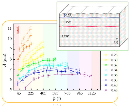
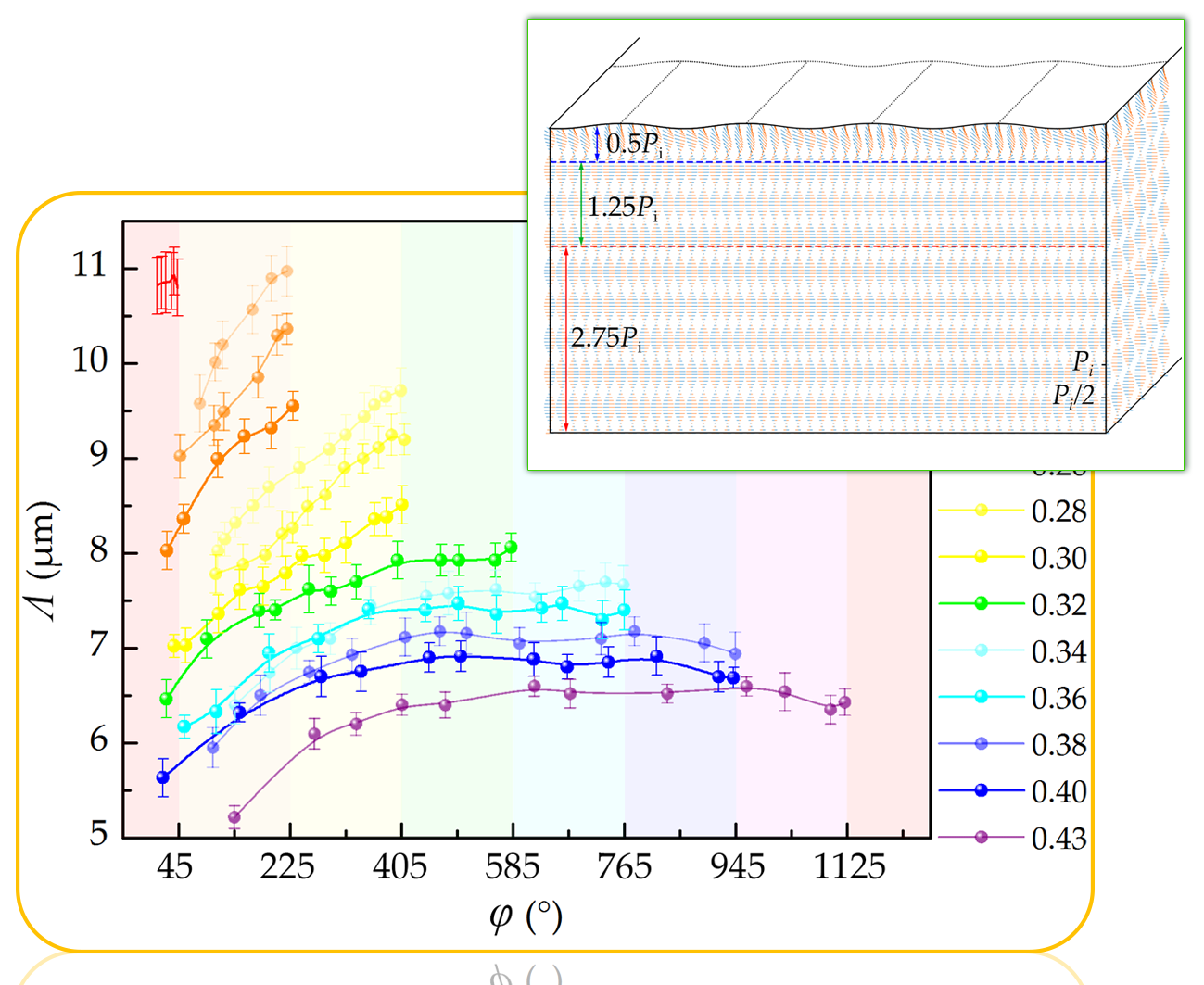
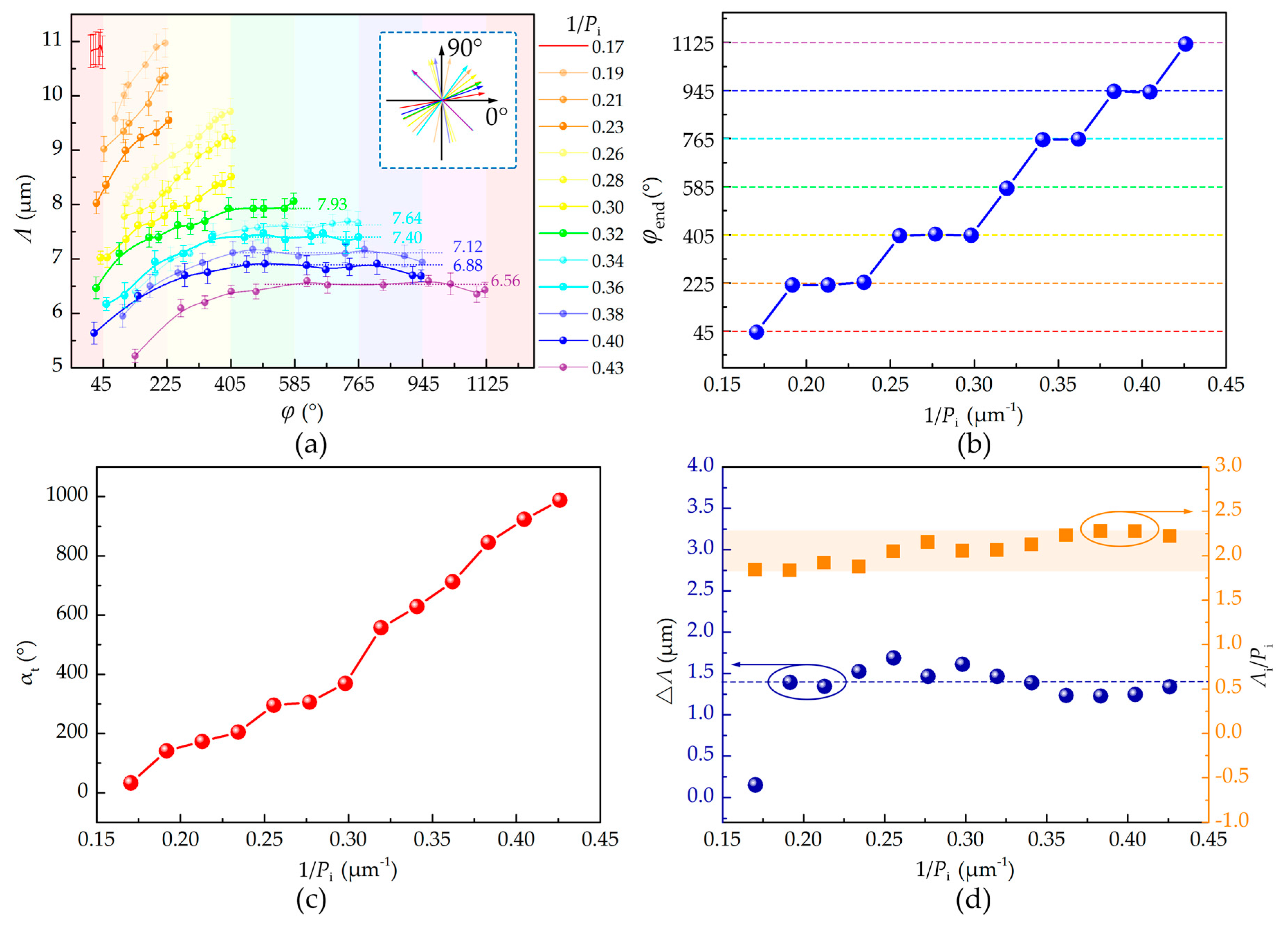
Figure 3a shows the dependencies of the grating pitch Λ and ϕ on the dopant concentration (labeled by 1/Pi). The initial orientation ϕi was measured once the CLC grating is formed, which is in the range of 0° to 180° as depicted in the inset of Figure 3a. The end orientation ϕend was determined when the grating was disappearing (Figure S2). The total continuous rotational angle is defined as αt = ϕend − ϕi. Other values of ϕ (Figure 3a) were selected during the exposure process. Because the contrast of CLC gratings with small 1/Pi is too low to determine the Λ, we present the experimental results from 1/Pi = 0.17 μm−1. On the basis of the above data, several rules can be concluded. First, as expected, larger 1/Pi induces smaller Λ. Second, ϕi is random, while ϕend = (1/4 + n)π (n = 0, 1, 2, …,6), which is clearly exhibited in Figure 3b. Third, αt is directly proportional to 1/Pi (Figure 3c). Fourth, when 0.17 μm−1 ≤ 1/Pi ≤ 0.30 μm−1, αt is smaller than 9π/4 and Λ monotonically increases with the exposure; when 0.32 μm−1 ≤ 1/Pi ≤ 0.43 μm−1, αt is larger than 9π/4 and Λ will reach and maintain at the maximum Λmax. The grating pitch is determined by the synergy of elastic force, chiral strength, and anchoring energy. We assume that the anchoring energy is constant. When 1/Pi is larger than 0.32, although P keeps increasing, the influences of ChAD-3c-S isomerization on the elastic force and the chiral strength become balanced. This results in the grating rotation and the maintenance of Λmax. Fifth, as revealed in Figure 3d, the ranges of the grating pitch tuning △Λ are all around 1.38 μm, except for △Λ = 0.15 at 1/Pi = 0.17 μm−1 (may be because of a very short time irradiation of blue light). Sixth, the value of Λi/Pi is in the range of 1.8 to 2.3 (Figure 3d), which is smaller than that of a hybrid alignment cell [12]. This phenomenon is attributed to the weaker anchoring at the LC/air interface compared to the homeotropic alignment layer.
3.2. Modelling of Director Configuration
Before constructing the model of the director configuration, we analyze some facts in our experiments. The thicknesses D of all the samples are constant as they are prepared in the same spin-coating process. Although Pi is different due to the varied chiral dopant concentrations, the helical pitch at the end state (Pend) should be the same. In this case, D is equal to aPend for all the semi-free films, where a is a constant describing the residual amount of the helical pitch. This assumption could be verified by the same ends of the cholesteric helixes (director at one end follows the preset alignment and at the other end is reflected by the end orientation of the CLC grating (Figure 3b and Figure S2). We divide the total semi-free film into two different parts. One is composed of planar helical layers, and the other is periodically distorted layers adjacent to the LC/air interface, due to the antagonistic anchoring condition. The CLC grating mainly arises from the phase retardation of the periodic change of LC tilt angle along the grating vector, and the periodic direction is determined by the orientation of a particular planar helical layer. Due to the continuous decrease of HTP under the blue light exposure, the cholesteric helixes will unwind gradually, accompanied by the rotation of the grating vector in the same direction.
We simulate the director configuration of the semi-free film based on Baudry’s model [12]. According to the model, periodic distorted helical layers corresponds to 0.5P. Here, the initial and end director configurations of the sample (1/Pi = 0.43 μm−1) are constructed (Figure 4). The semi-free film thickness is set as D = 4.5Pi_0.43 (Supplementary Material 1), and other required parameters are also determined according to the calculation (Supplementary Material 2). Figure 4a vividly reveals the director configuration of the sample at the initial state. There are four pitches in the planar helical layers. A zoomed-in image of the distorted helical layers (0.5 pitch) is presented as an inset. Figure 4b exhibits the director configuration of the same sample at the end state. Compared with director configuration in Figure 4a, 2.75 pitches are unwound, which is consistent with αt_0.43/360°. There are still 1.75 residual pitches left at the end state.
3.3. Two-Dimentional Precise Beam Steering
A 633 nm probe beam is normally incident to the sample of 1/Pi = 0.43 μm−1 to characterize the beam steering performance of the CLC grating. Circular polarization is adopted to avoid the influence of polarization-dependent effect on the diffraction efficiency. Figure 5a schematically shows the optical path for the characterization. The spiral line on the screen depicts the rotational trace of the 2nd diffraction order. At the beginning, the diffraction orders rotate and simultaneously move towards the central 0th order. Afterwards, they would rotate on several fixed concentric circumferences. Four typical photos are selected and exhibited in Figure 5b–e. The above phenomena agree with the results shown in Figure 3a. This facilitates a freely two-dimensional beam steering. Particularly, the rotation of diffraction orders with fixed radius is reported for the first time. It supplies a way for the precise control of beam propagation in a photoresponsive manner.
3.4. Synchronous Microparticle Rotation
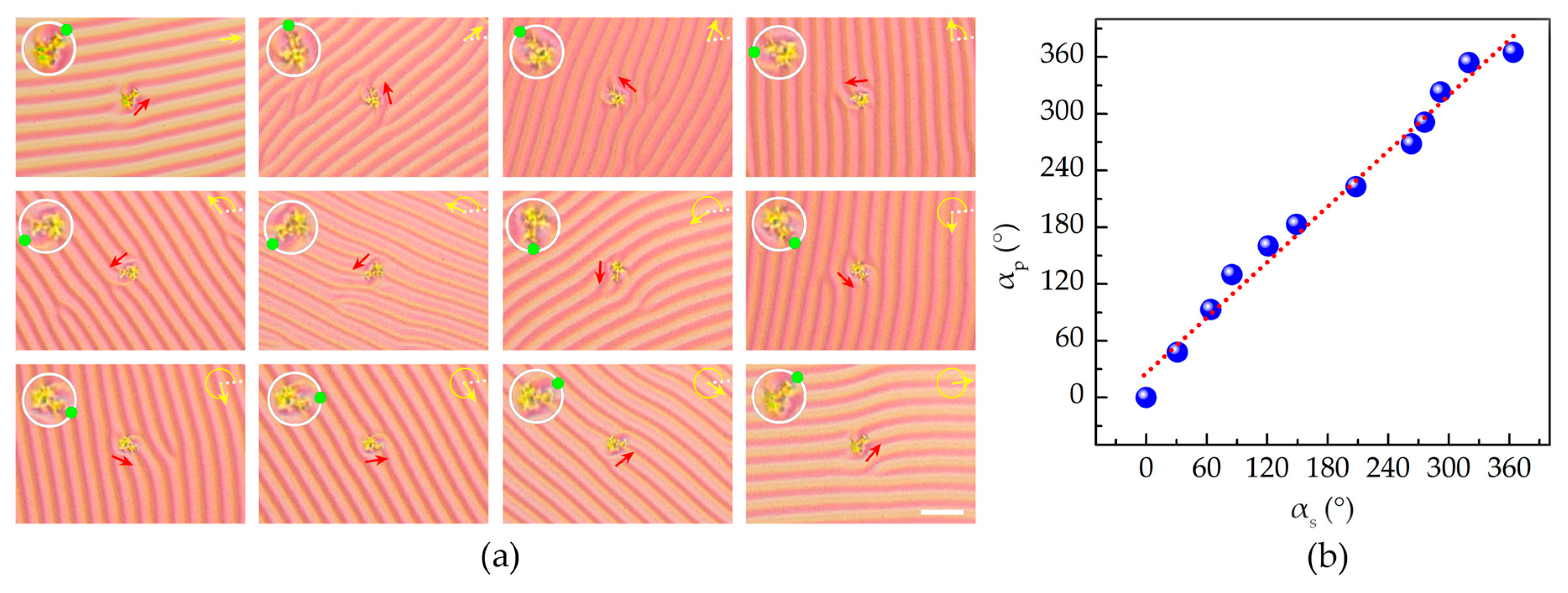
ZSM-5 zeolite microparticles are chosen for the demonstration of micromanipulation. The typical length of the long axis is ~12.6 µm and the aspect ratio is ~1.32. The microparticles of ZSM-5 zeolite are spattered onto the surface of the semi-free film, and then their rotation behaviors are monitored. Figure 6a shows the rotation of one of the microparticles. It rotates anticlockwise along with the rotation of the grating. The relationship between the rotational angle of microparticle and that of the CLC grating is depicted in Figure 6b. The fitted slope is ~0.98, suggesting that the particle could be precisely manipulated. Note that, after the grating disappears, the ZSM-5 zeolite can rotate with an extra angle of ~430°, which verifies that residual cholesteric helixes are still left at the end state. This finding opens a door for the precise micromanipulation by utilizing the cholesteric semi-free material system.
4. Conclusions
In summary, we investigate the light-driven rotation and pitch tuning of CLC gratings in semi-free films. Due to the continuous photoinduced modification of HTP, the CLC grating rotates along with the unwinding cholesteric helixes. This supplies great flexibility to the realization of continuous grating rotation. Dependencies of the light-driven rotation and pitch tuning on the dopant concentration and exposure are studied. The maximum rotational angle reaches 987.8°. The end grating orientations of all samples are fixed at the same direction. On the basis of the new understanding on the mechanism and rules of CLC gratings, the layer configuration of the semi-free film is simulated. The model depicts the director configuration of the sample and vividly reveals the relationship between the helixes unwinding and grating rotation. Distinct superiorities of the CLC gratings and applications including beam steering and micromanipulation are also demonstrated. Phenomena such as diffraction orders rotation on fixed concentric circumferences and synchronous rotation of microparticles with the CLC grating are reported for the first time. This work may offer new insights into the promising semi-free structured materials and inspire more fantastic applications.
Supplementary Materials
The following are available online at www.mdpi.com/2073-4360/9/7/295/s1, Figure S1: Schematic illustrations of the CLC grating in cells under the homogeneous, homeotropic and hybrid anchoring conditions. Figure S2: Polarized optical microscope textures of the end states of CLC gratings. Video S1: Reverse rotation processes of the CLC grating by switching the blue and green light. Supplementary Material 1: Determination of the semi-free film thickness. Supplementary Material 2: Modeling of director configuration of the CLC grating in a semi-free film.
Acknowledgments
The authors are indebted to Da-Yong Tian for the support of ZSM-5 zeolite microparticle, Peng Chen for constructive discussion and Shi-Jun Ge for assistance in video preparation. This work was sponsored by the National Key R&D Program of China under contract number 2017YFA0303700, the National Natural Science Foundation of China (Nos. 61490714, 61435008, 61535007 and 61575093) and the Fundamental Research Funds for the Central Universities.
Author Contributions
Wei Hu conceived the original idea; Ling-Ling Ma, Wei Duan, Ming-Jie Tang, Lu-Jian Chen and Xiao Liang performed the experiments, analyzed the data and wrote the manuscript; Wei Hu and Yan-Qing Lu co-supervised and directed the research.
Conflicts of Interest
The authors declare no conflict of interest.
References
- Jau, H.C.; Li, Y.; Li, C.C.; Chen, C.W.; Wang, C.T.; Bisoyi, H.K.; Lin, T.H.; Bunning, T.J.; Li, Q. Light-driven wide-range nonmechanical beam steering and spectrum scanning based on a self-organized liquid crystal grating enabled by a chiral molecular switch. Adv. Opt. Mater. 2015, 3, 166–170. [Google Scholar] [CrossRef]
- Kang, S.-W.; Sprunt, S.; Chien, L.-C. Polymer-stabilized cholesteric diffraction gratings: Effects of uv wavelength on polymer morphology and electrooptic properties. J. Am. Chem. Soc. 2006, 18, 1436–1441. [Google Scholar] [CrossRef]
- Kang, S.W.; Sprunt, S.; Chien, L.C. Structure and morphology of polymer-stabilized cholesteric diffraction gratings. Appl. Phys. Lett. 2000, 76, 3516. [Google Scholar] [CrossRef]
- Ma, L.-L.; Li, S.-S.; Li, W.-S.; Ji, W.; Luo, B.; Zheng, Z.-G.; Cai, Z.-P.; Chigrinov, V.; Lu, Y.-Q.; Hu, W.; Chen, L.-J. Rationally designed dynamic superstructures enabled by photoaligning cholesteric liquid crystals. Adv. Opt. Mater. 2015, 3, 1691–1696. [Google Scholar] [CrossRef]
- Li, W.-S.; Ma, L.-L.; Gong, L.-L.; Li, S.-S.; Yang, C.; Luo, B.; Hu, W.; Chen, L.-J. Interlaced cholesteric liquid crystal fingerprint textures via sequential uv-induced polymer-stabilization. Opt. Mater. Express 2016, 6, 19–28. [Google Scholar] [CrossRef]
- Hung, W.-C.; Cheng, W.-H.; Liu, T.-K.; Jiang, I.M.; Tsai, M.-S.; Yeh, P. Diffraction of cholesteric liquid crystal gratings probed by monochromatic light from 450 to 750 nm. J. Appl. Phys. 2008, 104, 073106. [Google Scholar] [CrossRef]
- Yao, I.A.; Liaw, C.-H.; Chen, S.-H.; Wu, J.-J. Direction-tunable cholesteric phase gratings. J. Appl. Phys. 2004, 96, 1760–1762. [Google Scholar] [CrossRef]
- Igor Gvozdovskyy, O.Y.; Serbina, M.; Yamaguchi, R. Photoinduced helical inversion in cholesteric liquid crystal cells with homeotropic anchoring. Opt. Express 2012, 20, 3499–3508. [Google Scholar] [CrossRef] [PubMed]
- Oswald, P.; Baudry, J.; Pirkl, S. Static and dynamic properties of cholesteric fingers in electric field. Phys. Rep. 2000, 337, 67–96. [Google Scholar] [CrossRef]
- Khoo, I.C.; Xiang, J.; Shiyanovskii, S.V.; Li, Y.; Imrie, C.T.; Li, Q.; Lavrentovich, O.D. Electrooptics of chiral nematics formed by molecular dimers. Proc. SPIE Liq. Cryst. XVIII 2014, 91820P. [Google Scholar] [CrossRef]
- Ryabchun, A.; Bobrovsky, A.; Stumpe, J.; Shibaev, V. Rotatable diffraction gratings based on cholesteric liquid crystals with phototunable helix pitch. Adv. Opt. Mater. 2015, 3, 1273–1279. [Google Scholar] [CrossRef]
- Baudry, J.; Brazovskaia, M.; Lejcek, L.; Oswald, P.; Pirkl, S. Arch-texture in cholesteric liquid crystals. Liq. Cryst. 1996, 21, 893–901. [Google Scholar] [CrossRef]
- Lin, C.-H.; Chiang, R.-H.; Liu, S.-H.; Kuo, C.-T.; Huang, C.-Y. Rotatable diffractive gratings based on hybrid-aligned cholesteric liquid crystals. Opt. Express 2012, 20, 26837–26844. [Google Scholar] [CrossRef] [PubMed]
- Hung, W.-C.; Cheng, W.-H.; Tsai, M.-S.; Juan, Y.-C.; Jiang, I.M.; Yeh, P. Surface plasmon enhanced diffraction in cholesteric liquid crystals. Appl. Phys. Lett. 2007, 90, 183115. [Google Scholar] [CrossRef]
- Nose, T.; Miyanishi, T.; Aizawa, Y.; Ito, R.; Honma, M. Rotational behavior of stripe domains appearing in hybrid aligned chiral nematic liquid crystal cells. Jpn. J. Appl. Phys. 2010, 49, 051701. [Google Scholar] [CrossRef]
- Zheng, Z.-G.; Li, Y.; Bisoyi, H.K.; Wang, L.; Bunning, T.J.; Li, Q. Three-dimensional control of the helical axis of a chiral nematic liquid crystal by light. Nature 2016, 531, 352–356. [Google Scholar] [CrossRef] [PubMed]
- Wang, Y.; Li, Q. Light-driven chiral molecular switches or motors in liquid crystals. Adv. Mater. 2012, 24, 1926–1945. [Google Scholar] [CrossRef] [PubMed]
- Xiang, J.; Shiyanovskii, S.V.; Imrie, C.; Lavrentovich, O.D. Electrooptic response of chiral nematic liquid crystals with oblique helicoidal director. Phys. Rev. Lett. 2014, 112, 217801. [Google Scholar] [CrossRef]
- Ryabchun, A.; Bobrovsky, A.; Stumpe, J.; Shibaev, V. Electroinduced diffraction gratings in cholesteric polymer with phototunable helix pitch. Adv. Opt. Mater. 2015, 3, 1462–1469. [Google Scholar] [CrossRef]
- Khoo, I.-C.; Senyuk, B.; Smalyukh, I.; Lavrentovich, O. Electrically-controlled two-dimensional gratings based on layers undulations in cholesteric liquid crystals. Proc. SPIE Liq. Cryst. IX 2005, 59360W. [Google Scholar] [CrossRef]
- Zhang, L.; Wang, L.; Hiremath, U.S.; Bisoyi, H.K.; Nair, G.G.; Yelamaggad, C.V.; Urbas, A.M.; Bunning, T.J.; Li, Q. Dynamic orthogonal switching of a thermoresponsive self-organized helical superstructure. Adv. Mater. 2017, 29, 1700676. [Google Scholar] [CrossRef] [PubMed]
- Jeong, H.S.; Kim, Y.H.; Lee, J.S.; Kim, J.H.; Srinivasarao, M.; Jung, H.T. Chiral nematic fluids as masks for lithography. Adv. Mater. 2012, 24, 381–384. [Google Scholar] [CrossRef] [PubMed]
- Kim, Y.; Tamaoki, N. A photoresponsive planar chiral azobenzene dopant with high helical twisting power. J. Mater. Chem. C 2014, 2, 9258–9264. [Google Scholar] [CrossRef]
- Eelkema, R.; Pollard, M.M.; Vicario, J.; Katsonis, N.; Ramon, B.S.; Bastiaansen, C.W.; Broer, D.J.; Feringa, B.L. Molecular machines: Nanomotor rotates microscale objects. Nature 2006, 440, 163. [Google Scholar] [CrossRef] [PubMed]
- Ayeb, H.; Grand, J.; Sellame, H.; Truong, S.; Aubard, J.; Felidj, N.; Mlayah, A.; Lacaze, E. Gold nanoparticles in a cholesteric liquid crystal matrix: Self-organization and localized surface plasmon properties. J. Mater. Chem. 2012, 22, 7856–7862. [Google Scholar] [CrossRef]
- Eelkema, R.; Pollard, M.M.; Katsonis, N.; Vicario, J.; Broer, D.J.; Feringa, B.L. Rotational reorganization of doped cholesteric liquid crystalline films. J. Am. Chem. Soc. 2006, 128, 14397–14407. [Google Scholar] [CrossRef] [PubMed]
- Mitov, M.; Portet, C.; Bourgerette, C.; Snoeck, E.; Verelst, M. Long-range structuring of nanoparticles by mimicry of a cholesteric liquid crystal. Nat. Mater. 2002, 1, 229–231. [Google Scholar] [CrossRef] [PubMed]
- Thomas, R.; Yoshida, Y.; Akasaka, T.; Tamaoki, N. Influence of a change in helical twisting power of photoresponsive chiral dopants on rotational manipulation of micro-objects on the surface of chiral nematic liquid crystalline films. Chem. Eur. J. 2012, 18, 12337–12348. [Google Scholar] [CrossRef] [PubMed]
- Bosco, A.; Jongejan, M.G.; Eelkema, R.; Katsonis, N.; Lacaze, E.; Ferrarini, A.; Feringa, B.L. Photoinduced reorganization of motor-doped chiral liquid crystals: Bridging molecular isomerization and texture rotation. J. Am. Chem. Soc. 2008, 130, 14615–14624. [Google Scholar] [CrossRef] [PubMed]
- Chigrinov, V.G.; Kozenkov, V.M.; Kwok, H.S. Photoalignment of Liquid Crystalline Materials: Physics and Applications; John Wiley & Sons: West Sussex, UK, 2008; pp. 69–100. [Google Scholar]
- Hu, W.; Kumar Srivastava, A.; Lin, X.W.; Liang, X.; Wu, Z.J.; Sun, J.T.; Zhu, G.; Chigrinov, V.G.; Lu, Y.Q. Polarization independent liquid crystal gratings based on orthogonal photoalignments. Appl. Phys. Lett. 2012, 100, 111116. [Google Scholar] [CrossRef]
- Srivastava, A.K.; Hu, W.; Chigrinov, V.G.; Kiselev, A.D.; Lu, Y.Q. Fast switchable grating based on orthogonal photo alignments of ferroelectric liquid crystals. Appl. Phys. Lett. 2012, 101, 031112. [Google Scholar] [CrossRef]
- Wu, H.; Hu, W.; Hu, H.C.; Lin, X.W.; Zhu, G.; Choi, J.W.; Chigrinov, V.G.; Lu, Y.Q. Arbitrary photo-patterning in liquid crystal alignments using dmd based lithography system. Opt. Express 2012, 20, 16684–16689. [Google Scholar] [CrossRef]
- Hsiao, Y.-C.; Huang, K.-C.; Lee, W. Photo-switchable chiral liquid crystal with optical tristability enabled by a photoresponsive azo-chiral dopant. Opt. Express 2017, 25, 2687–2693. [Google Scholar] [CrossRef]
- Huang, K.C.; Hsiao, Y.C.; Timofeev, I.V.; Zyryanov, V.Y.; Lee, W. Photo-manipulated photonic bandgap devices based on optically tristable chiral-tilted homeotropic nematic liquid crystal. Opt. Express 2016, 24, 25019–25025. [Google Scholar] [CrossRef] [PubMed]
- Chen, C.-W.; Li, C.-C.; Jau, H.-C.; Lee, C.-H.; Wang, C.-T.; Lin, T.-H. Bistable light-driven π phase switching using a twisted nematic liquid crystal film. Opt. Express 2014, 22, 12133–12138. [Google Scholar] [CrossRef] [PubMed]
- De Gennes, P.G.; Prost, J. The Physics of Liquid Crystals; Clarendon: Oxford, UK, 1993. [Google Scholar]
- Kausar, A.; Nagano, H.; Ogata, T.; Nonaka, T.; Kurihara, S. Photocontrolled translational motion of a microscale solid object on azobenzene-doped liquid-crystalline films. Angew. Chem. Int. Ed. 2009, 48, 2144–2147. [Google Scholar] [CrossRef] [PubMed]
Figure 1.
Schematics of (a) the cholesteric liquid crystal (CLC) helical structure and (b) the helical layers with a self-adapted distortion in a semi-free film. The distance between two adjacent layers equals to half a pitch. The orange layer represents the planar alignment film.
Figure 1.
Schematics of (a) the cholesteric liquid crystal (CLC) helical structure and (b) the helical layers with a self-adapted distortion in a semi-free film. The distance between two adjacent layers equals to half a pitch. The orange layer represents the planar alignment film.
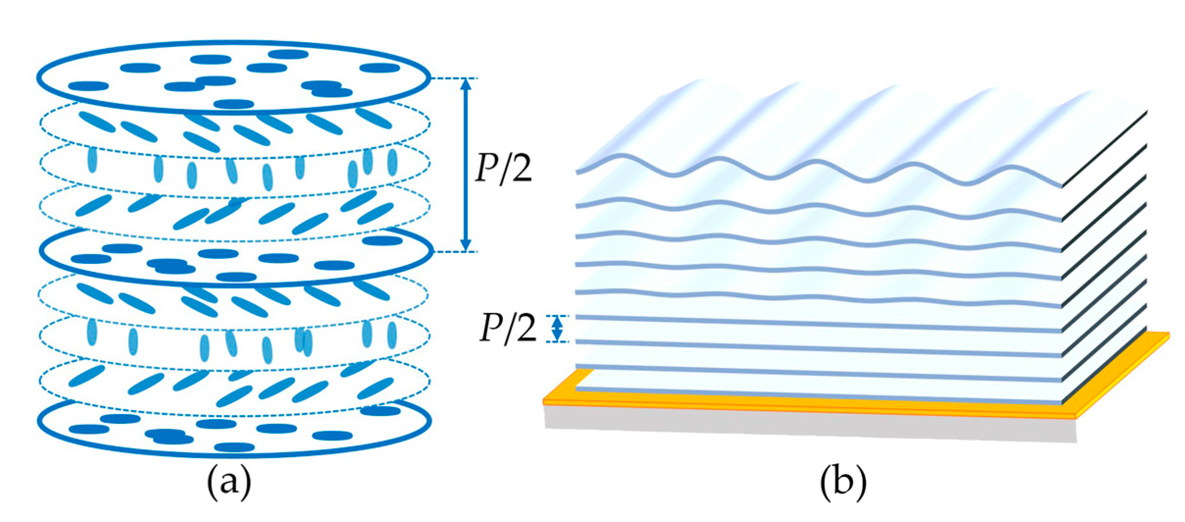
Figure 2.
Light-driven rotation of the CLC grating (1 wt % ChAD-3c-S) along with the increasing exposure. The rotational angle is labeled in each top-left corner. The scale bar represents 25 μm for all images.
Figure 2.
Light-driven rotation of the CLC grating (1 wt % ChAD-3c-S) along with the increasing exposure. The rotational angle is labeled in each top-left corner. The scale bar represents 25 μm for all images.
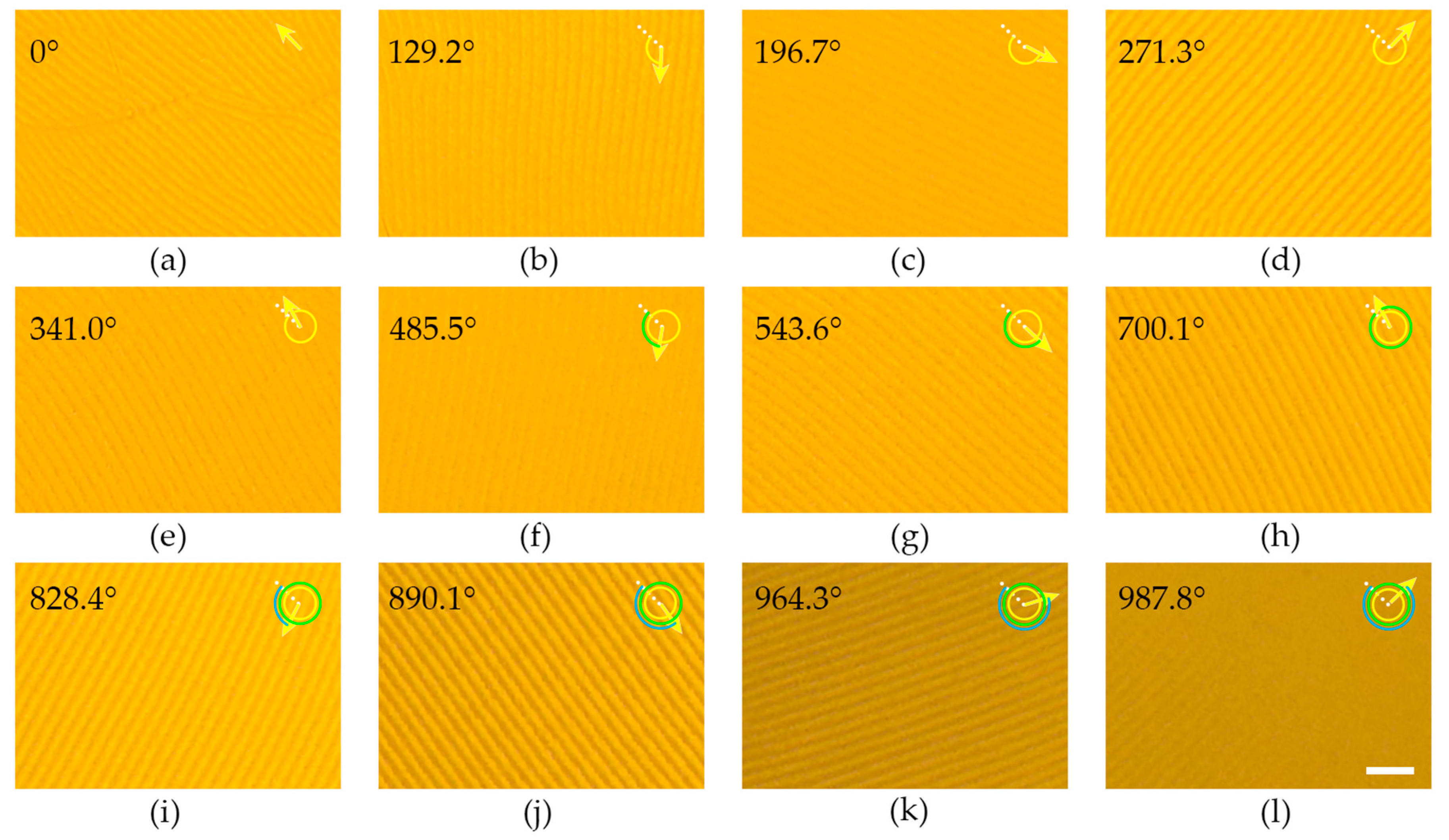
Figure 3.
Dependencies of (a) Λ and ϕ on 1/Pi, (b) on 1/Pi, (c) αt on 1/Pi, and (d) △Λ and Λi/Pi on 1/Pi.
Figure 3.
Dependencies of (a) Λ and ϕ on 1/Pi, (b) on 1/Pi, (c) αt on 1/Pi, and (d) △Λ and Λi/Pi on 1/Pi.

Figure 4.
Simulated director configurations of the CLC grating (1 wt % ChAD-3c-S) at the (a) initial state and (b) end state. The inset in (a) shows a zoomed-in image. The anchoring directions are represented by orange arrows.
Figure 4.
Simulated director configurations of the CLC grating (1 wt % ChAD-3c-S) at the (a) initial state and (b) end state. The inset in (a) shows a zoomed-in image. The anchoring directions are represented by orange arrows.
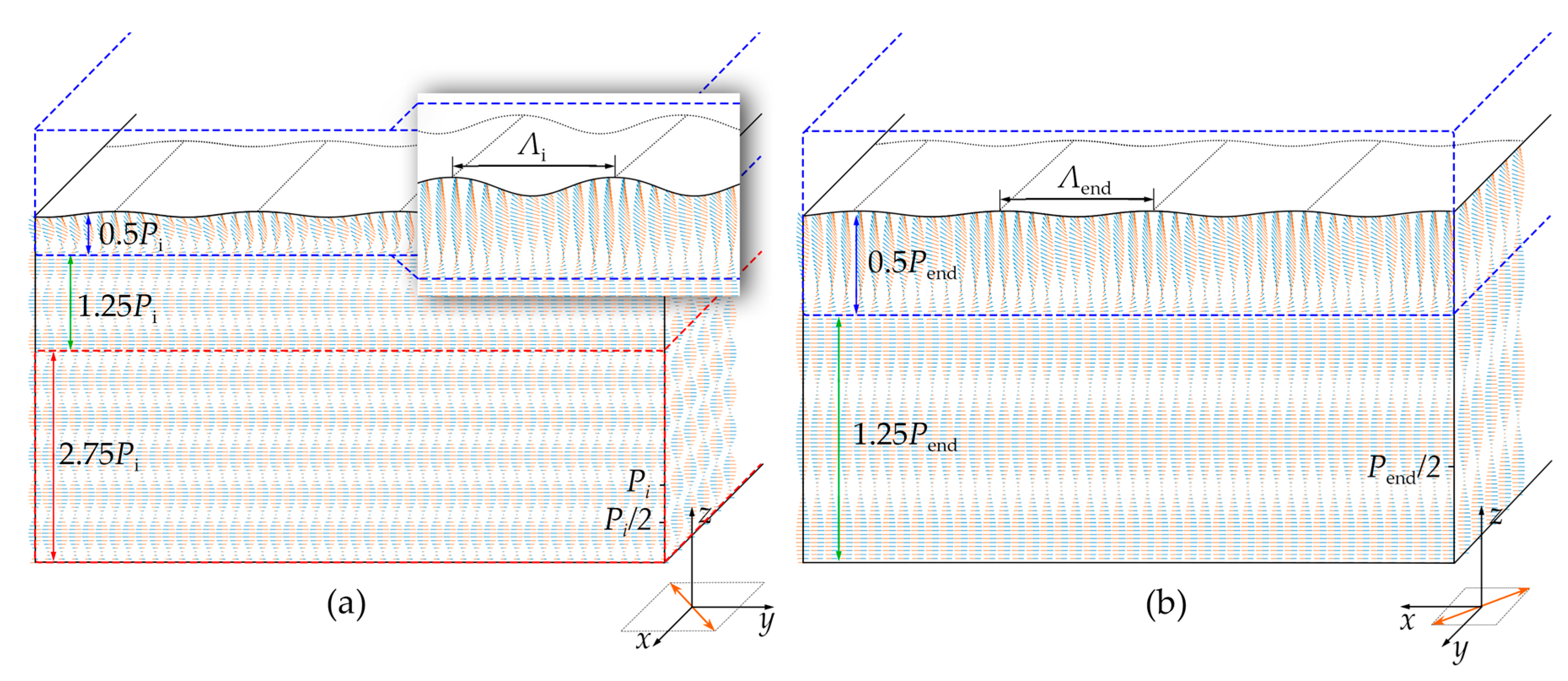
Figure 5.
(a) Schematic diagram of the optical path for the beam steering characterization. (b–e) Diffraction patterns collected in the directions of 0°, 45°, 90°, and 135°, respectively.
Figure 5.
(a) Schematic diagram of the optical path for the beam steering characterization. (b–e) Diffraction patterns collected in the directions of 0°, 45°, 90°, and 135°, respectively.
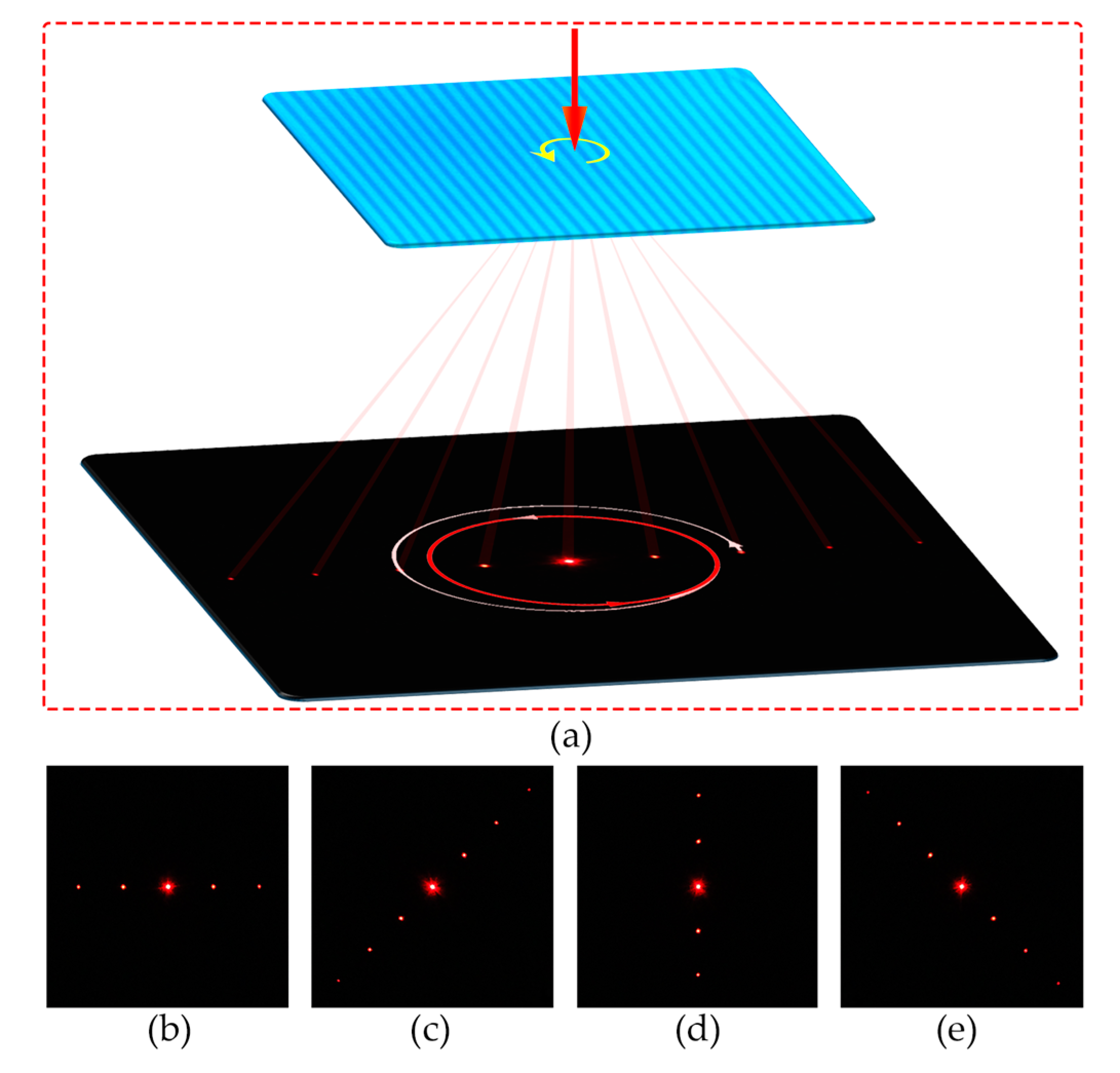
Figure 6.
(a) Polarized optical microscope textures of the ZSM-5 zeolite microparticle rotation on the semi-free film. The enlarged microparticle is presented in the top left corner with a green dot denoting its orientation. The scale bar represents 25 µm for all images. (b) Relationship between the rotational angle of the microparticle and that of the CLC grating. The dashed line is the linear fitting result.
© 2017 by the authors. Licensee MDPI, Basel, Switzerland. This article is an open access article distributed under the terms and conditions of the Creative Commons Attribution (CC BY) license (http://creativecommons.org/licenses/by/4.0/).
Share and Cite
MDPI and ACS Style
Ma, L.-L.; Duan, W.; Tang, M.-J.; Chen, L.-J.; Liang, X.; Lu, Y.-Q.; Hu, W. Light-Driven Rotation and Pitch Tuning of Self-Organized Cholesteric Gratings Formed in a Semi-Free Film. Polymers 2017, 9, 295. https://doi.org/10.3390/polym9070295
AMA Style
Ma L-L, Duan W, Tang M-J, Chen L-J, Liang X, Lu Y-Q, Hu W. Light-Driven Rotation and Pitch Tuning of Self-Organized Cholesteric Gratings Formed in a Semi-Free Film. Polymers. 2017; 9(7):295. https://doi.org/10.3390/polym9070295
Chicago/Turabian StyleMa, Ling-Ling, Wei Duan, Ming-Jie Tang, Lu-Jian Chen, Xiao Liang, Yan-Qing Lu, and Wei Hu. 2017. "Light-Driven Rotation and Pitch Tuning of Self-Organized Cholesteric Gratings Formed in a Semi-Free Film" Polymers 9, no. 7: 295. https://doi.org/10.3390/polym9070295
Note that from the first issue of 2016, this journal uses article numbers instead of page numbers. See further details here.